Drayton Digistat +CRF 13616 Cylinder Thermostat

Installation For SCR

If you do not have the knowledge to install the SCR safely then you must arrange for a competent electrician to install it for you. Wiring must conform to the current IEE wiring regulations.
Prior to commencing the installation you must ensure the mains supply is switched off.
Installation Instructions
Read all installation and commissioning instructions before proceeding. Do not switch on until ready to commission.
The system wiring must be able to be fully disconnected from the mains supply by a switch incorporated in the fixed wiring having a contact separation of at least 3mm on both poles. Fused at 3A.
Location
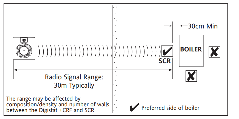
The Digistat+C SCR (receiver) should be mounted in a convenient position, close to the boiler or central heating system wiring centre. (Care should be taken not to mount the SCR in a position where it is surrounded by metal objects or mains voltage cable, as this may interfere with the radio signal).
For the best performance install in an open space, at least 30cm
distance from any metal objects including wall boxes and boiler housing. It is recommended that the SCR is mounted on the wall nearest the fina I location of the Digistat+C RF thermostat and not less than 30cm from the boiler side panel.
Warning: Installing the SCR too close to the metal side panel or main cables may interfere with the radio signal.
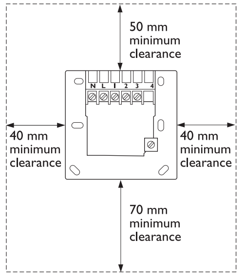
Fixing (minimum wall plate clearances shown)
- Loosen the securing screws, remove the wallplate, and if surface wiring is to be used, snap out the cable entry strip on the bottom edge of the wallplate with a pair of pliers.
- Fix the wallplate, and terminals at the top, either direct onto the flat wall using wall plugs and no 6 x1″ wood screws or on a flush mounting single conduit box using M3.5x 14 screws. Minimum wallplate clearances are shown.
- Complete the wiring to the SCR wallplate in accordance with the relevant diagram, to comply with current IEE wiring regulations.
- Place the SCR onto the wallplate and tighten the securing screws.
SCR wallplate clearances
 Electrical
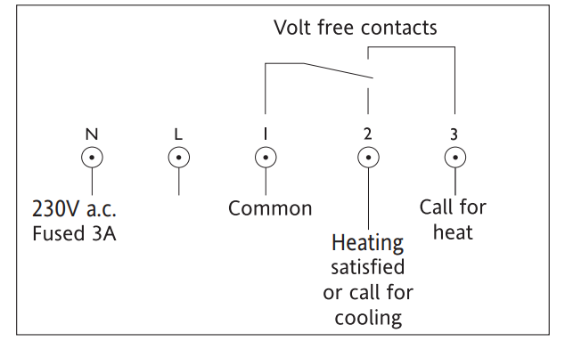
This product is double insulated and does not require an earth connection. The SCR should be wired to the combi boiler or central heating wiring using the correct type of cable or flex. The SCR should be wired in to replace hard wired room or programmable thermostats shown on the system or boiler wiring diagrams. Always check other manufacturers’ instructions for compatibility.
DHW Cylinder Thermostat

COMMISSIONING THE WIRELESS SYSTEM
The standard for all models
IMPORTANT: MULTIZONE INSTALLATIONS ONLY If more than one ‘wireless system’ is fitted within the same property. e. for controlling 2 or more zones (multi-zone) it Is essential that the Digistat RF units are matched correctly to the relevant SCR. This is easily achieved by commissioning each Digistat and SCR in turn.
- Install (see installation instructions) and turn the power on to the SCR (receiver). If a separate programmer is fitted, ensure that it is switched on. The red LED should come on.
- Push the ‘Boost 1 Hr’button on the SCR once. The green LED should also come on. Check to see if the boiler and/or motorized valve are working
- To enter learn’ mode push the button marked 1 followed by 2 (Boost 1 Hr) and hold both depressed together. The red LEDP should flash for 2 seconds and then go out signifying the SCR is in learn mode. Release both buttons.
- The red and green LEDs should both now be on.
- Take the Digistat+C RF and hold it within sight of the SCR (no closer than one meter).
- Insert the batteries into the holder and slide them into the Digistat+CRF until the drawer clicks into place.
- The Digistat+C RF should now display the ‘EZ’ and the RF symbol ?’.f the unit has been stored in a cold place, it may take time to warm up.
- As soon as the battery compartment is slid back into place, the red LED on the SCR should flash for 7 seconds and then go out.
- If the red LED remains on, slide down the battery drawer on the Digistat+C RF, check the battery positions are correct, and once the display has faded, repeat steps 6 to 8.
- Increase the ‘SET temperature on the Digistat+C RF by rotating the dial clockwise until a flame symbol appears, in the left-hand segment of the display.
- The red LED on the SCR should flash for 7 seconds. This confirms that the radio signal is being sent and received. After 7 seconds the red LED should go out and the green one come on.
- 12. Check to confirm that the boiler and/or motorized valves are Working.
- Decrease the ‘SET temperature on the Digistat+C RF by rotating the dial anticlockwise until the flame symbol disappears.
- The red LED on the SCR should flash for 7 seconds. After 7 rounds both the red and green LEDs should go out. Check that the boiler and/or motorized valve have powered down.
- Place the Digistat+C RF in the chosen operating position, (see Digistat+C RF location section) and repeat steps 10 to 14. Once you have confirmed the system operates correctly, the Digistat+C RF transmitter unit and sensor can be installed. When the sensor is wired to the transmitter unit, the display will change after approx. 30 seconds to show the current setpoint and E2′ will disappear (see installation instructions).
During normal operation, the red LED on the SCR will flash for 7 seconds each time a radio signal is received from the Digistat RF. This will occur approximately every 5 minutes. The green LED on the SCR denotes a call for heat (ON). Once the system has been successfully commissioned, buttons 1 and 2 on the SCR should not be pressed simultaneously, unless a replacement Digistat RF or SCR is fitted.
COMMISSIONING THE CYLINDER THERMOSTAT
To assist with commissioning or checking the system operation, there is a positive OFF setting outside the temperature scale on the cylinder thermostat. First adjust the minimum temperature setting to 40C as described in the user guide, then rotate the dial fully anticlockwise for OFF.
REFERENCE
Download Manual
Drayton Digistat +CRF 13616 Cylinder Thermostat Installation Guide
Other manuals:
Drayton Digistat +CRF 13616 Cylinder Thermostat USER Guide
Drayton Digistat +CRF 13616 Cylinder Thermostat Product Specifications Guide

Drayton Digistat +CRF 13616 Cylinder Thermostat Installation Guide