Peco TB180 Programmable Thermostat
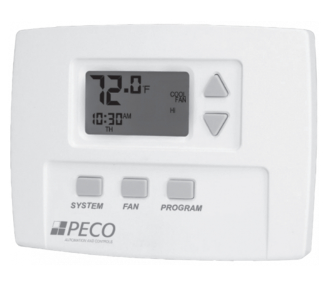
APPLICATIONS AND FEATURES
For 2 or 4 Pipe Fan Coil and On/Off Control Applications
- 7 Day, 4 Event Programmability
- System Selection: Off-Heat-Cool-Auto-Setback
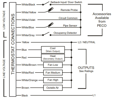
- 6 Outputs: 1H, 1C, Up to 3 Fan, OA Damper
- Fan Control: 1-3 Speeds
Cycling (Auto) or Continuous (On)
Automatic Fan Speed Staging (TB180 models only)
Connections for:
- Fan Coil Pipe Sensor
- Remote Temperature Probe
- Occupancy Control
- Door Switch or Setback
- Condensate Overflow
WARNING
- READ THESE INSTRUCTIONS CAREFULLY BEFORE ATTEMPTING TO INSTALL, OPERATE OR SERVICE THIS THERMOSTAT.
- Failure to observe safety information and comply with instructions could result in PERSONAL INJURY, DEATH AND/OR PROPERTY DAMAGE.
- To avoid electrical shock or damage to equipment, disconnect power before installing or servicing and use only wiring with insulation rated for full thermostat operating voltage.
- Before installing this control, the Voltage Selection Switch must be placed in the correct position. See instructions.
- To avoid potential fire and/or explosion do not use in potentially flammable or explosive atmospheres.
- Retain these instructions for future reference. This product, when installed, will be part of an engineered system whose specifications and performance characteristics are not designed or controlled by PECO. You must review your application and national and local codes to assure that your installation will be functional and safe.
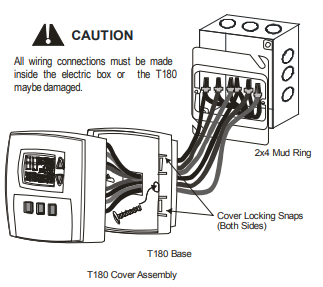
CAUTION
- Use copper wire only, insulate or wire nut all unused leads.
- Care should be used to avoid electrostatic discharge to the T180 thermostat.
- This unit has configuration jumpers. You may need to reconfigure this thermostat for your application.
SPECIFICATIONS
- Temperature Set Point Range: 50 to 90°F / 10 to 32°C
- Differential : 1°
- Memory – Back-Up: EEPROM, No batteries required, Stores settings for unlimited time
- Mounting: Installs on standard 4” x 4” device box with a 2” x 4” horizontal mud ring
- Physical Dimensions: 4.4”H x 5.8”W x 1.1”D
- Agency Approvals: UL, UL Canada
- Electrical Ratings: (see Ratings table)
| RATINGS | |||||
| VOLTAGE | RES AMPS | PILOT DUTY | HP | ||
| FLA | LRA | ||||
| 24 VAC | NA | NA | NA | 24 VA | NA |
| 120 VAC | 5.8 | 34.8 | 6.0 | 125 VA | 1/4 |
| 240 VAC | 2.9 | 17.4 | 5.0 | 125 VA | 1/4 |
| 277 VAC | 2.4 | 14.4 | 4.2 | 125 VA | 1/4 |
| COMBINED LOAD CURRENT NOT TO EXCEED 20 AMPS | |||||
INSTALLATION
New Installations
The thermostat should be used indoors only. It should be mounted on an inner wall in a location with freely circulating air, and where it will be responsive to changes in room temperature. Avoid mounting near heat generating appliances (i.e. TV, heater, refrigerator), or in direct sunlight.
Remove Old Thermostat
- Turn off power to thermostat at main fuse or circuit breaker box. Ensure that ALL power is disconnected. To prevent electrical shock and /or equipment damage, disconnect electrical power to the system at the main fuse or circuit breaker until installation is complete.
- Remove the front cover of old thermostat. With wires still attached, remove wall plate from the wall. If the old thermostat has a wall mounting plate, remove the thermostat and the wall mounting plate as an assembly.
- Before removing wires from old thermostat, label each wire with the terminal designation from which it was attached.
- Disconnect the wires from the old thermostat one at a time. Do not let wires fall back into the wall.
Jumper and Circuit Board Selections
Voltage Selection Switch: This switch must be placed in the appropriate position prior to application of power.
- 24V = 24 VAC
- 110-277 V = 120, 240 or 277 VAC

JP1 Jumper Selection – Remote Temperature Sensor:
- Local Sensing – Install JP1
- Remote Sensing – Remove JP1 – Accessory sensors are available in standard 60” lengths but can be extended to meet application requirements.
JP3 Jumper Selection – HVAC Setback Systems:
The JP3 jumper allows the T180 to be configured for Setback, Occupancy Detection or Door Switch Only Occupancy Operations. For further descriptions of these conditions please see the Technical/Application Section.
- Setback Operation – Remove JP3
- Occupancy Detection – Install JP3
- Door Switch Only – Install JP3
JP4 Jumper Selection – 2 or 4 Pipe Operation: Connection of a pipe sensor will change the operation of the outputs as shown in the table below. (See Technical Notes for further information on Pipe Sensor Operation)
- 2-Pipe Operation – Install JP4 – The thermostat will permanently disable the Secondary Output and disables system and fan invalid modes.
- 4-Pipe Operation – Remove JP4 – Both the Main Output (COOL) and Secondary Output (HEAT) will be available.
|
JP4 Selection |
Pipe Sensor Water
Temp |
Aqua Stat |
Main Output (Blue Wire) |
Secondary Output (Red Wire) |
| 2-Pipe
JP4-ON |
COLD | Open | Cooling ONLY | Disabled |
| HOT | Closed | Heating ONLY | Disabled | |
| 4-Pipe JP4-OFF | COLD | Open | Cooling | Heating |
| HOT | Closed | Heating ONLY | Disabled | |
| * Fan will not cycle on for disabled modes. | ||||
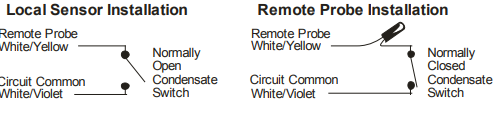
Condensate Overflow Interrupt
The remote probe input can be used with a condensate overflow interrupt switch (CO), either in conjunction with a remote probe (normally closed CO switch) or with local sensing (normally open CO switch). When the condensate switch activates, the T180 will display the service wrench and disable all outputs
Mounting Thermostat
- Thermostat mounts to a 4” x 4” box with a 2” x 4” mud ring. Adapter wall plates are available if needed.
- Pull wires through the hole of the thermostat base.
- Mount thermostat base to the wall using the enclosed mounting screws. Tighten screws evenly but do not over tighten.
- Verify that the circuit board is firmly snapped into the cover and has not been dislodged during handling.
- Match and connect equipment wire thermostat using the appropriate wiring schematic as shown at the bottom of the page on the left-hand side.
- Wire nut all unused wires or terminate properly according to local building codes.
- Mount the base to the mud ring and install the cover assembly. Firmly press cover to engage the cover locking snaps. Should the cover need to be removed in the future, use a flat edged tool to put pressure on the base sides. This will release the four side latches.
- Turn on power to equipment.
System Check-out
- After wiring and installation is complete, energize the system.
- Set fan to ON. Select each fan speed (TA180 Models) to verify operation.
- Set the System button to AUTO, or available selection.
- Using the UP arrow, adjust temperature more than 5°F above the room temperature to cycle on heating.
- Using the DOWN arrow adjust the temperature to 5°F below room temperature to cycle on cooling.
Note: If the thermostat is set to utilize a time-based purge cycle (Service menu 16), the thermostat will conduct a 3-min purge on initial start-up if a pipe sensor is connected.
THERMOSTAT CONFIGURATION / SERVICE MENU
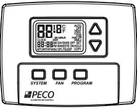
To enter the Service Menu press the UP and DOWN arrows simultaneously for five (5) seconds. The current display icon will be turned off.
Service menu number 1 will appear. Push the SYSTEM button to move to the next Service Menu number. The UP and DOWN arrow keys will scroll through your range of options for each feature. All changes to the Service Menu are automatically saved when the system times out. Please refer to the service menu table on page three.
USER OPERATION
Please refer to T180 Programmable Thermostat Owner’s Manual for operating instructions
TECHNICAL / APPLICATION NOTES
Standard Fan Operation: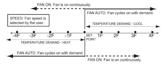
| Menu | feature | ranGe | description / coMMents |
| 1 | F° or C° | 0- Celsius
1- Fahrenheit (Default) |
Determines temperature displays in Fahrenheit or Celsius |
| 3 | Fan Off Delay | 0-99 Seconds (0- Default) | The amount of time (in seconds) the lowest available fan speed will run after the thermostat outputs are disabled. |
| 4 | Range Low | 50-90°F, 10-32°C (50°F- Default) | The lowest selectable temperature setpoint value. |
| 5 | Range High | 50-90°F, 10-32°C (90°F- Default) | The highest selectable temperature setpoint value. |
| 6 | Setback Low | 0- OFF
50-82°F, 11-27°C (55°F- Default) |
The temperature setpoint value you want the thermostat to Heat to when the T180 is in the Setback mode. |
| 7 | Setback High | 0- OFF
50-90°F, 11-32°C (90°F- Default) |
The temperature setpoint value you want the thermostat to Cool to when the T180 is in the Setback mode. |
| 8 | Zone Temp Offset | +/- 9°F or +/- 4.5°C (0°F- Default) | Zone Temperature offset adjusts the sensed Zone Temperature displayed, allowing calibration in the field. |
| 9 | Keypad Lockout | 0- No keypad lockout (Default)
1- Disables System/Fan/Program 2- Disables all buttons |
This function blocks access to certain features of the device. The Service Menu is still available if the keypad lockout is enabled. |
| 10 | Fan Mode | 1- ON
2- Auto 3- ON or Auto (Default) |
ON- Fan is always on, regardless of demand.
Auto- Fan is only on with heating or cooling demand. ON or Auto- User can choose either selection. |
| 11 | Fan Speeds | 1- High
2- Low, High 3- Low, Med, High (Default) |
Speeds which are selectable by the user. |
| 12 | System Mode | OFF, Auto
OFF, Heat, Cool, Auto (Default) OFF, Heat, Cool Heat, Cool, Auto |
Sets the system modes the occupant is able to select. |
| 13 | Controlled Off or Off Override | 0- Disable (Default)
1- Enable |
When enabled, the unit will control to the Setback setpoints. This function will also override the user mode setting of OFF if the room temperature is equal to or above the Cool Setback setpoint or equal to or below the Heat Setback setpoint. |
| 14 | Front Panel Setback Control | 0- Disable (Default)
1- Enable |
When enabled, Setback is shown as an available system mode selection. If Setback mode is selected, the
thermostat will control to the current Setback Heat and Setback Cool setpoints. |
| 15 | Cycled Outside Air Damper | 0- Cycles (Default)
1- Continuous |
The Outside Air output will cycle with heat or cool demand if Cycles mode is chosen. The Outside Air output is active anytime the thermostat is out of the OFF mode when Continuous mode is chosen. When in Setback the Outside Air output will turn off. |
| 16 | Temperature Based Purge Cycle | 0- Time Based (Default) 1- Temperature Based | Determines if the Purge Cycle will be Temperature or Time Based. |
| 17 | Minimum Dead Band Adjustment | 3°F (Default)
3-10°F, 1.5-5°C |
A changeover deadband value prevents short cycling between Heating and Cooling modes. The value is adjustable
to meet various HVAC system requirements. |
| 18 | Factory Default Reset | 0- Disable (Default)
1- Enable |
Toggles between OFF and DFLT. When factory default is desired, select DFLT. |
| 25 | Pre-Occupancy Purge | 0 Hours (Default)
0-3 Hours |
Energizes Fan Low for selected number of hours (0-3) prior to events Wake (Occupied 1) and Day (Occupied 2) |
| 30 | Cycles Per Hour (CPH) Cooling | 3 CPH (Default)
0-6 CPH |
Defines the number of cycles per hour for cooling. A selection of 0 disables cycling. |
| 32 | Cycles Per Hour (CPH) Heating | 5 CPH (Default)
0-12 CPH |
Defines the number of cycles per hour for heating. A selection of 0 disables cycling. |
| 35 | Heat Recovery Rate | 5°F/Hr (Default)
0-18°F/Hr 0-10°C/Hr |
Defines the rate in which the device achieves the comfort setpoint. 0 disables ramp recovery. |
| 36 | Cool Recovery Rate | 5°F/Hr (Default)
0-18°F/Hr 0-10°C/Hr |
Defines the rate in which the device achieves the comfort setpoint. 0 disables ramp recovery. |
| 40 | Minimum Off Time | 4 Minutes (Default)
1-10 Minutes |
Sets the minimum off time for both heat and cool output |
| 45 | Intermittent Fan | 0- Disable (Default)
1- Enable |
If enable is selected, the intermittent fan will operate during setback operation. (Default values will be used unless
menu 46 and 47 are adjusted.) |
| 46 | Intermittent Fan On Time | 5 Minutes (Default)
1-60 Minutes |
Defines the duration in which fan low will be on. Fan On will be activated after Fan Off time has passed. |
| 47 | Intermittent Fan Off Time | 25 Minutes (Default)
0-60 Minutes |
Defines the duration in which fan low will be off. Fan Off will be activated after Fan On time has passed. A selection
of 0 will result in continuous Fan. |
| 71 | Revision | Upon menu selection, the firmware and configuration revision will be displayed. | |
| 80 | System Test Main Output (Cool) | 0- Disable (Default)
1- Enable |
If enable is selected, it will activate the main output (cool output) for 10 minutes. Fan High will automatically turn on. If a different menu is selected the output will be disabled. |
| 81 | System Test Main Output (Heat) | 0- Disable (Default)
1- Enable |
If enable is selected, it will activate the secondary output (heat output) for 10 minutes. Fan High will automatically turn on. If a different menu is selected the output will be disabled. |
| 82 | System Test Fan Output | 0- Disable (Default)
1- Enable Fan Low Output 2- Enable Fan Medium Output 3- Enable Fan High Output |
If enable is selected, it will activate the fan output for 10 minutes. If a different menu or a different fan speed is selected the output will be disabled. |
- FAN ON: Fan is on continuously and is not dependant on a heat or cool demand.
- FAN AUTO: Fan cycles on with a heat or cool temperature demand and cycles off with the heat or cool output.
- FAN SPEED: High, medium, or low is selected by the user.
- Single setpoint represented in drawing. Programming mode includes multiple setpoints.
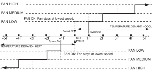
Staged Fan Operation With Temperature Demand:
- FAN ON: Fan stages from high to medium to low and stays continuously on in the lowest available speed.
- FAN AUTO: Fan stages from high to medium to low and cycles off at set point.
- FAN SPEED: is selected by the thermostat program.
- Single setpoint represented in drawing. Programming mode includes multiple setpoints.
Pipe Sensor Operation: A pipe sensor can be connected when the thermostat is configured for either 2-pipe or 4-pipe fan coil operation (see JP4 jumper configuration). The Pipe sensor is used to determine the water temperature in the Main Coil. The Pipe Sensor should be mounted on the Main Coil supply and wrapped with insulating material.
Pipe Sensor Input: 10K PECO Remote Probe or a standard On-Off Aqua-stat can be used for summer/winter changeover. ON (closed) is winter heating mode and OFF (open) is summer cooling mode.
Purge Cycle Operation: With a pipe sensor connected, this thermostat will initiate a purge cycle if the sensed water temperature is ambiguous (not adequately hot or cold). The purge cycle algorithm can be either temperature or time based, depending on the configuration of Service Menu 16.
Temperature-Based Purge:
- When an Ambiguous mode is detected and a demand exists, a 3 minute purge timer begins and the Main Output is opened.
- After the 3 minute purge cycle, the thermostat checks again to see if the water temperature is more than 15°F from set point, or above 80°F or below 60°F.
- If Winter or Summer mode is determined, normal HVAC operation occurs. If still ambiguous, the thermostat checks to see if the COIL temperature is below 60°F or above 80°.
Coil < 60°F = Summer Mode.
Coil > 80°F = Winter mode. - Purge Cycle is repeated until a non-ambiguous condition is sensed.
NOTE: If at any time the demand goes away, the thermostat will abort the purge cycle.
Time-Based Purge: (Default)
- The time-based purge cycle will start a 3-min purge cycle and enable the Main Output if any of the following conditions occur: transition from OFF to AUTO mode, Reset event, power cycle, and/or 1-hour timer expires.
- After the 3 min purge cycle, a pipe sensor reading says:
- Pipe is 15°F+ below the zone temp = Summer mode
- Pipe is 15°F+ above the zone temp = Winter mode
- Pipe is within 15°F of zone temp = still Ambiguous
- If a Winter or Summer mode is determined, the appropriate heating/cooling occurs. The thermostat will purge and check pipe temperatures again after 1-hour.
- If step 2 is still ambiguous, all thermostat outputs are disabled for 1 hour.
- After 1 hour, the purge cycle resumes at step 1.
HVAC Setback Systems
Setback Operation – Remove JP3
This is a low level input that is normally open. When switch is closed, the T180 heating and cooling setback limits are used as temperature control points. Fan operation in setback is cycled with demand. Pressing any button will override setback for 1 hour. Setback will override any user setting unless control is turned to OFF.
Intelligent Occupancy Sensors like the SD200-001 and SD200-002 can be used with this input to set the HVAC system to control at setback limits.
Occupancy Operation – Install JP3
The T180 can be used with PECO S200 series occupancy detection equipment. The occupancy and switch inputs are designed to connect to the SB200 slave sensor and SE200 door switch.
- The Occupancy Sensor is a low-level switch that is open when there is occupancy and closed when unoccupied.
- The Door Switch is a low-level switch that is open when the door is open and closed when the door is closed. This system requires both an Occupancy Sensor and a Door Switch.
Operation From an Occupied Mode:
- The T180 operates normally and looks for a door close. A door close signal initiates an occupancy status detection.
- If occupancy is detected, the T180 will maintain normal HVAC control. It then waits for a door open signal before determining occupancy again.
- If no occupancy signal is detected within 2 minutes, the T180 changes to unoccupied mode and controls at setback temperature values.
Operation From an Unoccupied Mode:
- In an Unoccupied State, the T180 sets heating and cooling set points to setback values, as determined in the service menu. In this mode, the fan is automatically set to cycle with demand.
- The T180 will continually monitor the room for occupancy.
- Any occupancy detection, including door open, will set the operation to occupied mode.
In either mode, if the door is left open for more than 2 minutes the T180 will disable the HVAC system. A one-time ten-minute override can be initiated by pressing any thermostat keypad.
Door Switch Only Operation
Install JP3. A stand-alone door or window switch can be connected to the T180 to disable the HVAC system (outputs) if a door or window is left open for more than 2 minutes. A one-time ten-minute override can be initiated by pressing any thermostat keypad.
Reference
Download Manual:
Peco TB180 Programmable Thermostat INSTALLATION INSTRUCTIONS
OTHER MANUALS
Peco TB180 Programmable Thermostat Owner Manual
Peco TB180 Programmable Thermostat INSTALLATION INSTRUCTIONS