TRANE 1H/1C(p/n X13511535-01) Programmable Thermostats
Introduction
This document provides installation, operation, and troubleshooting information for three Trane models of push-button thermostats:
- TheTrane Programmable 3-Heat/2-CoolThermostat:
- Trane PLM # X13511537-01
- Trane Clarksville part # BAYSTAT150A
- Service parts #THT02774
- TheTrane (non-programmable) 3-Heat/2-CoolThermostat:
- Trane PLM # X13511536-01
- Trane Clarksville part # BAYSTAT155A
- Service parts #THT02773
- TheTrane (non-programmable) 1-Heat/1-CoolThermostat:
- Trane PLM # X13511535-01
- Trane Clarksville part # BAYSTAT151A
- Service parts #THT02772
Note: To identify the thermostat type, locate the Terrane PLM # and the Terrane PLM #/Trane Clarksville # on the thermostat circuit board.
The information contained in this document applies to either one or two models or to all.
Differences are noted where appropriate. If no difference between models is noted, assume that all thermostat models share the information.
Product Features and Capabilities
The table below shows the functional differences between the three thermostat models.
| Thermostat Function or Feature | 1H/1C Thermostat (p/n X13511535-01) | 3H/2C Thermostat (p/n X13511536-01) | Programmable Thermostat
(p/n X13511537-01) |
| A liquid crystal display (LCD) with symbols for temperature, setpoints, and system operating modes. The programmable thermostat also has a day of the week, time of day, and occupancy settings. |  |
||
| System modes: Heat, Cool, Auto, Off. Both types of 3-Heat/2-Cool thermostats also have Emergency Heat mode. | |
|
|
| System Configuration Options. See “Configuration,” p. 26 for more information: | |||
| • 1-heat/1-cool, conventional | |
|
|
| • 1-heat/1-cool, heat pump without auxiliary heat | |
|
|
| • 1-heat only, conventional without fan | |
|
|
| • 1-heat only, conventional with fan | |
|
|
| • 1-cool, Conventional | |
|
|
| • 2-heat/1-cool, heat pump with auxiliary heat | |
|
|
| • 2-heat/2-cool, conventional | |
||
| • 2-heat/1-cool, conventional | |
|
|
| • 1-heat/2-cool, conventional | |
|
|
| • 2-heat/2-cool, heat pump without auxiliary heat | |
|
|
| • 3-heat/2-cool, heat pump with auxiliary heat | |
|
|
| A heating and cooling setpoint range of 40ºF to 90ºF (4.5ºC to 32ºC) | |
|
|
| Two fan modes: On, Auto | |
|
|
| Additional configurable options (See “Configuration,” p. 26) | |
|
|
| Terminals and configuration options for a remote temperature sensor. Options include: | |||
| • Displaying the remote/outdoor temperature on the LCD | |
||
| • Using the remote/outdoor temperature to lockout the compressor or auxiliary heat | |
||
| • Using the remote/outdoor temperature instead of the built-in sensor | |
||
| Scheduling function with two or four periods per day and the following day/week options: | |||
| • 5/2 day schedule: weekdays share a schedule; Saturday and Sunday share a schedule | |
||
| • 5/1/1 day schedule: weekdays share a schedule; Saturday and Sunday have their own, independent schedules | |
||
| • 1-day schedule: Every day shares the same schedule | |
||
| • 7-day schedule: Each day has its own, independent schedule | |
||
| Temporary override function with a configurable override time limit | |
Dimensions
Figure 1 and Figure 2 provide dimensions for each type of thermostat. The two non-programmable thermostats have the same dimensions; the programmable thermostat has slightly different dimensions.
Figure 1. ProgrammableThermostat Dimensions

Note: Drawing not to scale. Dimensions within ± 0.02 in. (± 0.5 mm)
Figure 2. 1-Heat/1-Cool or 3-Heat/2-Cool (non-programmable)Thermostat Dimensions

Note: Drawing not to scale. Dimensions within ± 0.02 in. (± 0.5 mm)
Pre-Installation
This section provides the following pre-installation information:
- Location considerations
- Height requirements
- Mounting surfaces
- Maximum wire length
Location Considerations
When selecting a location, avoid the following:
- Areas of direct sunlight
- Areas in the direct airstream of air diffusers
- Exterior walls and other walls that have a temperature differential between the two sides
- Areas that are close to heat sources such as sunlight, appliances, concealed pipes, chimneys, or other heat-generating equipment
- Drafty areas
- Dead spots behind doors, projection screens, or corners
- Walls that are subject to high vibration
- Areas with high humidity
- High traffic areas (to reduce accidental damage or tampering)
Height Requirements
It is recommended that you mount the back plate a maximum distance of 54 in. (137 cm) above the floor. If a parallel approach by a person in a wheelchair is required, reduce the maximum height to 48 inches.
Note: Consult section 4.27.3 of the 2002Americans with DisabilityAct guideline, and local building codes, for further details regarding wheelchair requirements.
Mounting Surfaces
The thermostat can be mounted to any sturdy, vertical surface. Plastic threaded anchors and M3.5 x 20 mm screws are provided for mounting to plaster or wallboard; 6-32 x 3/4 inch machine screws are provided for mounting directly to a standard electrical device box. Other fastener varieties may be required for other surface types.
When replacing a horizontally mounted thermostat and there is an adapter kit available to cover any opening in the wall. Contact your local Trane office for more information.
MaximumWire Lengths
Thermostat to HVAC Equipment
The thermostat may not function properly if the total resistance of any of the thermostat to HVAC equipment wires exceeds 2.5 ohms.To ensure that wire length does not cause excess resistance, refer to Table 1 and ensure that the wires from the thermostat to the HVAC equipment are not too long.
Table 1. MaximumThermostat to HVAC Equipment Wire Lengths
| Copper wire size | Maximum recommended wire length |
| 22 AWG (0.33 mm2) | 150 ft (46 m) |
| 20 AWG (0.50 mm2) | 240 ft (73 m) |
| 18 AWG (0.75 mm2) | 385 ft (117 m) |
Remote Sensor to ProgrammableThermostat
Because remote temperature sensors measure resistance, very long cable runs can cause slight errors in the measurement. For the highest temperature reading accuracy, avoid exceeding the maximum recommended wire lengths shown in Table 2.
Table 2. Maximum Recommended Remote Sensor Wire Length
|
Copper wire size |
Maximum recommended remote sensor wire length |
| 22 AWG (0.33 mm2) | 1000 ft (300 m) |
| 20 AWG (0.50 mm2) | 1500 ft (450 m) |
| 18 AWG (0.75 mm2) | 2500 ft (750 m) |
Note: For 22 AWG (0.33 mm2) copper wires, the rate of error can be up to 0.5 °F (0.3 °C) per 100 ,which typically requires wire lengths in excess of 5000 ft (1500 m).
Installation
This section provides installation instructions.
Before you begin, read through the pre-installation information, beginning on p. 9, and also verify the following conditions are met:
- A wire access hole is available at the thermostat location.
- The wires are accessible through the hole.
- The wires are attached to the appropriate terminals on the HVAC equipment.
- There is continuity (and not more than 2.5 ohms resistance) between the thermostat location and the HVAC equipment.
- The wires are accurately labeled or identified by color.
Mounting the Back Plate
WARNING
Hazardous voltage! Disconnect all electric power, including remote disconnects before servicing. Follow proper lockout/tagout procedures to ensure the power cannot be inadvertently energized. Failure to disconnect power before servicing could result in death or serious injury.
NOTICE
Equipment damage!
Applying excessive voltage to the thermostat will permanently damage it.
To mount the back plate:
- Shut off power to the HVAC equipment.
Note: If the security screw is installed, remove it before attempting to remove the cover. See Figure 3.
- Remove the cover by firmly pressing the thumb tab at the bottom of the cover and pulling the cover away from the back plate.
- Feed the wires through the opening in the back plate.

- If you are mounting the back plate directly to a wall surface, hold the back plate against the surface and mark the fastener locations.
- Secure the back plate using appropriate fasteners. (See “Mounting Surfaces,” p. 9.)The thermostat must be level and plumb for accurate temperature control and to ensure proper air movement through the thermostat enclosure.
Wiring
WARNING
Hazardous voltage!
Disconnect all electric power, including remote disconnects before servicing. Follow proper lockout/tagout procedures to ensure the power cannot be inadvertently energized. Failure to disconnect power before servicing could result in death or serious injury.
NOTICE
Equipment damage!
Applying excessive voltage to the thermostat will permanently damage it.
General Practice
To wire the thermostat:
- Connect the wires to the terminal block(s) packaged in the box with the thermostat. (The programmable thermostat has two terminal blocks, the non-programmable thermostats have only one):
- Remove approximately 1/4 inch (6 mm) of insulation from the wires.
- Use the terminal block screws to securely fasten each wire into the terminal block.
- Refer to the section, “Terminal Identification,” p. 13, and the wiring diagrams on the pages that follow to determine the correct terminal for each wire.
Note: In some cases, the terminal labels (Y, G, R, etc.) correctly correspond to the first letter of the color wire to which they are connected. However, you must verify which equipment terminals are connected at the other ends of the wires before connecting the wires to the thermostat.
- Align the pins on the circuit board with the holes on the bottom of the terminal blocks and gently push the wired terminal blocks into place on the circuit board. See Figure 5.
Figure 5. Attaching the wired terminal blocks to the pins on the circuit board
- Push the excess wire through the hole in the wall cavity or into the junction box.
Important: Do not coil excess wire between the thermostat and the back plate. - Use non-flammable insulation to prevent air movement between the wall cavity and the thermostat.
Terminal Identification
The table below defines the terminals for each of the thermostat types. Where present:
| Terminal Label Terminal Description | 1H/1C Thermostat (p/n X13511535-01) | 3H/2C Thermostat (p/n X13511536-01) | Programmable Thermostat
(p/n X13511537-01) |
| C Common | |||
| G Fan Relay | |||
| Y Stage 1 compressor control | |||
| W (O/B) Heat relay (Changeover valve)(1) | |||
| Rc:24Vac cooling:These terminals are shipped with a jumper connected R:24Vac heating between them. Remove the jumper if the 24Vac power supplies are separate. |
|||
| W2 (W1) Second stage heat (Auxiliary heat or emergency heat relay.)(1) or W2 (Aux/E) | |||
| Y2 Stage 2 compressor control | |||
| A Economizer | |||
| S1 External sensor | |||
| S2 External sensor | |||
| (L) (Emergency heat indicator)(1) |
Wiring Diagrams
The following diagrams show all of the common wiring scenarios you are likely to encounter.
1-Heat/1-CoolThermostat
Use Table 3 and the diagrams that follow to correctly wire the thermostat for your system type.
Table 3. SystemType Options for 1H/1C Non-ProgrammableThermostats
| System Type | Value for Option 01 | See Diagram |
| 1-heat/1-cool, conventional | 0 | Figure 6 |
| 1-heat/1-cool, heat pump without auxiliary heat | 1 | Figure 7 |
| 1-heat only, conventional without fan | 2 | Figure 8 |
| 1-heat only, conventional with fan | 3 | Figure 9 |
| 1-cool, Conventional | 4 | Figure 10 |


3-Heat/2-Cool Non-programmable thermostat
Use Table 4 and the diagrams that follow to correctly wire the thermostat for your system type.
Table 4. SystemType Options for 3H/2C Non-ProgrammableThermostats
| System Type | Value for Option 01 | See Diagram |
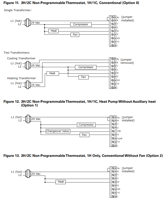
| 1-heat/1-cool, conventional | 0 | Figure 11 |
| 1-heat/1-cool, heat pump without auxiliary heat | 1 | Figure 12 |
| 1-heat only, conventional without fan | 2 | Figure 13 |
| 1-heat only, conventional with fan | 3 | Figure 14 |
| 1-cool, Conventional | 4 | Figure 15 |
| 2-heat/1-cool, heat pump with auxiliary heat | 5 | Figure 16 |
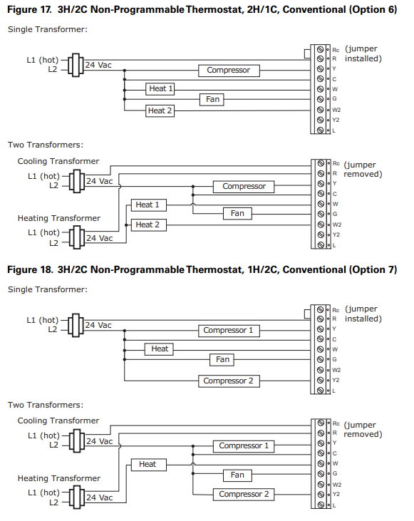
| 2-heat/1-cool, conventional | 6 | Figure 17 |
| 1-heat/2-cool, conventional | 7 | Figure 18 |
| 2-heat/2-cool, heat pump without auxiliary heat | 8 | Figure 19 |
| 3-heat/2-cool, heat pump with auxiliary heat | 9 | Figure 20 |


Programmable Thermostat
Use Table 5 and the diagrams that follow to correctly wire the thermostat for your system type.
Table 5. SystemType Options for ProgrammableThermostats
| System Type | Value for Option 130 | See Diagram |
| 1-heat/1-cool, conventional | 1 | Figure 21 |
| 1-heat/1-cool, heat pump without auxiliary heat | 2 | Figure 22 |
| 1-heat only, conventional without fan | 3 | Figure 23 |
| 1-heat only, conventional with fan | 4 | Figure 24 |
| 1-cool, conventional | 5 | Figure 25 |
| 2-heat/1-cool, heat pump with auxiliary heat | 6 | Figure 26 |
| 2-heat/2-cool, conventional | 7 | Figure 27 |
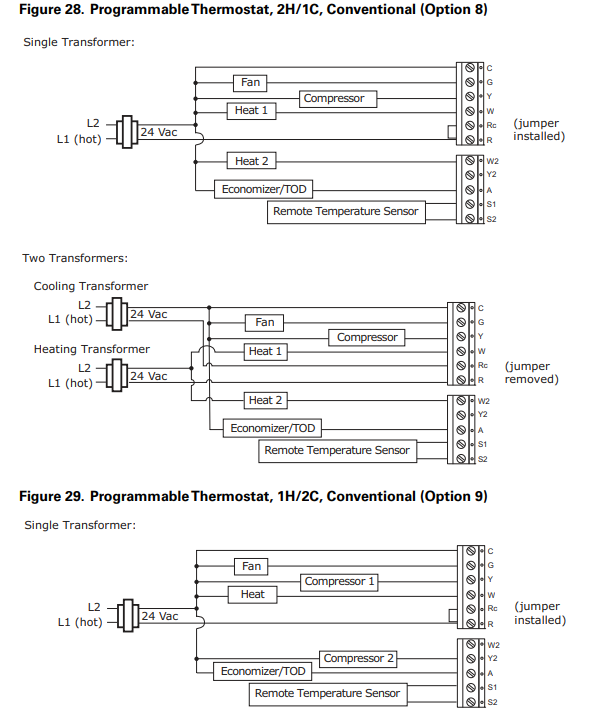
| 2-heat/1-cool, conventional | 8 | Figure 28 |
| 1-heat/2-cool, conventional | 9 | Figure 29 |
| 2-heat/2-cool, heat pump without auxiliary heat | 10 | Figure 30 |
| 3-heat/2-cool, heat pump with auxiliary heat | 11 | Figure 31 |


Replacing the Cover
To replace the cover:
- Hook the cover over the top of the back plate. Apply light pressure to the bottom of the cover until it snaps in place.
- If desired, install the security screw into the bottom of the cover. See Figure 32.
Figure 32. Close cover – insert security screw
Applying Power
Applying power to the thermostat will initiate a power up sequence.
- The full screen appears for 1.5 seconds.
- The firmware version appears for 1.5 seconds:
- On the programmable thermostat, the firmware version shows in the HH:MM digits.
- On the non-programmable thermostats, the digits are split between the top and bottom regions of the screen: the most significant digits are at the top.
- Power up tests are performed.
- If an error is detected, an error code appears (see “Error Codes,” p. 43).
- If no errors are detected, the home screen appears (see Figure 33).

Configuration
NOTICE
Adverse Control System Behavior!
Improper configuration could cause unwanted, possibly adverse control system behavior. Be sure to configure the thermostat according to your system type.
To change the installation configuration:
- Apply electrical power to the thermostat.
- See the appropriate table for your thermostat type to determine the configuration options you need:
- Table 6, p. 27 for 3-Heat/2-Cool programmable thermostats
- Table 7, p. 31 for 3-Heat/2-Cool non-programmable thermostats
- Table 8, p. 32 for 1-Heat/1-Cool, non-programmable thermostats
- Write down your selections or other notes on the table.
- Enter installer configuration mode:
WARNING
Live Electrical Components!
The circuit board is energized. Have a qualified licensed electrician or other individual who has been properly trained in handling live electrical components perform this step. Failure to follow all electrical safety precautions when exposed to live electrical components could result in death or serious injury.- Remove the thermostat cover.
- Press and hold the configuration button for at least 3 sec.

- Press
 ,
,  or
or  to scroll through the options, identified by their numbers, until you reach the option you want to change:
- scrolls to a lower-numbered option.
- or scrolls to a higher-numbered option.
- Use or to change the value of the option:
 decreases the value.
 increases the value.
- Repeat Step 5 and Step 6 until you have made all necessary changes.
Note: Values are saved in permanent memory after setting a value and moving to next configuration parameter, and also when you exit configuration mode. - Do one of the following to exit configuration mode:
- Remove the thermostat cover, if necessary, and then press and immediately release the configuration button.
- Do not press any buttons for 10 min.
- Press and hold for 2 sec.
Table 6. Installation Options for 3-Heat/2-Cool Programmable Thermostat
| No. | Name | Default | Opts. | Descriptions |
| 0100 | Temperature | 0 | 0 | °F, 1 degree resolution |
| indication/ resolution | 1
2 |
°F, 0.5 degree resolution
°C, 1 degree resolution |
||
| 3 | °C with 0.5 degree resolution | |||
| 4 | °C with 0.1 degree resolution | |||
| 0110 | Clock format | 12 | 12 | 12 hour clock |
| 24 | 24 hour clock | |||
| 0120 | Year | 09 | 09-99 | 2009 – 2099 |
| 0121 | Month | 1 | 1-12 | Months of the year |
| 0122 | Day | 1 | 1-31 | Days of the month |
| 0125 | Daylight savings | 2 | 0 | Disabled |
| 1 | US (1987), changeover at 2:00am | |||
| 2 | US (2007), changeover at 2:00am | |||
| 3 | Europe, changeover at 1:00am | |||
| 4 | Manual, changeover at 2:00am | |||
| 0126 | Spring month(1) | 03 | 01-12 | The month in which the Spring daylight savings change occurs |
| 0127 | Spring day | 08 | 01-31 | The day on which the Spring daylight savings change occurs |
| 0128 | Fall month | 11 | 01-12 | The month in which the Fall daylight savings change occurs |
| 0129 | Fall day | 08 | 01-31 | The day on which the Fall daylight savings change occurs |
| 0130 | System selection | 8 | 1 | 1H/1C (conv) 1st Stage Heat (W), 1st Stage Comp (Y), Fan (G) |
| 2 | 1H/1C (HP) 1st Stage Comp (Y), Changeover (O/B), Fan (G) | |||
| 3 | 1H (Conv) 1st Stage Heat (W), without fan | |||
| 4 | 1H (Conv) 1st Stage Heat (W), Fan (G) | |||
| 5 | 1C (Conv) 1st Stage Comp (Y), Fan (G) | |||
| 6 | 2H/1C (HP) 1st Stage Comp (Y), Changeover (O/B), Auxiliary Heat (W1), Fan (G) | |||
| 7 | 2H/2C (Conv) 1st & 2nd Stage Heat (W,W2), 1st & 2nd Stage Comp (Y,Y2), Fan (G) | |||
| 8 | 2H/1C (Conv) 1st & 2nd Stage Heat (W,W2), 1st Stage Comp (Y), Fan (G) | |||
| 9 | 1H/2C (Conv) 1st Stage Heat (W), 1st & 2nd Stage Comp (Y,Y2), Fan (G) | |||
| 10 | 2H/2C (HP) 1st & 2nd Stage Comp (Y,Y2), Changeover (O/B), Fan (G) | |||
| 11 | 3H/2C (HP) 1st & 2nd Stage Comp (Y,Y2), Changeover (O/B), Auxiliary Heat (W1), Fan (G) |
| No. | Name | Default | Opts. | Descriptions |
| 0140 | Schedule options | 1 | 0
1 |
Non-programmable
Programmable |
| 0150 | TOD/Economizer output
(terminal A) |
0 | 0
1
2 |
Unused
TOD energizes terminal A during occupied period, not during unoccupied period. Economizer energizes terminal A during a call for cool |
| 0151 | Heat fan operation | 0 | 0
1 |
System controls fan
Thermostat controls fan |
| 0153 | Reversing value O/B | 0 | 0
1 |
O/B terminal energized in cooling
O/B terminal energized in heating |
| 0160 | CPH 1st stage compressor(2) | 3 | 1-5 | Cycles per hour for 1st stage compressor – only for systems with cool or heat pump stage – also changes 2nd stage cool default CPH |
| 0161 | CPH 2nd stage compressor(2) | 3 | 1-5 | Cycles per hour for 2nd stage compressor – only for systems with two cool or heat pump stages |
| 0162 | CPH 1st stage conventional heat(2) | 5 | 1-10 | Cycles per hour for 1st stage conventional heat – only for systems with heat stages – also changes 2nd stage heat default CPH |
| 0163 | CPH 2nd stage conventional heat(2) | 9 | 1-10 | Cycles per hour for 2nd stage conventional heat – only for systems with two conventional heat stages |
| 0164 | CPH for auxiliary heat(2) | 9 | 1-10 | Cycles per hour for auxiliary heat – only for heat pump systems with more heat than cool stages |
| 0165 | CPH for emergency heat(2) | 9 | 1-10 | Cycles per hour for emergency heat – only for heat pump systems with more heat than cool stages |
| 0170 | Continuous backlight | 0 | 0
1 |
Backlight “ON” time is limited
Backlight does not turn off |
| 0180 | Changeover | 1 | 0
1 |
Manual changeover (heat/cool/off) – manually changeover the thermostat between heat, cool, and off
Auto changeover (heat/cool/auto/off) – manually changeover between heat, cool, and off, or select automatic changeover |
| 0181 | Deadband(3) | 3 | 2
3 4 5 6 7 8 9 |
2° F (1° C)
3° F (1.5° C) 4° F (2.0° C) 5° F (2.5° C) 6° F (3.0° C) 7° F (3.5° C) 8° F (4.0° C) 9° F (4.5° C) |
| 0182 | Minimum compressor off time | 5 | 0-5 | Minutes for compressor off time – for systems with cool or heat pump stages
– (Minutes specified here are added to the 5 min base off time.) |
| 0190 | Power supply frequency | 0 | 0
1 |
60Hz
50 Hz |
| 0210 | Temperature sensor selection | 0 | 0
1
2
3 |
Internal for H/C – display can show only local temperature and setpoint
Internal for H/C – remote (connected to S1 & S2)(4) for display – display can show local and remote temperature, and setpoint Internal for H/C, remote (connected to S1 & S2)(4) for compressor and auxiliary lockout; display can show local and remote temperature, and setpoint – (Disabled for conventional systems.) Remote (connected to S1 & S2)(4) for H/C, internal disabled; display can show remote indoor temperature and setpoint |
| No. | Name | Default | Opts. | Descriptions |
| 0220 | Heat pump compressor lockout point(5) | 0 | 0
15 20 25 30 35 40 45 |
None
15° F (–9.5° C) 20° F (–6.5° C) 25° F (–4.0° C) 30° F (–1.0° C) 35° F (1.5° C) 40° F (4.5° C) 45° F (7.0° C) |
| 0221 | Heat pump aux lockout point | 0 | 0
40 45 50 55 60 |
None
40° F (4.5° C) 45° F (7.0° C) 50° F (10.0° C) 55° F (13.0° C) 60° F (15.5° C) |
| 0230 | Temp occupied duration limit for TOV override | 3 | 0
1 2 3 4 |
0 hours (Note: TOV function is still available)
1 hour 2 hours 3 hours 4 hours |
| 0231 | Number of periods | 2 | 2
4 |
Two scheduling periods per day
Four scheduling periods per day |
| 0232 | Period occupied/ unoccupied definitions | 4 | If Option #0231 is set to 2: | |
|
0 1 2 3 4 5 6 7 8 9 10 11 12 13 14 15 |
Day Night
Unoccupied Unoccupied Unoccupied Occupied Unoccupied Unoccupied Unoccupied Occupied Occupied Unoccupied Occupied Occupied Occupied Unoccupied Occupied Occupied Unoccupied Unoccupied Unoccupied Occupied Unoccupied Unoccupied Unoccupied Occupied Occupied Unoccupied Occupied Occupied Occupied Unoccupied Occupied Occupied |
|||
| If Option #0231 is set to 4: | ||||
|
0 1 2 3 4 5 6 7 8 9 10 11 12 13 14 15 |
Morning Day Evening Night
Unoccupied Unoccupied Unoccupied Unoccupied Unoccupied Unoccupied Unoccupied Occupied Unoccupied Unoccupied Occupied Unoccupied Unoccupied Unoccupied Occupied Occupied Unoccupied Occupied Unoccupied Unoccupied Unoccupied Occupied Unoccupied Occupied Unoccupied Occupied Occupied Unoccupied Unoccupied Occupied Occupied Occupied Unoccupied Unoccupied Unoccupied Unoccupied Occupied Unoccupied Unoccupied Occupied Occupied Unoccupied Occupied Unoccupied Occupied Unoccupied Occupied Occupied Occupied Occupied Unoccupied Unoccupied Occupied Occupied Unoccupied Occupied Occupied Occupied Occupied Unoccupied Occupied Occupied Occupied Occupied |
|||
| No. | Name | Default | Opts. | Descriptions |
| 0233 | Scheduling mode day options | 0 | 0
1
2 3 |
1 day – Mo-Su share the same schedule
5+1+1 days – Mo-Fr share a schedule; Sa and Su each have an independent schedule 5+2 days – Mo-Fr share a schedule; Sa-Su share a schedule 7 days – Each day has an independent schedule |
| 0240 | Heat temperature range stops(6) | 90 | 40 – 90
4 – 32 |
40° F to 90° F
4° C to 32° C |
| 0241 | Cool temperature range stops(7) | 50 | 50 – 99
10 – 37 |
50° F to 99° F
4° C to 32° C |
| 0260 | Temperature display offset(8) | 0 | -3
-2 -1 0 1 2 3 |
–3° F (–1.5° C)
–2° F (–1.0° C) –1° F (–0.5° C) None 1° F (0.5° C) 2° F (1.0° C) 3° F (1.5° C) |
| 0270 | Extended fan-on time heat(9)(10) | 0 | 0
90 |
Off
90 sec |
| 0271 | Extended fan-on time cool(9)(7) | 0 | 0
40 |
Off
40 sec |
| 0300 | Restore factory defaults | 0 | 0
1 |
No – do not restore
Yes – reset all installer options to default except calendar, and system selection – options 0120-0122 and 0125-0130 do not reset. |
- Only available if option #0125 is set to 4.
- See “Heat and Cool Cycling Rate,” p. 41.
- See “Deadband,” p. 41.
- If an external sensor is attached to the S1 and S2 terminals, it must be a 10K negative temperature coefficient.
- Only available for heat pump systems with more heat than cool stages and remote outdoor sensor. A 5 °F (2.5 °C) dead band between options #0220 and #0221 will be enforced automatically.
- Only applies to systems with heat stages.
- Only applies to systems with cool stages.
- Only applies to control temperature and display temperature for internal and indoor remote sensor. Does not apply to outdoor temperature for display.
- See “Extended Fan-on Time (Heat or Cool),” p. 42.
- Only available when option #0151 is set to 1.
Table 7. Installation Options for 3-Heat/2-Cool Non-Programmable Thermostat
| No. | Name | Default | Opts. | Descriptions |
| 01 | System type | 0 | 0
1
2 3 4 5
6 7 8
9 |
1H/1C, conventional – 1st stage heat (W), 1st stage compressor (Y)
1H/1C, heat pump without auxiliary heat – 1st stage compressor (Y), changeover (O/B) 1H, conventional without fan – 1st stage heat (W) 1H, conventional with fan – 1st stage heat (W), fan (G) 1C, conventional – 1st stage compressor (Y) 2H/1C, heat pump with auxiliary heat – 1st stage compressor (Y), changeover (O/B), auxiliary heat (Aux/E) 2H/1C, conventional – 1st & 2nd stage heat (W,W2), 1st stage compressor (Y) 1H/2C, conventional – 1st stage heat (W), 1st & 2nd stage compressor (Y, Y2) 2H/2C, heat pump without auxiliary heat – 1st & 2nd stage compressor (Y, Y2), changeover (O/B) 3H/2C, heat pump with auxiliary heat – 1st & 2nd stage compressor (Y, Y2), changeover (O/B), auxiliary heat (Aux/E) |
| 02 | Changeover valve | 0 | 0
1 |
O/B terminal energized in cooling
O/B terminal energized in heating |
| 03 | Fan control(1) | 0 | 0
1 |
Gas or oil furnace, equipment controls fan for heating
Electric furnace, thermostat controls fan in heating |
| 04 | Stage 1 heat cycle rate(2) | 5 | 1-10 | Cycles per hour for 1st stage conventional heat – only available on systems with conventional heat |
| 05 | Stage 1 compressor cycle rate(2) | 3 | 1-5 | Cycles per hour for 1st stage compressor – only available on systems with cool stages |
| 06 | Manual/Auto changeover | 0 | 0
1
2 |
Manual changeover (heat/cool/off) – manually changeover between heat, cool, and off
Auto changeover (heat/cool/auto/off) – manually changeover between heat, cool, and off, or select automatic changeover Auto changeover only (auto) – no manual changeover |
| 07 | Temperature indication/ resolution | 0 | 0
1 2 3 4 |
°F with 1 degree resolution
°F with 0.5 degree resolution °C with 1 degree resolution °C with 0.5 degree resolution °C with 0.1 degree resolution |
| 08 | Compressor protection | 5 | 0-5 | Minutes for compressor off time – only available on heat pump systems or systems with cool stages – (Minutes specified here are added to the 5 min base off time.) |
| 09 | Heat temperature range stop | 90 | 40-90 | Heating high temperature range stop in °F. (4.5-32°C) |
| 10 | Cool temperature range stop | 50 | 50-99 | Cooling low temperature range stop in °F. (10-37°C) |
| 11 | Power supply frequency | 0 | 0
1 |
60 Hz
50 Hz |
| 12 | Deadband(3) | 3 | 2
3 4 5 6 7 8 9 |
2°F (1.0°C)
3°F (1.5°C) 4°F (2.0°C) 5°F (2.5°C) 6°F (3.0°C) 7°F (3.5°C) 8°F (4.0°C) 9°F (4.5°C) |
| 13 | Stage 2 heat cycle rate(2) | 9 | 1-10 | Cycles per hour for 2nd stage conventional heat – only available for conventional systems with at least two stages conventional heat |
| 14 | Auxiliary heat cycle rate(2) | 5 | 1-10 | Cycles per hour for auxiliary heat – only for heat pump systems with more heat than cool stages |
| 15 | Emergency heat cycle rate(2) | 5 | 1-10 | Cycles per hour for emergency heat – only for heat pump systems with more heat than cool stages. |
| 16 | Stage 2 compressor cycle rate(2) | 3 | 1-5 | Cycles per hour for 2nd stage compressor – only for systems with two cool stages |
| 17 | Auxiliary heat control | 0 | 0
1 |
Comfort
Economy |
| 18 | Restore factory defaults | 0 | 0
1 |
No – do not reset
Yes – reset all installation configurations (all settings in this table) to default settings, except System selection |
- These options only available on systems with fans.
- See “Heat and Cool Cycling Rate,” p. 41.
- See “Deadband,” p. 41. For auto or manual systems (see Option 01).
Table 8. Installation Options for 1-Heat/1-Cool Non-Programmable Thermostat
| No. | Name | Default | Opts. | Descriptions |
| 01 | System type | 0 | 0
1 2 3 4 |
1H/1C, conventional -1st stage heat (W), 1st stage compressor (Y)
1H/1C, heat pump – 1st stage compressor (Y), changeover (O/B) 1H, conventional, without fan – 1st stage heat (W) 1H, conventional with fan -1st stage heat (W), fan (G) 1C, conventional – 1st stage compressor (Y) |
| 02 | Changeover valve | 0 | 0
1 |
O/B terminal energized in cooling
O/B terminal energized in heating |
| 03 | Fan control(1) | 0 | 0
1 |
Gas or oil furnace, equipment controls fan for heating
Electric furnace, thermostat controls fan in heating |
| 04 | Stage 1 heat cycle rate(2) | 5 | 1-10 | Cycles per hour for 1st stage conventional heat – only available on systems with conventional heat |
| 05 | Stage 1 compressor cycle rate(2) | 3 | 1-5 | Cycles per hour for 1st stage compressor – only available on systems with cool stages |
| 06 | Manual/Auto changeover | 0 | 0
1
2 |
Manual changeover (heat/cool/off) – manually changeover between heat, cool, and off
Auto changeover (heat/cool/auto/off) – manually changeover between heat, cool, and off, or select automatic changeover Auto changeover only (auto) – no manual changeover |
| 07 | Temperature indication/ resolution | 0 | 0
1 2 3 4 |
0°F with 1 degree resolution
°F with 0.5 degree resolution °C with 1 degree resolution °C with 0.5 degree resolution °C with 0.1 degree resolution |
| 08 | Compressor protection | 5 | 0-5 | Minutes for compressor off time – only available on heat pump systems or systems with cool stages – (Minutes specified here are added to the 5 min base off time.) |
| 09 | Heat temperature range stop | 90 | 40-90 | Heating high temperature range stop in °F. (4.5-32°C) |
| 10 | Cool temperature range stop | 50 | 50-99 | Cooling low temperature range stop in °F. (10-37°C) |
| 11 | Power supply frequency | 0 | 0
1 |
60 Hz
50 Hz |
| 12 | Deadband(3) | 3 | 2
3 4 5 6 7 8 9 |
2°F (1.0°C)
3°F (1.5°C) 4°F (2.0°C) 5°F (2.5°C) 6°F (3.0°C) 7°F (3.5°C) 8°F (4.0°C) 9°F (4.5°C) |
| 18 | Restore factory defaults | 0 | 0
1 |
No – do not reset
Yes – reset all installation configurations (all settings in this table) to default settings, except System selection |
- These options only available on systems with fans.
- See “Heat and Cool Cycling Rate,” p. 41.
- See “Deadband,” p. 41. For auto or manual systems (see Option 01).
REFERENCE
DOWNLOAD MANUALS:
TRANE 1H1C(pn X13511535-01) Programmable Thermostats Installation MANUAL
OTHER MANUALS:
TRANE 1H/1C(p/n X13511535-01) Programmable Thermostats Operation MANUAL
![]()
TRANE 1H/1C(p/n X13511535-01) Programmable Thermostats Installation MANUALS