Micro-Air 347 Touch Screen Thermostat

EasyTouch RV 347 Models and Compatible Replacements
The EasyTouch 347 model thermostats were designed to directly replace certain GE™ model RV thermostats. EasyTouch RV 347 can be purchased in two colors, as shown in Table 1.
| EasyTouch RV 347 Model | Color |
| ASY-347-X01 | Black |
| ASY-347-X02 | White |
Model Compatibility
Table 2 lists the known OEM model numbers that can be used with EasyTouch RV 347. The tables are not exhaustive so if your thermostat is not listed, please contact Micro-Air https://www.microair. com/SupportRequest to verify if this is the correct model for your application. Thermostat model numbers can be found in your original user’s manual and on the back side of the thermostat or the back of the mounting plate. Note that a “ * ” character means any character in that position is a match
| Compatible OEM Thermostats |
| RARWT * * |
| RARMC * * |
| RAREC3A |
| RAREC2A |
| RAREC1A |
Installing the Thermostat
Safety
First, it is recommended to remove both AC and DC power from your system. Unplug your RV from shore power and turn off any converters or generators to remove AC power. Open your 12-volt DC bus breaker or fuse to de-energize your thermostat. This greatly reduces the chance of any harmful electrical discharge, as well as preventing accidentally opening a fuse
Removing the Old Thermostat
Pry open the thermostat using a small screwdriver on the visible seam on the bottom, top and sides. The display part will disconnect and allow the thermostat to be turned around to reveal the wiring connections. Take care not to pull out the wires as you remove them from the wall. The thermostat’s circuit board will remain attached to the front side of the thermostat. Take note of the three wires leading into the wall of the RV.
Before removing the wiring, write down the color of the wire and the terminal to which each wire connects. We recommend taking a picture of the wiring before removal. GE’s wire terminals are labeled: GND, COMMS and +12V. Release each wire from its connection by unscrewing each small screw on the terminal block. Remove the wall attachment screws from the wall bracket forming the back half of the GE thermostat. Tape the wires to the wall to avoid losing them in the opening.
Using the push button terminals
Figure 1 shows a screwdriver depressing the push button connector. The silver gate is opened for the wire to be inserted. Releasing the button traps the wire and makes the connection.
Remove approximately 3/8 inch (1cm) of insulation from the wire to be inserted. Use a small screwdriver (not provided) or similar tool to push down on the square push button. Insert the wire in the insertion space and press the push button. Verify the connection by gently pulling on the wire. Do not force excessive wire down into the connector. If the stripped wire end is longer than 3/8 inch, cut the end so there is no bare wire sticking out when properly inserted.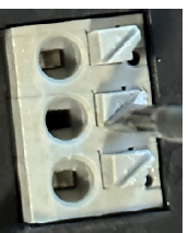
Wiring the Thermostat
There are three terminals on the back of EasyTouch RV Model 347 labeled SIG, GND, and 12V. They will be connected to the push terminals on the back of the EasyTouch thermostat. Use the information in Table 1 to determine the connections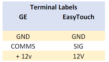
Apply Power
Turn on any converter or power circuit that was turned off to install the thermostat.
Mounting the Thermostat
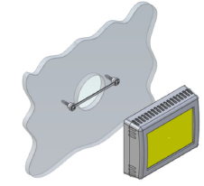
- Step 1: Locate the mounting buttons horizontally across the hole with the smaller diameter against the wall
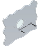
- Step 2: Screw in one screw and level the buttons so the display will be straight when installed.
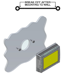
- Step 3: Screw in second screw making sure the two buttons remain level.
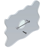
- Step 4: Remove mounting tab before mounting on the wall.
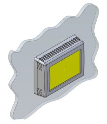
- Step 5: Aligning the buttons with the holes in the back of the display. Press the display against the wall and gently slide the display down to lock it in place.
Initial Setup Instructions
Configure your available heat sources
EasyTouch RV 347 must be configured for your system prior to using it. Tap the Settings button on the main screen, then navigate to the Setup button and tap it. Tap the heat pump button and/or the furnace button to enable or disable it based on what is installed in your system. A red circle with a line through it over the button indicates disabled.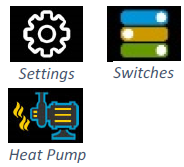
Gas Assist Enable/Disable
Systems that have both a gas furnace and a heat pump can use the gas assist feature. This feature determines if the heat pump cannot keep up with demand and assists or overrides the heat pump operation. Enable or disable this feature using the provided button.
Connecting Remotely
EasyTouch RV can be operated entirely by the touchscreen, however you can also communicate, monitor, and modify operation of it wirelessly using the EasyTouch RV application. Software updates, time updates, and some other features will require a wireless connection. Download the app from Google Play or and Apple App store. Look for the icon shown on the left.

Operating Instructions
Please see our Knowledge Bank for the separate operating manual containing additional information on operating this control.
EasyTouch RV Knowledge Bank – More Information
Visit our knowledge bank at http://www.micro-air.com/kb_easytouch_rv.cfm for the latest resources for setup, operation, and troubleshooting, as well as our main website for contacting us for support.
REFERENCE:
DOWNLOAD MANUALS:
Micro-Air 347 Touch Screen Thermostat Operating Manual
![]()