
![]()
SALUS SC102ZB Wireless Fan Coil Thermostat
Notices
Please read these instructions carefully before installing and using the Wireless Fan Coil Controller.
- Follow all local and electricity supplier regulations regarding the installation or replacement of a thermostat. An authorized, qualified installer may be required.
- Do not connect any of the terminals to a 120/240 VAC supply. The Wireless Fan Coil Controller uses a 24 VAC power source.
- Do not cover any of the vents on the thermostat.
- Do not place the unit in a bathroom or area of excessive moisture.
- Do not allow the unit to get wet. This device serves as a temperature control system only in dry, closed living and office spaces.
- Do not use solvents or aggressive cleaning agents. A dry, soft cloth is recommended.
Let’s Get Started
Make sure you have the following items: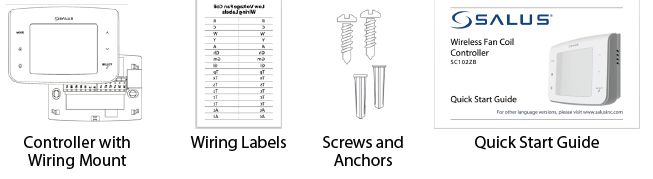
Tools:
- #1 Phillips or flathead screwdriver
- Drill with 3/16” bit (only if you need to use anchors)
Optional Tools
- Smartphone or digital camera to take picture of wiring for later reference
- Screwdriver to disconnect wires from old thermostat
- Pencil
Turn Off Power to the Fan Coil System
This is usually accomplished by turning off the circuit breaker in the breaker panel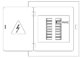
Determine Wiring Configuration
- Remove the old thermostat from the wall to expose the wiring terminals.
- Take a picture of the wiring for future reference.
- Note the terminals attached to each wire and attach the matching label to the ends of the wires.
Use the following table as reference
| Terminal Name | Function | |
| 4 pipe system | 2 pipe system | |
| R | 24VAC input | |
| C | Common of AC input | |
| WY | Hot water valve output | Pipe valve output |
| YA | Chilled water valve output | Auxiliary Heat (A) |
| Gl | Fan coil low speed control | |
| Gm | Fan coil medium speed control | |
| Gh | Fan coil high speed control | |
| Ac | Accessory output (relay contact) | |
| Ac | Accessory output (other side of relay) | |
| Tp | Pipe temperature sensor input | |
| Tx | External temperature sensor input | |
| Ts | Setback contact input | |
| Tc | Tx/Tp/Ts common | |
Remove Old Thermostat Terminals
After all wires have been labeled, carefully remove the wiring and any mounting or backplate from the old thermostat.
Tip: Wrap the wires around a pencil to prevent them from falling into the wall space
Note: If you intend to paint the mounting surface, now is the best time to do so to insure complete wall coverage behind and around the controller without the use of a back plate.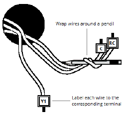
Install Wiring Mount
Remove the wiring mount from the packaging, and use the included wall screws and/or anchors to attach the wiring mount to the wall, making sure the wires run through the center opening. If alternate mounting holes are required, use a wall plate (sold separately).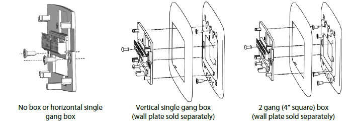
Attach Wiring
Connect the labeled wires to their matching terminals based on the fan coil configuration as follows:
| Configuration | R | C | WY | YA | Gl | Gm | Gh | Ac | Ac | Tp | Tx | Ts | Tc* |
| 2-pipe Heat Only | √ | √ | W | √ | √ | √ | O | O | O | O | O | ||
| 2-pipe Cool Only | √ | √ | Y | √ | √ | √ | O | O | O | O | O | ||
| 2-pipe Heat or Cool –
Manual changeover |
√ | √ | W/Y | √ | √ | √ | O | O | O | O | O | ||
| 2-pipe Heat or Cool –
Seasonal changeover |
√ | √ | W/Y | √ | √ | √ | O | O | √ | O | O | √ | |
| 2-pipe Heat or Cool with Auxiliary Heat | √ | √ | W/Y | A | √ | √ | √ | O | O | √ | O | O | √ |
| 4-pipe Heat / Cool,
Manual or Auto changeover |
√ | √ | W | Y | √ | √ | √ | O | O | O | O | O |
External Antenna
Depending on the installation location, an external antenna may be required for proper radio coverage. To attach the antenna (sold separately), remove the antenna connector cover on the controller and attach the external antenna to the connector, making sure the connector is screwed on finger tight. Place the external antenna in a location without large metal enclosures or pipes between the controller and the Wireless Fan Coil Remote.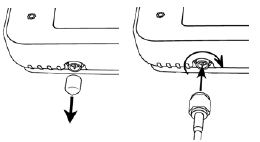
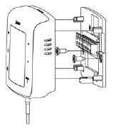
Attach Controller to Wiring Mount
Attach the controller to the wiring mount by aligning the connector pins and the plastic retention posts and pushing the controller onto the wiring mount. Make sure the connector pins are not bent and that the controller is fully seated on the wiring mount
Turn On Power to the Fan Coil System
Turn on the circuit breaker at the breaker panel to power up the fan coil system and thermostat.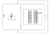
Pair Controller and/or Remote
- After power up, the Wireless Fan Coil Controller will display the pairing screen to join a Smart Home system (see the Smart
- Home pairing guide for directions). After joining, the controller enters Parameter Setup to configure the controller. After configuration, place the controller in Identify Mode, then power up and pair the remote to the system which will then automatically link the two devices.
If not using a Smart Home system, the Wireless Fan Coil - Controller can build its own network. Press SETTINGS ( ) to skip pairing and confirm “build” using
 , and SELECT.
 - Once the network is built, the controller will display the radio channel number being used, then enter Parameter Setup to configure the controller. After configuration, place the controller in Identify Mode and power up the Wireless Fan Coil Remote, which will then automatically link the two devices.

- To enter Parameter Setup immediately and skip the pairing and build processes, press SETTINGS ( ) and decline building a network.
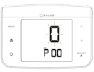
Configuring the Thermostat
In Installer Mode, the buttons have the following function:
| Button | Function |
| SELECT
short press long press (~2s) |
Save displayed value for parameter and,
go to next parameter (wrap around at end back to 0) go to previous parameter (wrap at 0 to end of parameters) |
| A or Y | Up or down selection of value options for parameter |
| SETTINGS | Exit Installer Mode and go to Home screen |
| Parameter | Name | Values (default in bold) | |
| P00 | Thermostat Type | 0 = Non-Programmable (for home automation systems with schedules)
1 = Programmable |
|
| P01 | Fan Coil Type | 0 = 2 Pipe
1 = 4 pipe |
|
| P02 | Heat/Cool Configuration | For 2 Pipe:
0 = Heat Only 1 = Cool Only 2 = Heat or Cool, Manual changeover 3 = Heat or Cool Seasonal changeover (Pipe sensor required) 4 = Heat or Cool with Auxiliary Heat (Pipe sensor required) |
For 4 Pipe: |
| 2 = Heat or Cool Manual changeover
3 = Heat, Cool or Auto changeover 4 = Auto changeover only |
|||
| P03 | Pipe Valve Type | 0 = Normally closed
1 = Normally open |
|
| P12 | External Sensor Type | 0 = External sensor
1 = Zigbee remote sensor |
|
| P13 | Pipe Sensor Type | 0 = Analog input
1 = Normal open, default mode is Heat 2 = Normal open, default mode is Cool 3 = Normal close, default mode is Heat 4 = Normal close, default mode is Cool |
|
Normal Operation
After exiting Installer Mode, the device will go to the Home Screen with the following button functions.
| Button | Function |
| MODE | Select heat/cool/auto mode |
| FAN | Select fan operating mode |
| SETTINGS | Enter/Exit User Settings Mode for the following user accessible settings:
· C/F temperature units selection · Internal/External temperature sensor selection · Setback set point setup (if P16 is not Disable) · 12/24 hour time display mode selection · Set Time (if Standalone or Local mode) · Set Month and Date (if Standalone or Local mode) · Set Year (if Standalone or Local mode) · Enter Program Schedule mode (if P0 = Programmable) · Set temperature offset |
| A or V | Home Screen: Enter Set Point Change mode
Set Point Change: increase or decrease the set point for the selected heat/cool mode |
| SELECT | Home Screen: Select what to display under ambient temperature; time, or set point and humidity.
Set Point Change: Toggle state of permanent hold between ON and OFF |
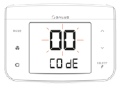
Code Functions
The device can perform additional functions required for certain situations. To access the functions, press the MODE, FAN, and SETTINGS buttons simultaneously until the C0dE screen appears (~2 seconds). Enter the code for the desired function from the table below using the buttons, then press SELECT to perform the function. If confirmation is required (buttons to display y, then SELECT) and is not received within 3 minutes, the device will return to the Home Screen
| Code | Function |
| 00 | Identify Mode: Flashes display and links to Wireless Fan Coil Remote if available. |
| 49 | Parameter Setup: function to set operating parameters. |
|
55 |
Join/Leave Network:
If not part of a network, the device will start the pairing process. If part of a network, the device will ask for confirmation to unpair from the network. If confirmed, the device will leave the network and start the pairing process. |
| 56 | Unpair Remote: If a fan coil remote is paired to the controller, this function unpairs the remote. The device will ask for confirmation to unpair the fan coil remote. |
| 86 | Factory Default: Restores all parameters to factory default values and reboots. The device will ask for confirmation to restore factory defaults. |
Warranty
SALUS North America, Inc. (“Salus”) warrants that for a period of five (5) years (“Warranty Period”) from the date of purchase by the consumer (“Customer”), this device, excluding batteries (“Product”), shall be free of defects in materials and workmanship under normal use and service in accordance with all supplied instructions. During the warranty period, Salus shall, at its option, repair or replace any defective Products, at no charge for the device. Any replacement and/or repaired devices are warranted for the remainder of the original Warranty Period or ninety (90) days, whichever is longer. This warranty does not cover removal or reinstallation costs. This warranty does not apply to any Product (i) which has been modified, repaired, or altered, except by Salus or an authorized Salus representative, (ii) which has not been maintained in accordance with any handling or operating instructions supplied by Salus, or (iii) which has been subjected to unusual physical or electrical stress, misuses, abuse, negligence or accidents. This warranty is the only express warranty Salus makes for the Product. Any implied warranties, including warranties of merchantability or fitness for a particular purpose, are limited to the Warranty Period or the shortest period allowed by law.
SALUS SHALL NOT BE LIABLE FOR ANY LOSS OR DAMAGE OF ANY KIND, INCLUDING ANY SPECIAL, INCIDENTAL OR CONSEQUENTIAL DAMAGES RESULTING, DIRECTLY OR INDIRECTLY, FROM ANY BREACH OF ANY WARRANTY, EXPRESS OR IMPLIED, OR ANY OTHER FAILURE OF THIS PRODUCT.
Some states and provinces do not allow the exclusion or limitation of incidental or consequential damages, or limitation on the duration of implied warranties of merchantability or fitness, so these exclusions or
limitations may not apply to you. No oral or written information or advice given by Salus or a Salus- authorized representative shall modify or extend this warranty. If any term is held to be illegal or unenforceable, the legality or enforceability of the remaining terms shall not be affected or impaired. Customer’s sole and exclusive remedy under this limited warranty is product repair or replacement as provided herein. If a Product under warranty is defective, the Customer may:
- Contact the party (“Seller”) from which the Customer purchased the Product to obtain an equivalent replacement product after the Seller has determined that the Product is defective and the Customer is eligible for a replacement, or
- Contact Salus Service at [email protected], to determine whether the device qualifies for a replacement.
- If a replacement is warranted and is shipped prior to the return of the device under warranty, a credit card is required and a hold may be placed on the Customer’s credit card for the value of the replacement until the returned device is verified as eligible for replacement, in which case, the Customer’s credit card will not be charged.
This warranty gives you specific legal rights, and you may also have other rights that vary from jurisdiction to jurisdiction. If you have any questions regarding this warranty, please write Salus at:
- SALUS North America, Inc.
- 850 Main Street
- Redwood City, CA 94063
FCC
This device complies with Part 15 of the FCC Rules. Operation is subject to the following two conditions:
- this device may not cause harmful interference, and
- this device must accept any interference received, including interference that may cause undesired operation. Changes or modifications to this unit not expressly approved by the party responsible for compliance could void the user’s authority to operate the equipment.
NOTE: This equipment has been tested and found to comply with the limits for a Class B digital device, pursuant to Part 15 of the FCC Rules. These limits are designed to provide reasonable protection against harmful interference in a residential installation. This equipment generates, uses and can radiate radio frequency energy, and if not installed and used in accordance with the instructions, may cause harmful interference to radio communications. However, there is no guarantee that interference will not occur in a particular installation. If this equipment does cause harmful interference to radio or television reception, which can be determined by turning the equipment off and on, the user is encouraged to try to correct the interference by one or more of the following measures:
- Reorient or relocate the receiving antenna.
- Increase the separation between the equipment and receiver.
- Connect the equipment into an outlet on a circuit different from that to which the receiver is connected.
- Consult the dealer or an experienced radio/TV technician for help.
FCC AND INDUSTRY CANADA
RF Radiation Exposure statement: This equipment complies with FCC and Industry Canada RF radiation exposure limits set forth for an uncontrolled environment. This equipment should be installed and operated with a minimum distance of 20 centimeters between the antenna and all persons.
INDUSTRY CANADA
This device complies with Industry Canada licence-exempt RSS standard(s). Operation is subject to the following two conditions:
- this device may not cause interference, and
- this device must accept any interference, including interference that may cause undesired operation of the device.
REFERENCE
DOWNLOAD MANUALS:
SALUS SC102ZB Wireless Fan Coil Thermostat Quick Start Guide
OTHER MANUALS:
SALUS SC102ZB Wireless Fan Coil Thermostat Product Specification Sheet
SALUS SC102ZB Wireless Fan Coil Thermostat Installation and Operation Manual
![]()
SALUS SC102ZB Wireless Fan Coil Thermostat Quick Start Guide
Leave a Reply