
Warmup PB112 Thermostat

INTRODUCTION
The PB112 power base is designed to power a TH11x Series control module.
Refer to the technical specifications for maximum resistive load.
INSTALLATION GUIDELINES
TURN OFF POWER TO THE HEATING SYSTEM AT THE MAIN POWER PANEL TO AVOID ELECTRICAL SHOCK. Installation should be carried out by an electrician.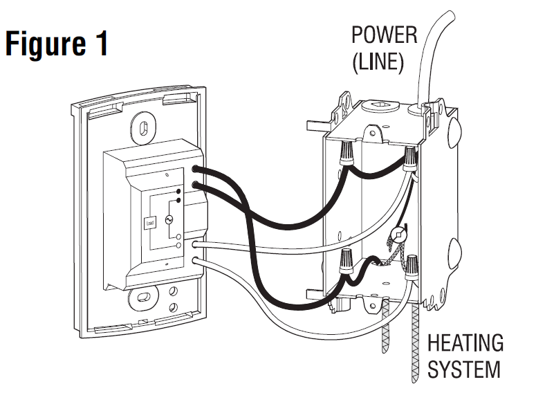
- High-voltage thermostats must be installed onto an electrical box.
- For a new installation, choose a location about 5 ft. above the floor.
- The thermostat must be installed facing the heating system and on an inside wall.
- Avoid locations where there are air drafts (top of staircase, air outlet), dead air spots (behind a door), direct sunlight or concealed chimneys or stove pipes.
Material
- One power base
- Two screws and four solderless connectors for copper wires
NOTE: Special CO/ALR solderless connectors must be used when connecting with aluminum conductors. - One (1) floor sensor and one (1) flat-tip screwdriver (F and AF floor heating models only).
Installation step
- Connect the rear thermostat wires to the floor heating system wires (load) and to the power supply using solderless connectors for copper wires. The floor heating braided shields as well as the power supply copper ground wires must be secured to the ground terminal.
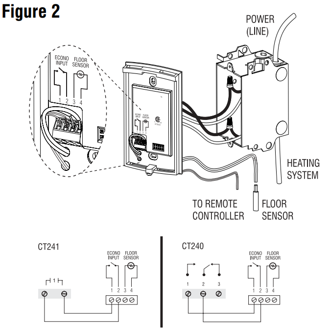
Connection the floor sensor
- Insert the wire into one of the two holes available below the terminal board and connect the wire ends to terminals 3 and 4 (no polarity) as per Figure 2.
- The wire must run on the left side of the cavity located on top of the terminal board, outside the electrical box and follow the wall down to the floor
- The wire must follow the wall down to the floor and must not cross any heating wires nor be directly on or adjacent to a heating wire. For maximum performance, the sensor probe should be centered between the wires in the mat.
Connection the Econo input
- Insert the cable (use an 18 to 22-gauge flexible wire cable) into one of the two holes available below the terminal board.
- Connect the wire ends (no polarity) to terminals 1 and 2 of the power base and to the CT240’s auxiliary output or any output of the CT241.
- The cable must run on the left side of the cavity located on top of the terminal board and outside the electrical box. ” Push the excess wire (except for the sensor & Econo) back into
the electrical box to prevent interference with the thermostat and secure the base to the electrical box using the provided screws. # Configure the switches located on the control module and install the control module onto the base (refer to the user guide).
$ Once completed, return power to the floor heating system.
Technical Specifications
| Model | Supply | Max. Load | Power | Wiring | GFCI |
| 120GA | 120 VAC, 50/60Hz | 15 A | 1800 W | 4w/DP | 5 mA |
| 120GB | 120 VAC, 50/60Hz | 15 A | 1800 W | 4w/DP | 30 mA |
| 120S | 120 VAC, 50/60Hz | 20 A | 2400 W | 4w/SP | |
| 240GA | 240 VAC, 50/60Hz
208 VAC, 50/60Hz |
15 A | 3600 W
3120 W |
4w/DP | 5 mA |
| 240GB | 240 VAC, 50/60Hz
208 VAC, 50/60Hz |
15 A | 3600 W
3120 W |
4w/DP | 30 mA |
| 240D | 240 VAC, 50/60Hz
208 VAC, 50/60Hz |
15 A | 3600 W
3120 W |
4w/DP | |
| 240S | 240 VAC, 50/60Hz | 20 A | 4800 W | 4w/SP | |
| 277S | 277 VAC, 50/60Hz | 15 A | 4155 W | 4w/SP |
a. Wiring type: 4w = 4 wires, DP = Double Pole, SP = Single Pole
Storage: -4°F to 120°F (-20°C to 50°C)
GFCI: GA = 5 mA, GB = 30 mA trip level
Econo input: requires a dry contact
Size (H • W • D): 4.89 x 2.76 x 0.91 in (124 x 70 x 23 mm)
Certifications:
WARMUP ONE (1) YEAR LIMITED WARRANTY
This product is warranted against material defects and workmanship in normal use for a period of one year, from the date of the original purchase from authorized dealers. During this period, Warmup inc. will repair or replace the product with a new or of equivalent quality at the Warmup inc. option, without charge, any product proven defective in normal use.
The warranty does not cover transportation costs. Nor does it cover a product subjected to misuse or accidental damage. This warranty does not cover the cost of installation, removal, or reinstallation.
This limited warranty is in lieu of all other warranties, obligations or liabilities expressed or implied by the company. In no event shall Warmup inc. be liable for consequential or incidental damages resulting from the installation of this product. Some states or provinces do not allow limitations on how long an implied warranty lasts or the exclusion or limitation of incidental or consequential damages, so the above exclusions or limitations may not apply to you. This warranty gives you specific legal rights and you may also have other rights, which vary from state to state.
The defective product and the original sale receipt must be returned to the original dealer or shipped prepaid, insured, and addressed to:
Warmup
1805 Old Alabama Road, Suite 200
Roswell, GA 30076
If you have any questions concerning the installation or programming of this product, please call our technical assistance at 678 323 1434.
Monday to Friday between 8:30 AM and 5:00 PM Eastern time.
REFERENCE:
Download Manual:
Warmup PB112 Thermostat Installation Instruction
![]()
Leave a Reply