
![]()
Vtronix TF65L-001 Digital Room Thermostats
APPLICATION
DR is a serie of Digital Room Thermostats, provides a single stage, temperature control. Table 1 shows all the available models. All models can be provided with 24, 120, 220 Vac.
| Model | Operation | Cooling / Heating | Compressor delay |
| 01 | cool + sweep | Compressor | yes |
| 02 | cool + sweep | Chilled water | no |
| 03 | cool – fan – dry | Compressor | yes |
| 04 | cool – fan – dry | Chilled water | no |
| 05 | cool – fan – dry – heat – auto | Compressor / Heat pump | yes |
| 06 | cool – fan – dry – heat – auto | Compressor / Electric heater | yes, only for cool |
| 07 | cool – fan – dry – heat – auto | Hot / Chilled water | no |
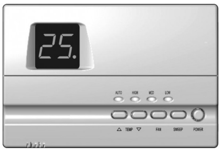
These thermostats are mercury free and require no battery. All set points are kept permanently by non-volatile memory.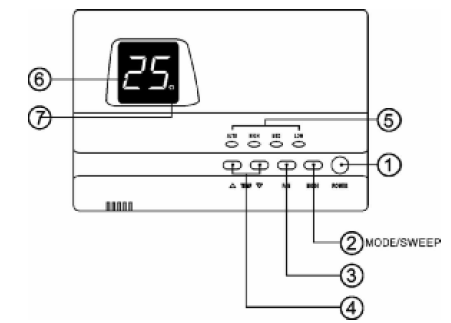 Fig. 1. Digital Room Thermostat.
Model No. Legend
When ordered, put all the information in the Model No. Legend.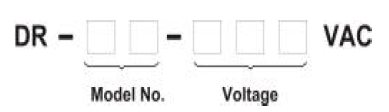
Specification
| POWER SUPPLY | |
| 24 VAC system | 18 – 30 VAC, 50/60 Hz |
| 120 VAC system | 96 – 144 VAC, 50/60 Hz |
| 220 VAC system | 198 – 250 VAC, 50/60 Hz |
| TEMPERATURE : | |
| Temperature accuracy | ± 1 °C |
| Storage temperature | 0 – 70 °C |
| Ambient temperature | 10 – 50 °C |
| Setting temperature range | 18 – 30 °C (64 – 88 °F) |
| HEAT and COOL RELAY : ( P1, P2) | |
| Rating (resistive load) | |
| · Maximum switching capacity | 3 A 277 VAC |
| FAN RELAY: (P3, P4, P5) | |
| Rating (resistive load) | |
| · Maximum switching capacity | 2 A 277 VAC
3 A 125 VAC |
Installation
Read these instructions thoroughly before installing product. Failure to follow these instructions could damage the product or cause a hazardous condition. Check the voltage and current ratings on the product to ensure that it is suitable for your application. Installer must be a trained, experienced service technician. Check product for proper operation after installation.
CAUTION
Damage to heating and cooling system may occur. Disconnect power from the equipment at the main breaker/fuse block while installing the thermostat
Mounting Location
Mount the thermostat approximately 5 ft. (1.5m) above the floor in a location that is free from direct sunlight, heat from appliances, hot or cold air from ducts, concealed pipes and chimneys, and drafts or dead spots behind doors or in corners. Do not mount on exterior wall, if possible. Failure to locate thermostat mounting as indicated will result in poor temperature control
Note: Level thermostat mounting is for appearance only and is not required for proper thermostat operation.
Mount and Wire the Thermostat
- Tighten two appropriately sized screws on the wall or on the 2×4 in. junction box. Keeping 1.50 mm distance from the wall.
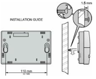
Fig. 2. Tighten screws on the wall - Mount the thermostat on the wall by having it on the screws.
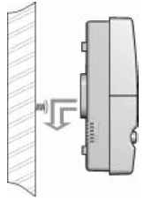
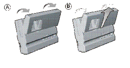
Fig. 3. Mount the thermostat. - Lift and open the cover, pull it up to remove.
See Fig. 4.
- Use cable size 0.5-1 sq. mm connect the wires from heating /cooling equipment to the terminals on the thermostat. See wiring diagram for location of thermostat terminals.
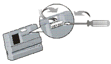
Fig. 5. Connect system wires to thermostat terminals (strip 5/6 inch). - Put the cover back.
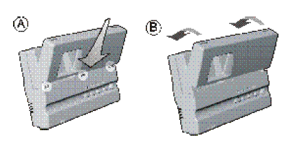
Fig. 6. Put the cover back - Tighten screw to secure the cover.
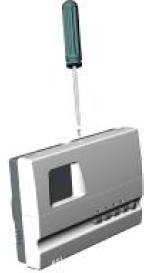
Fig. 7. Tighten the screw.
WIRING DIAGRAM
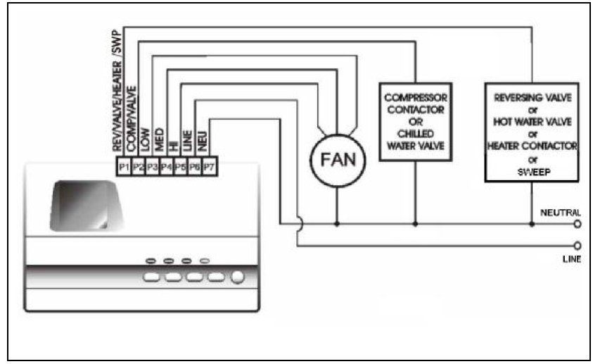 Fig. 8. For 120 or 220 Vac system.
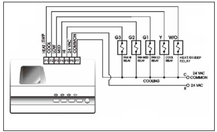
Fig. 9. For 24 Vac system
SET UP
All thermostats are factory set up according to the Model No. Legend listed on the back side of the plastic casing. However it can be alternated by the programming
Set up mode
Press and hold TEMP ![]() and TEMP
and TEMP ![]() and FAN buttons at the same time for 3 seconds, the display will show the existing set up as per Table 2.
and FAN buttons at the same time for 3 seconds, the display will show the existing set up as per Table 2.
| Display | Not blinking | Blinking |
| P1 | Heat /Cool | Cool |
| P2 | Electric heater | No electric heater |
| P3 | °F | °C |
| P4 | No compressor delay | Compressor delay |
| P5 | Sweep | No sweep |
| P6 | Wireless | Wire |
Note: P6 is not used in this serie.
Example 1: the display shows P1 without blinking means the set up is now for Heat / Cool version.
Change the set up
- While in set up mode, press TEMP D or TEMP Ñ button to the required set up program.
- To change the set up to the other version as listed in Table 2, press FAN button.
- Repeat (a) & (b) for the next set up.
- Press MODE or SWEEP button to exit from the setup mode.
OPERATION
Power
Press POWER to turn on/off the air conditioner. When turn on, it will operate according to the last program setting.
Mode/Sweep
For Cool + Sweep version, button is a SWEEP button used to turn on/off the sweep motor. For other versions, this is a MODE button used to select the operation mode.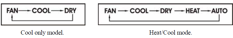
- Cool Mode : LED at will show
 in blinking for 5 seconds
 - Dry Mode : LED at will show
 in blinking for 5 seconds
 - Fan Mode : LED at will show
 in blinking for 5 seconds
 - Heat Mode : LED at will show
- HP blinking for 5 seconds if the Heat Pump version is ordered.
- HE in blinking for 5 seconds if the Electric Heater version is ordered.
- HO in blinking for 5 seconds if the Hot water pipe version is ordered.
- Auto Mode : LED at 6 will show
 in blinking for 5 seconds. The system will automatically switch from Cool to Heat mode or vice versa.
Fan
Press FAN button to select the fan speed in the following sequence.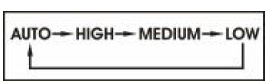
LED at will show the status of the fan.
Auto mode
The speed will be adjusted according to the difference between the room and the setting temperature.
- If the difference is 3°C or more, the fan will run at high speed.
- If the difference is 2°C, the fan will run at medium speed.
- If the difference is 1°C, or lower, the fan will run at low speed.
Temperature setting
Press TEMP D or TEMP Ñ button for setting the temperature in a range of 18 – 30°C or 64 – 88 °F. LED at will show the new setting for 5 seconds.
Compressor delay
In a model with a compressor delay feature, there will be 3-minute time delay before the compressor can restart.
Compressor status
LED at shows the status of the compressor/valve/heater.
Sensor Error Alarm
If the room sensor is open/short-circuit, the controller will stop the compressor or any heating equipment and dot on the 7-segment will blink.
Auto Restart
All the setting parameters are kept in the nonvolatile memory. When there is a power failure and back to normal, the system will resume its operation with the same setting parameters.
REFERENCE:
DOWNLOAD MANUALS:
Vtronix TF65L-001 Digital Room Thermostats INSTALLATION MANUAL
![]()
Vtronix TF65L-001 Digital Room Thermostats INSTALLATION MANUAL
Leave a Reply