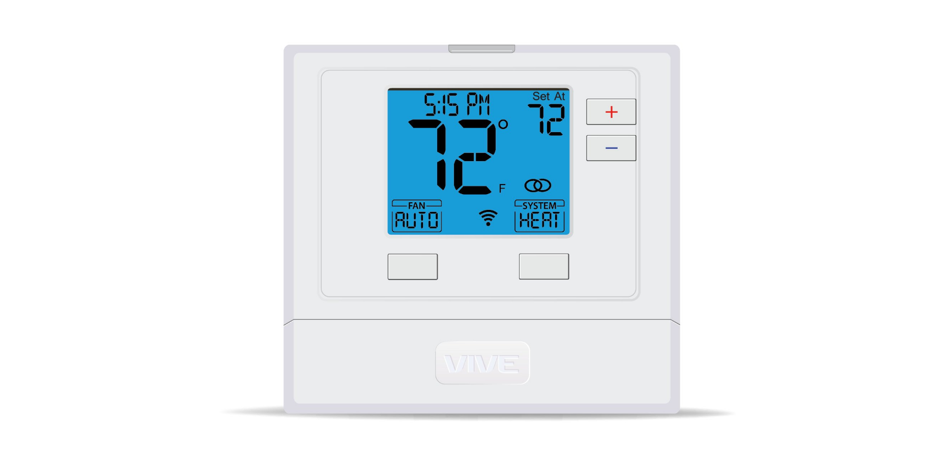
Vive TP-S-721i Smart THERMOSTAT

Vive Comfort
P.O. Box 3377
Springfield, MO 65808-3377
Toll-Free: 888-776-1427
Web: www.vivecomfort.com
Hours of Operation: M-F 9 AM – 6 PM Eastern
Thermostat Application Guide
| Description | |
| Gas or Oil Heat | Yes |
| Electric Furnace | Yes |
| Heat Pump (No Aux. or Emergency Heat) | Yes |
| Heat Pump (With Aux. or Emergency Heat) | Yes |
| Multi-Stage Systems | No |
| Heat Only Systems | Yes |
| Cool Only Systems | Yes |
| Millivolt | No |
Power Type
Hardwire (24V Common Wire)
A trained, experienced technician must install this product
Carefully read these instructions. You could damage this product or cause a hazardous condition if you fail to follow these instructions.
WIFI
- Frequency Range…………2.4 Ghz ISM radio band
- WIFI Module………………………….Supporting 802.11
- B/G/N Standards
Installation Tips
Wall Installation
The thermostat should be installed approximately 4 to 5 feet above the floor. Select an area with average temperature and good air circulation. Pick an installation location that is easy for the user to access. The temperature of the location should be representative of the building.
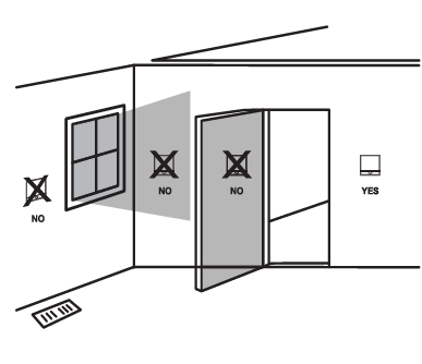
Do not install thermostats in locations
- Close to hot or cold air ducts
- Those are in direct sunlight
- With an outside wall behind the thermostat
- In areas that do not require conditioning
- Where there are dead spots or drafts (in corners or behind doors) Where there might be concealed chimneys or pipes
Removing The Private Label Badge
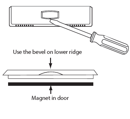
Gently slide a screwdriver into the bottom edge of the badge. Gently turn the screwdriver counterclockwise. The badge is held on by a magnet in the well of the battery door. The badge should pry off easily. DO NOT USE FORCE. All of our thermostats use the same universal magnetic badge. Visit the company website to learn more about our free private label program.
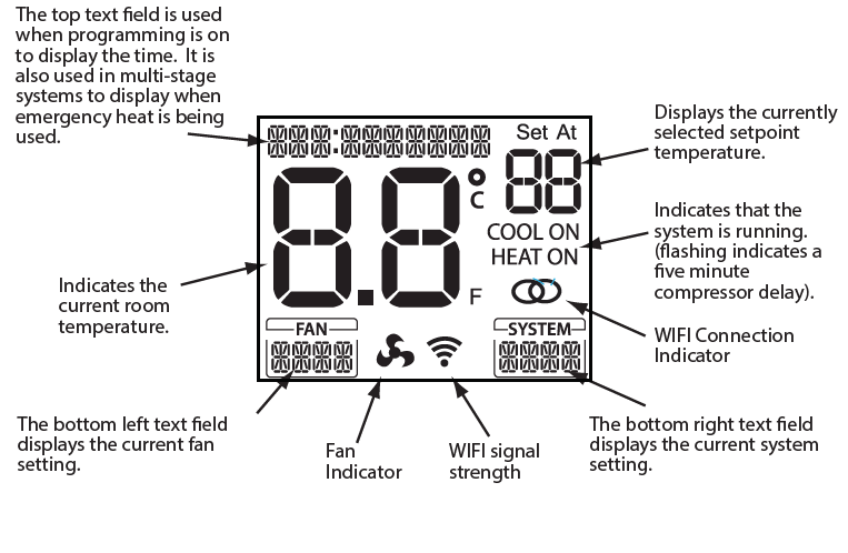
Thermostat Quick Reference
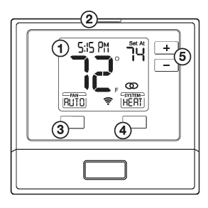
- LCD
- Glow in the dark light button
- Fan button
- System button
- Temperature setpoint buttons
Subbase Installation
- Horizontal Mount
For horizontal mount put one screw on the left and one screw on the right.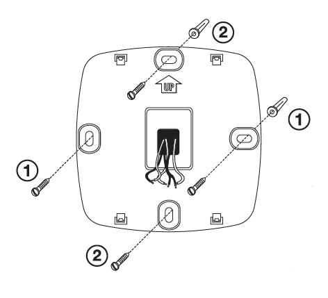
- Vertical Mount
For vertical mount put one screw on the top and one screw on the bottom.
Electrical Hazard
Failure to disconnect the power before beginning to install this product can cause electrical shock or equipment damage.
NOTE: To ensure a solid fit between the thermostat and subbase:
- Mount subbase on a flat wall.
- Use provided screws.
- Ensure drywall anchors are flush with wall.
- Push wires into wall.
Mercury Notice
All of our products are mercury free. However, if the product you are replacing contains mercury, dispose of it properly. Your local waste management authority can give you instructions on recycling and proper disposal.
Mount Thermostat
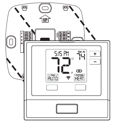
Align the 4 tabs on the subbase with corresponding slots on the back of the thermostat, then push gently until the thermostat snaps in place.
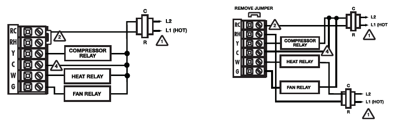
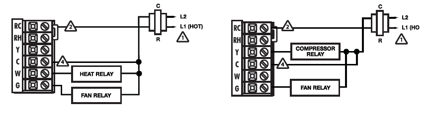
Wiring
- Power Supply
- Factory-installed jumper,remove only when installing on 2-transformer system.
- Use either O or B terminals for changeover valve.
- A 24 VAC 500mA common connection is required with this thermostat.
Typical 1H/1C system: 1 transformer Typical 1H/1C system: 2 transformers
Typical 1H/1C heat pump system Typical heat only systems w/o fan
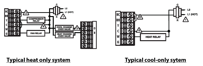
Typical heat only system Typical cool-only sytem
Replacement Thermostat Wiring
- If you are replacing a thermostat, make note of the terminal connections on the thermostat that is being replaced. In some cases the wiring connections will not be color coded. For example, the green wire may not be connected to the G terminal.
- Loosen the terminal block screws. Insert wires then retighten terminal block screws.
- Place nonflammable insulation into wall opening to prevent drafts.
- This thermostat requires a 24V common wire to the C terminal.
Caution
Electrical Hazard Failure to disconnect the power before beginning to install this product can cause electrical shock or equipment damage.
Warning
All components of the control system and the thermostat installation must conform to Class II circuits per the NEC Code.
Installation Tip Max Torque = 6in-lbs.
Do not overtighten terminal block screws, as this can damage the terminal block. A damaged terminal block can keep the thermostat from fitting on the subbase correctly or cause system operation issues.
Wiring Chart
For all systems, the following terminals are wired according to whether you have a single or dual transformer system as shown:
| RH RC | C | G | ||
| SINGLE TRANSFORMER
SYSTEM |
24 VAC HOT JUMPER SHOULD REMAIN
INSTALLED |
24 VAC Common 500mA |
Blower / Fan |
|
| DUAL TRANSFORMER
SYSTEM |
24 VAC-Heat
*REMOVE PROVIDED JUMPER |
24 VAC-Cool
*REMOVE PROVIDED JUMPER |
24 VAC Common 500mA
*FROM COOL TRANSFORMER |
Blower / Fan |
FAILURE TO REMOVE PROVIDED JUMPER ON DUAL TRANSFORMER INSTALLATIONS COULD CAUSE SEVERE DAMAGE TO HVAC SYSTEMS
| O Terminal | Heat pump changeover valve– Energized during cooling |
| B Terminal | Heat pump changeover valve– Energized during heating |
Note: Devices such as a float switch that mechanically break circuits should be installed so that they break the control wire (Y) not the power (R). Interrupting the power circuit will shut off power to the thermostat completely and not allow it to operate.If using in Heat Pump without Auxiliary or Emergency heat application, please see wiring diagram on previous page.
To enter tech setup
- Press and hold the + and – buttons for 3 seconds.
- Press and hold the TECH button.
- Configure the installer options as desired using the table below. Use the + or – buttons to change settings and the PREV and NEXT buttons to move from one step to another.
- To exit tech setup: press and hold the + and – buttons for 3 seconds, or wait 20 seconds.
| Tech Setup Steps | LCD Will Show | Adjustment Options | Default | |
| Room Temperature Calibration | This feature allows the installer to change the calibration of the room temperature display. For example, if the thermostat reads 70 degrees and you would like it to read 72 then select +2. | CALIBRATE
0 |
You can adjust the room temperature display to read 4˚above or below the factory calibrated reading. | O |
| Compressor Short Cycle Delay | The compressor short cycle delay protects the compressor from “short cycling”. This feature will not allow the compressor to be turned on for 5 minutes after it was last turned off. | COMP DELAY
0N |
Selecting “ON” will not allow the compressor to be turned on for 5 minutes after the last time the compressor was switched off. Select “OFF” to remove this delay. | ON |
|
Cooling Swing |
The swing setting often called “cycle rate”, “differential”, or “anticipation” is adjustable. A smaller swing setting will cause more frequent cycles and a larger swing setting will cause fewer cycles. | COOL SWING | The cooling swing setting is adjustable from 0.2˚ to 2˚. A swing setting of 0.5˚will begin cooling at approximately 0.5˚ above the setpoint and stop approximately 0.5˚ below the setpoint. |
0.5 ˚F |
|
Heating Swing |
The swing setting often called “cycle rate”, “differential”, or “anticipation” is adjustable. A smaller swing setting will cause more frequent cycles and a larger swing setting will cause fewer cycles. | HEAT SWING | The heating swing setting is adjustable from 0.2˚ to 2˚. A swing setting of 0.5˚will begin heating at approximately 0.5˚ below the setpoint and begin approximately 0.5˚ above the setpoint. |
0.5 ˚F |
|
Heat Pump |
When set to ON this thermostat will operate a heat pump system (default). If set to OFF this thermostat will operate a conventional system, and the next tech step will not appear. | HEAT PUMP | ON – Configured to operate heat pump system.
OFF – Configured to operate conventional system See page 5 for terminal designations. |
ON |
| Emergency Heat
(Only displayed if Heat Pump is set to ON.) |
When set to ON, this setting will enable Emergency Heat in Heat Pump mode. | HEAT PUMP | ON – Enables Emergency Heat
OFF – Disables Emergency Heat. |
ON |
Swing Setting Tip
Temperature swing, sometimes called differential or cycle rate, can be customized for this individual application. For most applications choose a swing setting that is as wide as possible without making the occupants uncomfortable.
| Tech Setup Steps | LCD Will Show | Adjustment Options | Default | |
| Emergency Heat Stages
(Only displayed if Emergency Heat is set to ON) |
This feature controls the number of stages in Emergency Heat mode. It only appears if the Technician Setup Step for HEAT PUMP is ON. | E HEAT STG
1 |
Use the or key to select 1-stage or 2-stage operation. | 1 |
| Dual Fuel Auxiliary for Heat Pump
(Only displayed if Heat Pump is set to ON) |
For Dual Fuel applications (Gas/ Fossil fuel Auxiliary Heat), turn this setting ON to LOCKOUT the Heat Pump (Y) when Auxiliary Heat (W2) is on. If desired- This can also be used with Electric Auxiliary. | DUAL FUEL
OF |
OFF will allow Y(1st stage of Heat) and W2 (Aux Heat) to run together if called for.
ON Will de-energize Y terminal 45 seconds after a call for Auxiliary Heat (W2). |
OFF |
|
Satisfy Setpoint |
This feature allows the thermostat to keep multiple stages of heat energized until setpoint is satisfied. | SATISFY SP
OF |
Use the or key to turn ON or OFF. | OFF |
|
Staging Delay |
This feature allows a delay to occur when a second stage is needed. This allows the previous stage extra time to satisfy setpoint. | STG DELAY
OF |
Use the or key to select OFF, 5, 10, 15, 30, 45,
60, or 90 minutes. |
OFF |
|
Minimum Compressor On Time |
This feature allows the installer to select the minimum run time for the compressor. For
example, a setting of 4 will force the compressor to run for at least 4 minutes every time the compressor turns on, regardless of the room temperature. |
MIN COMP
OF |
You can set the minimum compressor run time to “OFF”, “3”, “4”, or “5” minutes.
If 3, 4 or 5 is selected, the compressor will run for at least the selected time before turning off. Use the and buttons to change the setting. |
OFF |
| Heating Setpoint Limit | This feature allows you to set a maximum heat setpoint value. The setpoint temperature cannot be raised above this value. | HEAT LIMIT
90 |
Use the + and – buttons to select the maximum heat setpoint. |
90 |
|
Cooling Setpoint Limit |
This feature allows you to set a minimum cool setpoint value. The setpoint temperature cannot be raised above this value. | COOL LIMIT
44 |
Use the + and – buttons to select the minimum cool setpoint. |
44 |
| Tech Setup Steps | LCD Will Show | Adjustment Options | Default | ||
|
˚F or ˚C
Display Light |
This feature allows you to display temperature in either Fahrenheit or Celsius.
The display light can be configured to operate 3 different ways. To come on only when the Light Key is pressed, when Any Key is pressed, or stay on ALL of the time. |
F OR C
F DISP LIGHT OF |
˚F for Fahrenheit
AUTO “AU” – Any key ON ON – light always on OFF – light on when any button is pressed |
˚F
OFF |
|
|
Programmable |
You can configure this thermostat to accept a programmed schedule from the mobile App. | PROGRAMABLE
OF |
Select “OF” to configure the thermostat for NON-Program- mable. (Time of day will NOT appear on display).
Select “ON” to configure the thermostat for programmable operation, from the app. |
OFF |
|
WIFI Setup
Operation of the FAN & SYSTEM button when connected to WIFI and running a programmable schedule from the app: When the set at temperature is changed while an app schedule is running, the thermostat will enter a temporary hold, and the Fan and System buttons change to RUN and HOLD for 5 seconds. If you wish to enter PERMANENT HOLD press the HOLD button at this time. If you don’t press the HOLD button within the 5 seconds, it will remain in temporary hold for 4 hours. When connected to WIFI you may also have the ability to turn programming ON or OFF by pressing and holding the FAN button for 3 seconds, while the FAN BOX appears.
- These WIFI Technician steps/ options are intended for information and trouble-shooting. They are not used for installation or initial setup.
- Follow these steps to enter the WIFI-technical information menu.
- The only normal function you would use this step for would be to RESET WIFI provisioning. For example: If you replaced your home
- WIFI router and need to connect via a different network.
- Follow these steps to enter the WIFI-technical information menu.
- Press and hold the + and – buttons together for 3 seconds.
- Press the WIFI button on the lower right.
- The top of the display will show: “WIFI IDLE” if NOT connected to WIFI and “CONNECTED” if connected.
- If the NEXT button is pressed, top of display will show: The firmware and software versions that are installed on the thermostat.
- If the NEXT button is pressed again, the top of the display will show:
The SSID # of the thermostat. if NEXT is pressed again, you will return to step 3.- Go through steps 1 and 2 from the WIFI menu on the left.
- Press and hold the TECH button on the lower left for 3 seconds.
- The top of display will show: “RESET WIFI”
- Press and hold the YES button on the lower left. After a 5 second countdown, the thermostat will reset. Or press NO to exit
Specifications
- The display range of temperature ………………………… 41˚F to 95˚F (5˚C to 35˚C)
- The control range of temperature…………………………. 44˚F to 90˚F (7˚C to 32˚C)
- Load rating………………………………………………………………….1 amp per terminal, 1.5 amp
- maximum all terminals combined
- Display Accuracy……………………………………………………….. ± 1˚F
- Swing (cycle rate or differential) ……………………………. The heating is adjustable from 0.2˚ to 2.0˚
- Cooling is adjustable from 0.2˚ to 2.0˚
- Power source ……………………………………………………………..18 to 30 VAC, NEC Class II, 50/60 Hz
- for hardwire. 500 mA
- Operating ambient ………………………………………………….. 32˚F to +105˚F (0˚C to +41˚C)
- Operating humidity …………………………………………………. 90% non-condensing maximum
- Dimensions of thermostat ………………………………………. 4.7”W x 4.4”H x 0.8”D
REFERENCE:
Download Manual:
Vive TP-S-721i Smart THERMOSTAT User Manual
https://device.report/energystar/2404154
Vive TP-S-721i Smart THERMOSTAT – Energy Star Certification
Download Other Manuals: Vive TP-S-701i Thermostat Operation Manual
Leave a Reply