
VIVE Comfort TP-N-501M Thermostat

Wall Locations
The thermostat should be installed approximately 4 to 5 feet above the floor. Select an area with average temperature and good air circulation
Do not install thermostat in locations:
- Close to hot or cold air ducts
- That are in direct sunlight
- With an outside wall behind the thermostat
- In areas that do not require conditioning
- Where there are dead spots or drafts (in corners or behind doors)
- Where there might be concealed chimneys or pipes
Thermostat Application Guide
- For Use On
- Most 24V Heating and A/C Systems Gas or Oil Heat
- Electric Furnace
- Heat Pump With NO Auxiliary Heat Heat Only Systems
- Cool Only Systems
- Millivolt Systems
- NOT For Use On
- Multi Stage Systems
- Line Voltage Systems Compressors With No Built In Delay 3 Wire Hydronic Systems
Power Type
- Battery Power
- Hardwire (Common Wire)
- Hardwire (Common Wire) with
- Battery Backup
Private Label Badge
Subbase Installation
- Horizontal Mount
- Vertical Mount

Removing The Private Label Badge
Gently slide a screwdriver into the bottom edge of the badge. Gently turn the screwdriver counter clockwise. The badge is held on by a magnet in the front plastic. The badge should pry off easily. DO NOT USE FORCE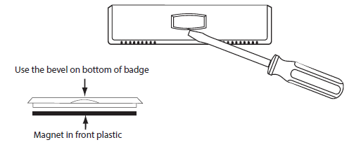
About The Badge
All of our thermostats use the same universal magnetic badge. Visit the company website to learn more about our free private label program.
Wiring
- If you are replacing a thermostat, make note of the terminal connections on the thermostat that is being replaced.
- In some cases the wiring connections will not be color coded. For example, the green wire may not be connected to the G terminal.
- Loosen the terminal block screws.
- Insert wires then retighten the terminal block screws.
- Place nonflammable insulation into the wall opening to prevent drafts.
Terminal Designations
- O Heat pump changeover valve energized in cooling
- B Heat pump changeover valve energized in heating
- W Heat relay
- RH Transformer power for heating
- RC Transformer power for cooling
- G Fan relay
- Y Compressor relay
Wiring Tips
- RH & RC Terminals
- For single transformer systems, leave the jumper wire in place between the RH and RC. Remove jumper wire for two transformer systems.
- Wire Specifications
- Use 18-22 gauge thermostat wire.
- Heat Pump Systems
- If wiring to a heat pump, use a small piece of wire (not supplied) to connect terminals W and Y.
Wiring Diagrams
Removing & Replacing The Front Cover
Remove Front Cover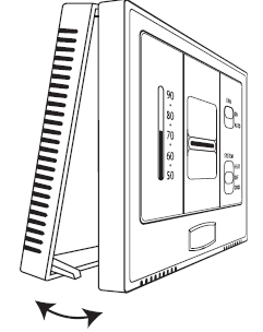 Faceplate Application Options
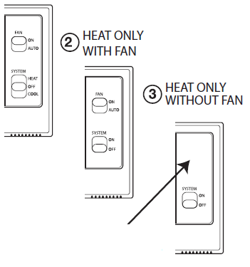
For HEAT ONLY without FAN:
-
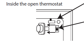
- Put the GAS/ELEC switch in the GAS position (Left).
- Put the FAN in the AUTO (down) posi-tion. Then pull the FAN button off the switch. The faceplate will then cover and hide the FAN switch.
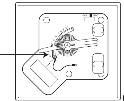
Anticipator Setting
Heating Anticipator Setting
Set the adjustable heat anticipator to match the current draw of the system in heat mode. With the thermostat wired to the HVAC system and mounted on the wall, remove the thermostat from the subbase. Place ammeter probes on the RH and W terminals. After one minute of heating runtime, the ammeter will show a steady current draw value. This current draw value in milliamps on the ammeter is the same value that the anticipator needs to be set to for best results. Set anticipator dial to match the steady ammeter reading in milliamps.
Anticipator Settings
- Higher anticipator values will allow longer running heat cycles.
- Lower anticipator values will allow shorter running heat cycles.
- Note: For millivolt systems, set anticipator to its lowest setting.
Replacing Application Faceplates
To remove faceplate from the front cover, press the back of the faceplate near the edge of the front cover until the faceplate snaps out of its place. Replace different faceplate by placing the new faceplate in open space on the front of the front cover. Press the edge of the faceplate into the front of the front cover until it snaps into place.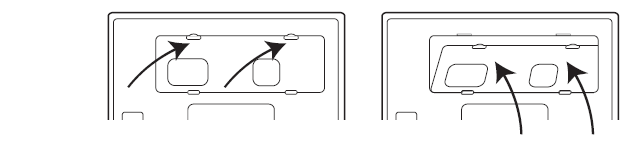
REFERENCE
DOWNLOAD MANUAL
VIVE Comfort TP-N-501M Thermostat INSTALLATION MANUAL
![]()
Leave a Reply