
VIMAR 02972 KNX Wheel Thermostat
For all the details about the Well-contact Plus system, refer to the installer manual that can be downloaded from the Software Product Software Well-contact Plus section of the website: www.vimar.com.
Thermostat
General characteristics and functions
Electronic dial thermostat for room temperature control (heating and air conditioning), KNX standard home automation system, class I temperature control device (contribution 1%) in ON/OFF mode, class IV (contribution 2%) in PID mode, can be interfaced with an actuator with KNX propor-tional analogue outputs to implement a class V modulating room thermostat (contribution 3%), 1 input for electronic temperature sensor 20432, 19432 or 14432 or wired tempe-rature sensor 02965.1, 1 programmable digital input, white/grey LED backlighting – 2 modules. To be completed with Eikon, Arké, Plana cover plates. For Idea, can be installed using the dedicated mounting frame 16723.
General characteristics
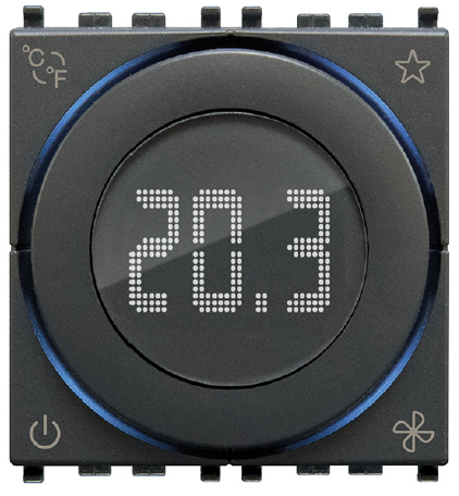
term The thermostat is fitted with a front dial to adjust the setpoint (between 4°C and 40°C) and a central white LED backlit display to show the measured temperature, and show the setpoint only when the dial is being used. The circular ring around the display, with RGB backlighting, displays all the thermostat statuses. The device is fitted with 4 front buttons to be used for settings. The thermostat, physical address, parameters, and its operation, etc. are configured via the ETS software.
Front view
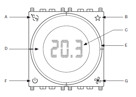
| A | • Short press = degrees Celsius/Fahrenheit selection |
|
B |
Configurable functions:
– send scene (only one scene) – light ON/OFF button – show external temperature from connected temperature sensor – choice season (Heating/Cooling) |
|
C |
Display
• off = thermostat off; on = thermostat on • °C = degrees Celsius; °F = degrees Fahrenheit • H = heating; C = air conditioning |
|
D |
Dial
• Rotation P = set point increase (0.1 °C – 0.2 °F) • Rotation Q = set point decrease (0.1 °C – 0.2 °F) |
| E | Illuminating circular ring |
|
F |
• Power on and off.
At power on or off, the thermostat starts in the last operating mode associated with it |
| G | • Short press = fan coil speed adjustment (0-1-2-3 or Proportional/Automatic) |
Circular ring
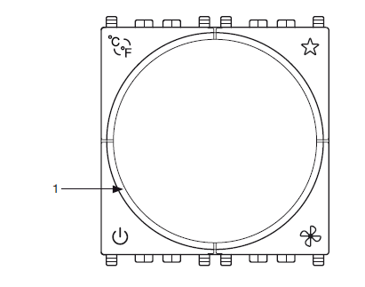
| All lit amber* = thermostat in heating mode and relay active | |
| All lit blue** = thermostat in air conditioning mode and relay active | |
| All flashing red = thermostat locked, alarm state | |
|
1 |
• Lit amber* = thermostat in heating mode and relay not active
• Lit blue** = thermostat air conditioning mode and relay not active |
Amber with automatic color; of the selected color if monochrome.
Blue with automatic color; of the selected color if monochrome.
Default behavior
Thermostat OFF Protection mode
Thermostat ON Comfort mode
Behavior after bus power on/off
Bus power off:
Bus power on the status will be set based on the setting of the parameters and the corresponding telegrams sent over the Bus.
Behavior after reset
As for Bus power-on.
N.B. The thermostat saves the comfort and standby setpoints set manually by the user; if you wish to reset them, set the ETS parameter “Reset Setpoint Shift in Economy Mode=YES”. When switched to “Economy” mode, the thermostat will reset the STBY and CNF values.
General characteristics and functions
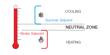
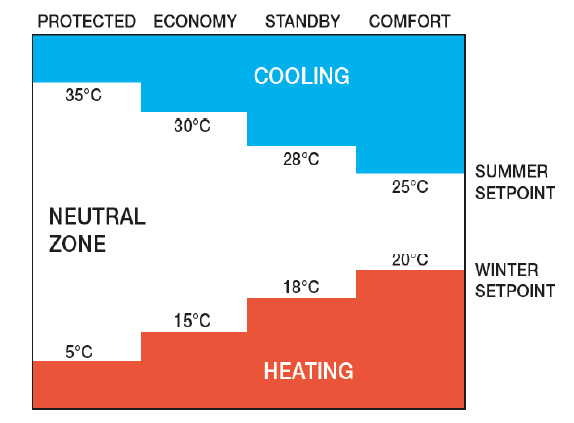
Neutral zone
The “Neutral Zone” is an operating mode of the thermostat (only for 4-pipe systems) in which the device keeps the temperature within a temperature range preset by the Winter Setpoint and Summer Setpoint (basically, there is no longer the usual Summer/Winter mode). If the measured temperature is below the Winter Setpoint, the thermostat switches on the heating valve and heats the room until the temperature exceeds the set value (e.g. 20°C for Comfort mode or 18°C for Standby mode). If the measured temperature exceeds the Summer Setpoint then the thermostat switches on the cooling valve and keeps it on until the temperature falls below the set Summer Setpoint value. Within the Neutral Zone, the thermostat does not switch on any valves and the temperature can vary freely; this zone is therefore nothing more than the difference between the Summer and Winter Setpoints when the room temperature is between the winter setpoint and the summer one. To avoid excessive temperature fluctuations, set a limited range (≤ 2°C) as shown in the figure below.
Setpoint displayed in Neutral Zone operation
When the thermostat is working in the neutral zone, the setpoint used for the adjustment is always the Current Setpoint, namely the one relating to the last heating/cooling mode that came into operation; the value displayed is instead a new setpoint named “Neutral Zone Setpoint”, which is the average value between the current summer and winter setpoints. Changing the temperature of the “Neutral Zone Setpoint” (with the “+” and “-” buttons on the thermostat) will also cause a change to the value of the “Shift Setpoint” resulting in a shift of the two current summer/winter setpoint values; the room temperature will therefore not become the one set by the guest but that of the summer/winter setpoint which at that moment is closest to the value of the current temperature in the room. Between the two summer/winter setpoints, there is the neutral zone in which the system is not activated.
Mid Season
This function is available from the supervisor only for systems configured with primary and secondary output; when active, it exchanges the 2 main and secondary outputs (and the related parameters too). It is recommended for making minor adjustments (such as +/-2 °C) during mid-season periods where it may be more convenient to operate only the secondary circuit (for instance Split).
Configuration
The KNX 02972 thermostat is configured in Neutral Zone mode if the following object is NOT connected: “Enable A: Summer – Winter – control” or “Enable B: Summer – Winter – control”. The thermostat can operate in Neutral Zone IF:
- The system has 4 pipes
- Winter Comfort Setpoint < Summer Comfort Setpoint
- Winter Standby Setpoint < Summer Standby Setpoint
- Winter Economy Setpoint < Summer Economy Setpoint
- Antifreeze < Too Hot
If these conditions are not satisfied, you can still commission the thermostat; if there is an error while starting up, the device will remain in “Protected” mode and an error message will be displayed.
Types of errors at the time of configuration
| Error No. | Description |
| E1 | Selected 2-pipe system instead of 4-pipe system |
| E2 | Winter Comfort Setpoint ≥ Summer Comfort Setpoint |
| E3 | Winter Standby Setpoint ≥ Summer Standby Setpoint |
| E4 | Winter Economy Setpoint ≥ Summer Economy Setpoint |
| E5 | Antifreeze ≥ Too Hot |
N.B. Errors E2, E3, E4, and E5 may also be displayed if the thermostat is programmed in “4-pipe system” mode without the neutral zone according to the type of Setpoint shown in the table
List of existing communication objects and standard settings
| No. | ETS name | Function | Description | Type | Flag 1 | Priority | |||||||
| C | R | W | T | U | I | ||||||||
|
1 |
Internal sensor |
Internal probe temperature |
To see the temperature read by the thermostat sensor (to see the temperatures measured by thermostats A/B with Well-Contact Suite software, objects nos. 10/11 should be used) |
2 byte |
C |
R |
– |
T |
– |
– |
Low |
||
|
2 |
External sensor |
External NTC probe temper- ature |
To see the temperature read by the wired NTC probe connected to the thermostat (to see the temperatures measured by thermostats A/B with Well-Contact Suite software, objects nos. 10/11 should be used) |
2 byte |
C |
R |
– |
T |
– |
– |
Low |
||
|
3 |
External Temperature 1 |
KNX probe temperature on bus |
To see the temperature read by a KNX sensor con- nected to the bus (to see the temperatures measured by thermostats A/B with Well-Contact Suite software, objects nos. 10/11 should be used) |
2 byte |
C |
– |
W |
– |
U |
– |
Low |
||
|
4 |
External Temperature 2 |
KNX probe temperature on bus |
To see the temperature read by a KNX sensor con- nected to the bus (to see the temperatures measured by thermostats A/B with Well-Contact Suite software, objects nos. 10/11 should be used) |
2 byte |
C |
– |
W |
– |
U |
– |
Low |
||
|
5 |
External Temperature 3 |
KNX probe temperature on bus |
To see the temperature read by a KNX sensor con- nected to the bus (to see the temperatures measured by thermostats A/B with Well-Contact Suite software, objects nos. 10/11 should be used) |
2 byte |
C |
– |
W |
– |
U |
– |
Low |
||
|
6 |
External Temperature 4 |
KNX probe temperature on bus |
To see the temperature read by a KNX sensor con- nected to the bus (to see the temperatures measured by thermostats A/B with Well-Contact Suite software, objects nos. 10/11 should be used) |
2 byte |
C |
– |
W |
– |
U |
– |
Low |
||
|
7 |
External Temperature 5 |
KNX probe temperature on bus |
To see the temperature read by a KNX sensor con- nected to the bus (to see the temperatures measured by thermostats A/B with Well-Contact Suite software, objects nos. 10/11 should be used) |
2 byte |
C |
– |
W |
– |
U |
– |
Low |
||
|
COMMUNICATION OBJECTS |
|||||||||||||
|
8 |
External Temperature 6 |
KNX probe temperature on bus |
To see the temperature read by a KNX sensor con- nected to the bus (to see the temperatures measured by thermostats A/B with Well-Contact Suite software, objects nos. 10/11 should be used) |
2 byte |
C |
– |
W |
– |
U |
– |
Low |
||
|
9 |
External Temperature 7 |
KNX probe temperature on bus |
To see the temperature read by a KNX sensor con- nected to the bus (to see the temperatures measured by thermostats A/B with Well-Contact Suite software, objects nos. 10/11 should be used) |
2 byte |
C |
– |
W |
– |
U |
– |
Low |
||
|
10 |
External Temperature 8 |
KNX probe temperature on bus |
To see the temperature read by a KNX sensor con- nected to the bus (to see the temperatures measured by thermostats A/B with Well-Contact Suite software, objects nos. 10/11 should be used) |
2 byte |
C |
– |
W |
– |
U |
– |
Low |
||
|
11 |
Current Temperature |
A: Temperature |
To see the current temperature associated with ther- mostat-A (weighted average of the various associated probes): this object is used with Well-Contact Suite software to see the temperature measured by thermo- stat A |
2 byte |
C |
R |
– |
T |
– |
– |
Low |
||
|
12 |
Current Temperature |
B: Temperature |
To see the current temperature associated with ther- mostat-B (weighted average of the various associated probes): this object is used with Well-Contact Suite software to see the temperature measured by thermo- stat B |
2 byte |
C |
R |
– |
T |
– |
– |
Low |
||
| THERMOSTAT A: | |||||||||||||
|
13 |
Comfort |
A: Mode – control |
To select COMFORT operating mode by sending a 1 bit or to set the thermostat to STANDBY by sending a 0 bit |
1 bit |
C |
– |
W |
– |
U |
– |
Low |
||
| 14 | Energy Saving | A: Mode – control | To select ECONOMY operating mode by sending a 1 bit (a 0 bit is ignored) | 1 bit | C | – | W | – | U | – | Low | ||
|
15 |
Protected |
A: Mode – control |
To select OFF-ANTIFREEZE operating mode (or Too Hot in the case of air conditioning) by sending a 1 bit. |
1 bit |
C |
– |
W |
– |
U |
– |
Low |
||
| 16 | Off | A: Mode – control | To select OFF operating mode by sending a 1 bit (a 0 bit is ignored) | 1 bit | C | R | W | – | U | – | Low | ||
|
17 |
Thermostat Mode |
A: Mode – control |
To select operating mode by sending a Byte (1 = Comfort, 2 = StandBy, 3 = Economy, 4 = Protection). If you use supervision with Well Contact Suite this object must be associated with a group. |
1 byte |
C |
– |
W |
– |
U |
– |
Low |
||
|
18 |
Thermostat Mode |
A: Mode – status |
To read the set operating mode by sending a Byte (1 = Comfort, 2 = StandBy, 3 = Economy, 4 = Protection). If you use supervision with Well Contact Suite this object must be associated with a group. |
1 byte |
C |
R |
– |
T |
– |
– |
Low |
||
| No. | ETS name | Function | Description | Type | Flag 1 | Priority | |||||
| C | R | W | T | U | I | ||||||
| 19 | Status | A: Mid season – status | To read the seasonal mode set on the thermostat (0 = MS Not Active, 1 = MS Active) | 1 bit | C | R | – | T | – | – | Low |
| 20 | Enable | A: Mid season – control | To select the seasonal mode set on the thermostat (0 = MS Not active, 1 = MS Active) | 1 bit | C | – | W | – | U | – | Low |
| 21 | Status | A: Summer – Winter – status | To read the seasonal mode set on the thermostat (0 = Summer, 1 = Winter) | 1 bit | C | R | – | T | – | – | Low |
|
22 |
Enable |
A: Summer – Winter – control |
To set the seasonal mode on the thermostat
(1 = Winter, 0 = Summer). If it is NOT associated with a group then thermostat A will function in Neutral Zone mode. |
1 bit |
C |
– |
W |
– |
U |
– |
Low |
| 23 | Thermostat Off | A: OFF communication – bus
– control |
This function is useful in the event of faults on the heat- ing system to disable the valves with a 1 bit. | 1 bit | C | – | W | – | U | – | Low |
|
24 |
Dewpoint |
A: Thermostat – control |
If a 1 bit is sent to this object, the thermostat turn OFF and stop the air conditioner (this works only in air condi- tioning mode and serves for example to avoid conden- sation on the floor) – Note: The thermostat requires a cyclical send to this object, with a time that can be set in the parameter “Dewpoint Supervision Time” |
1 bit |
C |
– |
W |
– |
U |
– |
Low |
| 25 | NOT USED | ||||||||||
|
26 |
Current Setpoint |
A: Setpoint – status |
To read the temperature setpoint set on the thermostat. If you want Well-contact Suite to know the setpoint cur- rently set on the thermostats, this object must be linked to a group |
2 byte |
C |
R |
– |
T |
– |
– |
Low |
|
27 |
Setpoint Shift |
A: Setpoint – status, control |
To read and control a temperature shift with respect to the current setpoint (setpoint set by ETS on the thermo- stat for the various operating modes CMF, STBY, etc.). The temperature shift permitted is limited to the range set by the parameter: Guest Control Permitted. If parameter Guest Control Permitted is set to Off the “Setpoint Shift” object does not shift the active setpoint. |
2 byte |
C |
R |
W |
T |
– |
– |
Low |
| 28 | Winter Comfort | A: Setpoint – status, control | To read and set the Winter Comfort setpoint. | 2 byte | C | R | W | T | U | – | Low |
| 29 | Winter Standby | A: Setpoint – status, control | To read and set the Winter Standby setpoint | 2 byte | C | R | W | T | U | – | Low |
| 30 | Winter Energy Saving | A: Setpoint – status, control | To read and set the Winter Economy setpoint | 2 byte | C | R | W | T | U | – | Low |
| 31 | Winter Protected | A: Setpoint – status, control | To read and set the Winter Antifreeze setpoint | 2 byte | C | R | W | T | U | – | Low |
| 32 | Summer Comfort | A: Setpoint – status, control | To read and set the Summer Comfort setpoint | 2 byte | C | R | W | T | U | – | Low |
| 33 | Summer Standby | A: Setpoint – status, control | To read and set the Summer Standby setpoint | 2 byte | C | R | W | T | U | – | Low |
| 34 | Summer Energy Saving | A: Setpoint – status, control | To read and set the Summer Economy setpoint | 2 byte | C | R | W | T | U | – | Low |
|
35 |
Summer Protected |
A: Setpoint – status, control |
To read and set the Summer Too Hot setpoint (power-off of climate control if the window is opened, for instance) |
2 byte |
C |
R |
W |
T |
U |
– |
Low |
| 36 | NOT USED | ||||||||||
| 37 | NOT USED | ||||||||||
| 38 | NOT USED | ||||||||||
| Thermostat A: Valves | |||||||||||
|
39 |
Cooling Valve |
A: Valve |
If the “Valve” parameter is set for 4-pipe systems for valve management in Summer: to be used to control the head of a radiating system or the On/Off valve of a fan coil |
1 bit |
C |
R |
– |
T |
– |
– |
Low |
|
40 |
Heating Valve |
A: Valve |
If the “Valve” parameter is set for 4-pipe systems for valve management in Winter: to be used to control the head of a radiating system or the On/Off valve of a fan coil |
1 bit |
C |
R |
– |
T |
– |
– |
Low |
|
41 |
Cooling Valve |
A: 2-nd stage cooling |
If second cooling stage is enabled to be used for the boost function (cooling) for on/off valve control |
1 bit |
C |
R |
– |
T |
– |
– |
Low |
| 42 | Heating Valve | A: 2-nd stage heating | If second heating stage is enabled to be used for the boost function (heating) for proportional valve control | 1 byte | C | R | – | T | – | – | Low |
| No. | ETS name | Function | Description | Type | Flag 1 | Priority | |||||||
| C | R | W | T | U | I | ||||||||
| Thermostat A: Fan | |||||||||||||
|
43 |
Proportional (0-100%) |
A: Fan Inputs |
Used to set a proportional speed for the fan coil fan (if the selected fan is proportional with 3 speeds) via a su- pervisor (e.g., touch screen) |
1 byte |
C |
– |
W |
– |
U |
– |
Low |
||
| 44 | NOT USED | ||||||||||||
| 45 | V1 speed | A: Fan Inputs | Used to force activation of fan coil speed V1 (if the selected fan has 3 speeds) | 1 bit | C | – | W | – | U | – | Low | ||
| 46 | V2 speed | A: Fan Inputs | Used to force activation of fan coil speed V2 (if the selected fan has 3 speeds) | 1 bit | C | – | W | – | U | – | Low | ||
| 47 | V3 speed | A: Fan Inputs | Used to force activation of fan coil speed V3 (if the selected fan has 3 speeds) | 1 bit | C | – | W | – | U | – | Low | ||
|
48 |
Automatic |
A: Fan Inputs |
Used to force activation of fan coil speed AUTO (if the selected fan has 3 speeds) |
1 bit |
C |
– |
W |
– |
U |
– |
Low |
||
| 49 | NOT USED | ||||||||||||
|
50 |
Off |
A: Fan Outputs |
Used to read the deactivation status of all 3 speeds (if the selected fan has 3 speeds). The thermostat sends a 1 bit when the fan is off (fan coil speed 0). |
1 bit |
C |
R |
– |
T |
– |
– |
Low |
||
|
51 |
V1 speed |
A: Fan Outputs |
This is the object to pair with the relay of speed 1 of the fan coil (to read the status of speed V1 of the fan coil, this object can be polled by the bus) |
1 bit |
C |
R |
– |
T |
– |
– |
Low |
||
|
COMMUNICATION OBJECTS |
|||||||||||||
|
52 |
V2 speed |
A: Fan Outputs |
This is the object to pair with the relay of speed 2 of the fan coil (to read the status of speed V2 of the fan coil, this object can be polled by the bus) |
1 bit |
C |
R |
– |
T |
– |
– |
Low |
||
|
53 |
V3 speed |
A: Fan Outputs |
This is the object to pair with the relay of speed 3 of the fan coil (to read the status of speed V3 of the fan coil, this object can be polled by the bus) |
1 bit |
C |
R |
– |
T |
– |
– |
Low |
||
| 54 | V1 speed | A: Fan Disable | To disable speed V1 (if the selected fan has 3 speeds) | 1 bit | C | R | W | T | U | – | Low | ||
| 55 | V2 speed | A: Fan Disable | To disable speed V2 (if the selected fan has 3 speeds) | 1 bit | C | R | W | T | U | – | Low | ||
| 56 | V3 speed | A: Fan Disable | To disable speed V3 (if the selected fan has 3 speeds) | 1 bit | C | R | W | T | U | – | Low | ||
| Thermostat A: Window | |||||||||||||
|
57 |
Window Sensor |
A: Window |
Object to be paired with the input to which a win- dow-contact is connected so that the thermostat switches to OFF-PROTECTED when the window is
opened, depending on whether the mode is Air Condi- tioning or Heating |
1 bit |
C |
– |
W |
– |
U |
– |
Low |
||
| Thermostat A: Scenario | |||||||||||||
| 58 | Scenario | A: Scenario | To activate a scenario with a 1 Byte message | 1 byte | C | – | W | – | U | – | Low | ||
| Thermostat A: Auto/Man | |||||||||||||
|
59 |
Temperature: Automatic/Manual |
A: Manual operation |
To see whether the guest has altered the thermostat temperature setpoint with respect to the default setting |
1 bit |
C |
R |
– |
T |
– |
– |
Low |
||
|
60 |
Fan coil: Automatic/Manual |
A: Manual operation |
To see whether the guest has altered the fan coil speed with respect to the default setting |
1 bit |
C |
R |
– |
T |
– |
– |
Low |
||
|
61 |
Temperature: Disable Local operation |
A: Manual operation |
Activating this object prevents the guest from altering the setpoint temperature by means of the thermostat buttons with respect to the value set by the bus |
1 bit |
C |
– |
W |
– |
U |
– |
Low |
||
|
62 |
Fan coil: Disable Local Operation |
A: Manual operation |
Activating this object prevents the guest from altering the fan coil speed by means of the thermostat buttons with respect to the value set by the bus |
1 bit |
C |
– |
W |
– |
U |
– |
Low |
||
| No. | ETS name | Function | Description | Type | Flag 1 | Priority | |||||
| C | R | W | T | U | I | ||||||
| Thermostat A: Floor Probe Alarm | |||||||||||
| 63 | Temperature Floor | A: Alarm | If the temperature limitation is active an alarm is sent when the temperature exceeds the set threshold | 1 bit | C | R | – | T | – | – | Low |
| THERMOSTAT B: | |||||||||||
|
64 |
Comfort |
B: Mode – control |
To select COMFORT operating mode by sending a 1 bit or to set the thermostat to STANDBY by sending a 0 bit |
1 bit |
C |
– |
W |
– |
U |
– |
Low |
| 65 | Energy Saving | B: Mode – control | To select ECONOMY operating mode by sending a 1 bit (a 0 bit is ignored) | 1 bit | C | – | W | – | U | – | Low |
|
66 |
Protected |
B: Mode – control |
To select ANTIFREEZE operating mode (or Too Hot in the case of air conditioning) by sending a 1 bit. |
1 bit |
C |
– |
W |
– |
U |
– |
Low |
| 67 | Off | B: Mode – control | To select OFF operating mode by sending a 1 bit (a 0 bit is ignored) | 1 bit | C | R | W | – | U | – | Low |
|
68 |
Thermostat Mode |
B: Mode – control |
To select operating mode by sending a Byte (1 = Comfort, 2 = StandBy, 3 = Economy, 4 = Protection). If you use supervision with Well Contact Suite this object must be associated with a group. |
1 byte |
C |
– |
W |
– |
U |
– |
Low |
|
69 |
Thermostat Mode |
B: Mode – status |
To read the set operating mode by sending a Byte (1 = Comfort, 2 = StandBy, 3 = Economy, 4 = Protection). If you use supervision with Well Contact Suite this object must be associated with a group. |
1 byte |
C |
R |
– |
T |
– |
– |
Low |
| 70 | Status | B: Mid season – status | To read the seasonal mode set on the thermostat (0 = MS Not Active, 1 = MS Active) | ||||||||
| 71 | Enable | B: Mid season – control | To select the seasonal mode set on the thermostat (0 = MS Not active, 1 = MS Active) | ||||||||
| 72 | Status | B: Summer – Winter – status | To read the seasonal mode set on the thermostat (0 = Summer, 1 = Winter) | 1 bit | C | R | – | T | – | – | Low |
|
73 |
Enable |
B: Summer – Winter – control |
To set the seasonal mode on the thermostat
(1 = Winter, 0 = Summer). If it is NOT associated with a group then thermostat B will function in Neutral Zone mode. |
1 bit |
C |
– |
W |
– |
U |
– |
Low |
| 74 | Thermostat Off | B: OFF communication – bus
– control |
This function is useful in the event of faults on the heat- ing system to disable the valves with a 1 bit. | 1 bit | C | – | W | – | U | – | Low |
|
75 |
Dewpoint |
B: Thermostat – control |
If a 1 bit is sent to this object, the thermostat turn OFF and stop the air conditioner (this works only in air condi- tioning mode and serves for example to avoid conden- sation on the floor) – Note: The thermostat requires a cyclical send to this object, with a time that can be set in the parameter “Dewpoint Supervision Time” |
1 bit |
C |
– |
W |
– |
U |
– |
Low |
| 76 | NOT USED | ||||||||||
|
77 |
Current Setpoint |
B: Setpoint – status |
To read the temperature setpoint set on the thermostat. If you want Well-contact Suite to know the setpoint cur- rently set on the thermostats, this object must be linked to a group |
2 byte |
C |
R |
– |
T |
– |
– |
Low |
|
78 |
Setpoint Shift |
B: Setpoint – status, control |
To read and control a temperature shift with respect to the current setpoint (setpoint set by ETS on the thermo- stat for the various operating modes CMF, STBY, etc.). The temperature shift permitted is limited to the range set by the parameter: Guest Control Permitted. If param- eter Guest Control Permitted is set to Off the “Setpoint Shift” object does not shift the active setpoint. |
2 byte |
C |
R |
W |
T |
– |
– |
Low |
| 79 | Winter Comfort | B: Setpoint – status, control | To read and set the Winter Comfort setpoint. | 2 byte | C | R | W | T | U | – | Low |
| 80 | Winter Standby | B: Setpoint – status, control | To read and set the Winter Standby setpoint | 2 byte | C | R | W | T | U | – | Low |
| 81 | Winter Energy Saving | B: Setpoint – status, control | To read and set the Winter Economy setpoint | 2 byte | C | R | W | T | U | – | Low |
| 82 | Winter Protected | B: Setpoint – status, control | To read and set the Winter Antifreeze setpoint | 2 byte | C | R | W | T | U | – | Low |
| 83 | Summer Comfort | B: Setpoint – status, control | To read and set the Summer Comfort setpoint | 2 byte | C | R | W | T | U | – | Low |
| 84 | Summer Standby | B: Setpoint – status, control | To read and set the Summer Standby setpoint | 2 byte | C | R | W | T | U | – | Low |
| 85 | Summer Energy Saving | B: Setpoint – status, control | To read and set the Summer Economy setpoint | 2 byte | C | R | W | T | U | – | Low |
| No. | ETS name | Function | Description | Type | Flag 1 | Priority | |||||||
| C | R | W | T | U | I | ||||||||
|
86 |
Summer Protected |
B: Setpoint – status, control |
To read and set the Summer Too Hot setpoint (power-off of climate control if the window is opened, for instance) |
2 byte |
C |
R |
W |
T |
U |
– |
Low |
||
| 87 | NOT USED | ||||||||||||
| Thermostat B: Valves | |||||||||||||
|
90 |
Cooling Valve |
B: Valve |
If the “Valve” parameter is set for 4-pipe systems for valve management in Summer: to be used to control the head of a radiating system or the On/Off valve of a fan coil |
1 bit |
C |
R |
– |
T |
– |
– |
Low |
||
|
91 |
Heating Valve |
B: Valve |
If the “Valve” parameter is set for 4-pipe systems for valve management in Winter: to be used to control the head of a radiating system or the On/Off valve of a fan coil |
1 bit |
C |
R |
– |
T |
– |
– |
Low |
||
| 92 | Cooling Valve | B: 2-nd stage cooling | If second cooling stage is enabled to be used for the boost function (cooling) for on/off valve control | 1 bit | C | R | – | T | – | – | Low | ||
| 93 | Heating Valve | B: 2-nd stage heating | If second heating stage is enabled to be used for the boost function (heating) for proportional valve control | 1 byte | C | R | – | T | – | – | Low | ||
| Thermostat B: Fan | |||||||||||||
|
94 |
Proportional (0-100%) |
B: Fan Inputs |
Used to set a proportional speed for the fan coil fan (if the selected fan is proportional or 8-bit with 3 speeds) via a supervisor (e.g., touch screen) |
1 byte |
C |
– |
W |
– |
U |
– |
Low |
||
| 95 | NOT USED | ||||||||||||
|
COMMUNICATION OBJECTS |
|||||||||||||
| 96 | V1 speed | B: Fan Inputs | Used to force activation of fan coil speed V1 (if the selected fan has 3 speeds) | 1 bit | C | – | W | – | U | – | Low | ||
| 97 | V2 speed | B: Fan Inputs | Used to force activation of fan coil speed V2 (if the selected fan has 3 speeds) | 1 bit | C | – | W | – | U | – | Low | ||
| 98 | V3 speed | B: Fan Inputs | Used to force activation of fan coil speed V3 (if the selected fan has 3 speeds) | 1 bit | C | – | W | – | U | – | Low | ||
|
99 |
Automatic |
B: Fan Inputs |
Used to force activation of fan coil speed AUTO (if the selected fan has 3 speeds) |
1 bit |
C |
– |
W |
– |
U |
– |
Low |
||
|
100 |
Proportional (0-100%) |
B: Fan Outputs |
Used to read the proportional speed of the fan coil fan (if the selected fan is proportional or 8-bit with 3 speeds). This object is used for controlling proportional actuators. |
1 byte |
C |
R |
– |
T |
– |
– |
Low |
||
|
101 |
Off |
B: Fan Outputs |
Used to read the deactivation status of all 3 speeds (if the selected fan has 3 speeds). The thermostat sends a 1 bit when the fan is off (fan coil speed 0). |
1 bit |
C |
R |
– |
T |
– |
– |
Low |
||
|
102 |
V1 speed |
B: Fan Outputs |
This is the object to pair with the relay of speed 1 of the fan coil (to read the status of speed V1 of the fan coil, this object can be polled by the bus) |
1 bit |
C |
R |
– |
T |
– |
– |
Low |
||
|
103 |
V2 speed |
B: Fan Outputs |
This is the object to pair with the relay of speed 2 of the fan coil (to read the status of speed V2 of the fan coil, this object can be polled by the bus) |
1 bit |
C |
R |
– |
T |
– |
– |
Low |
||
|
104 |
V3 speed |
B: Fan Outputs |
This is the object to pair with the relay of speed 3 of the fan coil (to read the status of speed V3 of the fan coil, this object can be polled by the bus) |
1 bit |
C |
R |
– |
T |
– |
– |
Low |
||
| 105 | V1 speed | B: Fan Disable | To disable speed V1 (if the selected fan has 3 speeds) | 1 bit | C | R | W | T | U | – | Low | ||
| 106 | V2 speed | B: Fan Disable | To disable speed V2 (if the selected fan has 3 speeds) | 1 bit | C | R | W | T | U | – | Low | ||
| 107 | V3 speed | B: Fan Disable | To disable speed V3 (if the selected fan has 3 speeds) | 1 bit | C | R | W | T | U | – | Low | ||
| Thermostat B: window | |||||||||||||
|
108 |
Window Sensor |
B: Window |
Object to be paired with the input to which a win- dow-contact is connected so that the thermostat switches to OFF-PROTECTED when the window is
opened, depending on whether the mode is Air Condi- tioning or Heating |
1 bit |
C |
– |
W |
– |
U |
– |
Low |
||
| No. | ETS name | Function | Description | Type | Flag 1 | Priority | |||||
| C | R | W | T | U | I | ||||||
| Thermostat B: scenario | |||||||||||
| 109 | Scenario | B: Scenario | To activate a scenario with a 1 Byte message | 1 byte | C | – | W | – | U | – | Low |
| Thermostat B: Auto/Man | |||||||||||
|
110 |
Temperature: Automatic/Manual |
B: Manual operation |
To see whether the guest has altered the thermostat temperature setpoint with respect to the default setting |
1 bit |
C |
R |
– |
T |
– |
– |
Low |
| 111 | Fan coil: Automatic/Manual | B: Manual operation | To see whether the guest has altered the fan coil speed with respect to the default setting | 1 bit | C | R | – | T | – | – | Low |
|
112 |
Temperature: Disable Local operation |
B: Manual operation |
Activating this object prevents the guest from altering the setpoint temperature by means of the thermostat buttons with respect to the value set by the bus |
1 bit |
C |
– |
W |
– |
U |
– |
Low |
|
113 |
Fan coil: Disable Local Operation |
B: Manual operation |
Activating this object prevents the guest from altering the fan coil speed by means of the thermostat buttons with respect to the value set by the bus |
1 bit |
C |
– |
W |
– |
U |
– |
Low |
| Thermostat B: Floor Probe Alarm | |||||||||||
| 114 | Temperature Floor | B: Alarm | If the temperature limitation is active an alarm is sent when the temperature exceeds the set threshold | 1 bit | C | R | – | T | – | – | Low |
| GLOBAL | |||||||||||
| 115 | NOT USED | ||||||||||
| 116 | NOT USED | ||||||||||
| 117 | NOT USED | ||||||||||
| 119 | Input | Input | To control the IN input of the thermostat | 1 bit | C | R | – | T | – | – | Low |
|
121 |
Send scene |
Button |
Only one scenario can be enabled |
1 byte |
C |
R |
– |
T |
– |
– |
Low |
| Light ON/OFF | Light button function (ON/OFF) | ||||||||||
| Show external temperature | Enable/disable display of temperature from connected temperature sensor. | ||||||||||
| Heating/Air condition- ing mode selection | To select between Winter (Heating) = orange color or Summer (Cooling) = azure color | ||||||||||
| Number of communication objects | Max. number of group addresses | Max. number of associations |
| 107 | 254 | 255 |
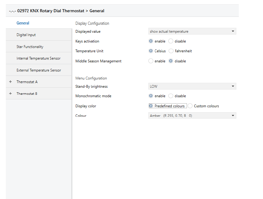
General
| ETS text | Values available | Comment |
| [Default value] | ||
|
Value shown on the display |
0 = Show Room tem- perature | You can choose whether to view on the display: the tem- perature measured, the fan coil speed and the valve status, no information, the temperature delta compared to the Setpoint set by the project |
| 1 = Current setpoint | ||
| 2 = Display Off | ||
| 3 = View Setpoint Dif- ference | ||
| [0] | ||
|
Button Activation |
0 = Enable | You can choose whether to make the thermostat buttons operative |
| 1 = Disable | ||
| [0] | ||
| Temperature Unit of meas- ure | 0 = Celsius |
Only for the display |
| 1 = Fahrenheit | ||
| [0] | ||
|
Mid Season Management |
0 = Enable |
To invert primary and secondary |
| 1 = Disable | ||
| [0] | ||
|
Stand-by brightness |
0 = Off |
Defines the bright- ness of the display when the thermostat goes on standby |
| 1 = Low | ||
| 2 = Medium | ||
| 3 = High | ||
| [0] |
N.B. By activating mid-season:
- the valve is deactivated and is never activated;
- the speed settings are activated/deactivated based on a setpoint to reach;
the 2nd stage of Cooling/Heating is activated based on the setpoint to be reached
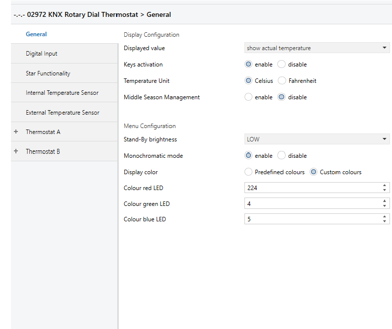
Monochrome mode to blend in the colors of the thermostat with those of the wiring series: Customised color (RGB setting)
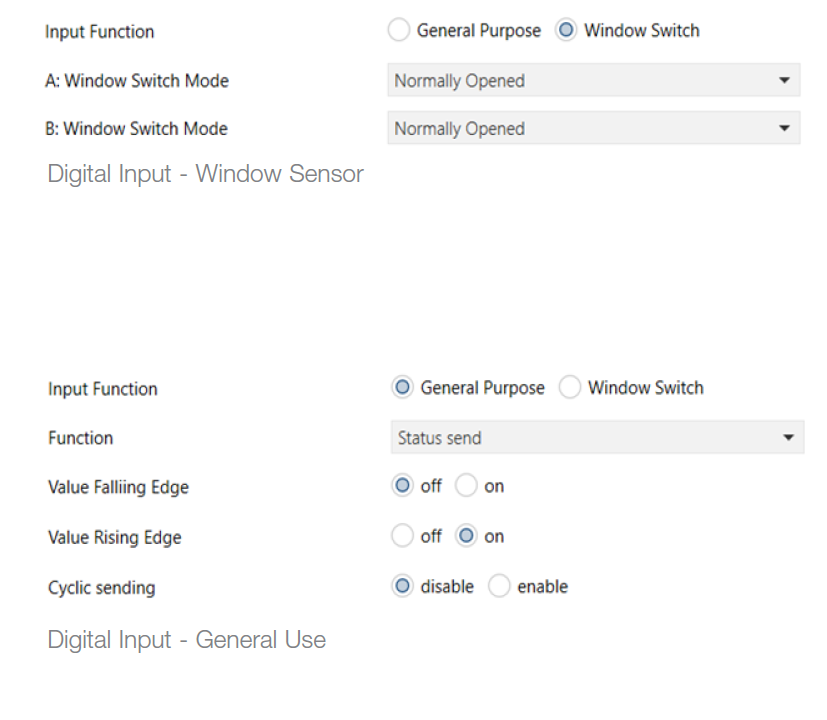
Digital Input
Digital Input Parameters
| ETS text | Values available | Comment |
| [Default value] | ||
|
Input Function |
0 = General Use | If set as “General use”, it also sends 0/1 over the bus towards a supervisor |
| 1 = Window Sensor | ||
| [0] | ||
|
Function (for gener- al use) |
0 = Switching on Rising Edge | Rising edge = close contact |
| 1 = Toggle on Rising Edge | Falling edge = open contact | |
|
2 = Switching on Falling Edge |
Switching = sends a 1 bit value (On/Off) on opening and the opposite on closing | |
|
3 = Toggle on Falling Edge |
Toggle = on every defined edge (opening or closure), On and then Off is sent to the cycle | |
|
4 = Status Send |
To send the contact status upon each switching and also cyclically. | |
| [0] | ||
| Window Sensor Mode (for thermo- stat-A and thermo- stat-B) | 0 = Deactivated | Defines whether the window sensor is normally open or closed. |
| 1 = Normally Open | ||
| 2 = Normally Closed | ||
| [0] | ||
Internal/External Temperature Sensor (Thermostat-A, Thermostat-B)
| ETS text | Values available | Comment |
| [Default value] | ||
|
Temperature Offset |
-2 °C….. +2 °C | Calibration of thermo- stat reading
(or of average of probes) |
| [0] | ||
|
Cyclic Send Time |
0…30 min. |
0=Off.
Activates cyclic send of object no. 0 “In- ternal Sensor” or no. 1 “External Sen- sor” (both for the thermostat A and for thermostat B) |
|
[0 = Off] |
||
|
Send on Change |
0.. 1.0 °C |
Sets the minimum measured tem- perature change with respect to the setpoint that will cause the thermostat to send the current value over the bus to a supervisor. |
|
[0 = Off] |
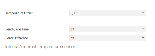
Note: If you use the Well Contact Suite supervision system to update the value displayed by the supervision station of the “A/B Current Temperature” linked to objects nos. 10 and 11, you must enable cyclic send or send on change. In the event of a conjunction of a high number of thermostats, it is not advisable to enable numerous cyclic sends with timing that is too low to avoid overloading the BUS communications.
Thermostat (A/B)
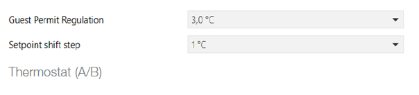
Guest control permitted
| ETS text | Values available | Comment |
| [Default value] | ||
|
Guest control per- mitted |
0 = Off |
Determine how much the guest can change the set- point from the value set on the thermostat (up/down) |
| 1 = 1.0 °C | ||
| 2 = 2.0 °C | ||
| 3 = 3.0 °C | ||
| 4 = 4.0 °C | ||
| 5 = 5.0 °C | ||
| 6 = None Limitation | ||
| [3] | ||
|
Setpoint shift step |
0.1, 0.2….1 | For thermostat A setpoint shift step upon receipt of control on objects 115 and 116 |
| [1]
|
Current Temperature (A/B)
| ETS text | Values available | Comment |
| [Default value] | ||
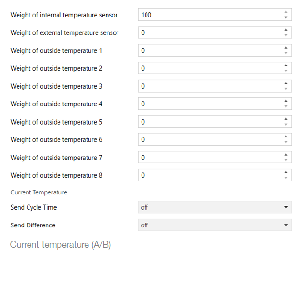
|
Temperature sen- sor weightings |
0… 100 |
For the thermostat’s internal sensor, the Vimar wired NTC probe (if present) and the KNX probes, this determines the relative importance for calculating the weighted av- erage of the measured tem- peratures |
|
[0] |
||
|
Cyclic Send Time |
0 = Off |
Sets the frequency in minutes with which the thermostat (A/B) must send the measured tem- perature value (or the weighted average of the probes) over the bus to a supervisor. Activates cyclic send of object no. 10 and
11 “Current Temperature” of thermostat A/B |
|
11 = 30 min. |
||
| [0 = Off] | ||
|
Send on Change |
0 = Off | Sets the temperature difference measured by the thermostat (A/B) that results in the read val- ue (or the weighted average of the probes) being sent over the bus towards a supervisor. Acti- vates cyclic send of object no. 10 and 11 “Current Tempera- ture” of thermostat A/B |
|
1.0 = 1.0 °C |
||
| [0 = Off] |
Setpoint (A/B)
Setpoint parameters
| ETS text | Values available | Comment |
| [Default value] | ||
|
Mode at bus power on |
1 = Comfort |
Thermostat operating mode at bus power on |
| 2 = Standby | ||
| 3 = Energy saving | ||
| 4 = Protect | ||
| 255 = Last Mode Selected | ||
| [255] | ||
|
Time between Heating and Cooling |
1 min. |
To avoid the formation of condensation with radiating systems during changes of season |
| 10 min. | ||
| 15 min. | ||
| 20 min. | ||
| 25 min. | ||
| 30 min. | ||
| 45 min. | ||
| 60 min. | ||
| [30] | ||
|
Dewpoint Supervision Time |
0 = Off |
Sets the time within which the thermostat must receive a message to the “Dewpoint” object from a device connected to a humidistat. A bit set to “1” will stop heating/air conditioning and set to “0” will cause it to restart. If messages have not arrived, when this time has elapsed heating/air con- ditioning will restart |
| 30 sec | ||
| 1 min. | ||
| 2 min. | ||
| 3 min. | ||
| 4 min. | ||
| 5 min. | ||
| 10 min. | ||
| 15 min. | ||
| 20 min. | ||
| 25 min. | ||
| 30 min. | ||
| [0 = Off] | ||
|
Cyclic Send Time |
0 = Off |
Sets the time for cyclic sending of temperature setpoint over bus towards a supervisor |
| 30 sec. | ||
| 1 min. | ||
| 2 min. | ||
| 3 min. | ||
| 4 min. | ||
| 5 min. | ||
| 10 min. | ||
| 15 min. | ||
| 20 min. | ||
| 25 min. | ||
| 30 min. | ||
| [0 = Off] | ||
|
Send on Change |
0 = Off |
Sets the minimum temper- ature change made by the guest with respect to the setpoint that results in the current setpoint being sent over the bus towards a supervisor |
| 0.1 °C | ||
| 0.2 °C | ||
| 0.3 °C | ||
| 0.4 °C | ||
| 0.5 °C | ||
| 0.6 °C | ||
| 0.7 °C | ||
| 0.8 °C | ||
| 0.9 °C | ||
| 1.0 °C | ||
| [0 = Off] | ||
|
Reset Setpoint Shift in Economy Mode |
Yes |
By selecting “Yes”, when the thermostat goes into Energy Saving (Economy) mode, the setpoint set by the user in Comfort and Standby mode is reset to the design default value. This function is useful for hotel appli- cations and with the Well Contact Suite supervision software. |
|
No |
||
|
[Yes] |
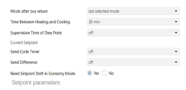
Important: The “Time between Heating and Cooling” parameter is the wait time it takes for the thermostat to switch from summer-winter and vice versa. This parameter is especially useful in some underfloor radiant systems where you set a high time value to prevent the formation of condensation; this applies especially when the thermostats work with a neutral zone and so there could be multiple seasonal changes in a single day. If instead, depending on the type of system, you want a faster response of the thermostat, it is necessary to reduce the value of this parameter.
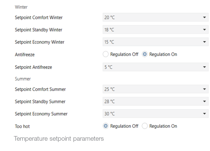
Temperature Setpoint (A/B)
| ETS text | Values available | Comment |
| [Default value] | ||
| Winter Comfort Setpoint | [20] | See “Range” table |
| Winter Standby Setpoint | [18] | See “Range” table |
| Winter Energy Saving Setpoint | [15] | See “Range” table |
|
Antifreeze |
0 = Control Off |
If you set “On” you can set the temperature the
thermostat goes to in “Protected” mode; if you set “Off”, when the thermostat is in “Protected” mode it will turn off tempera- ture control and will not send the current setpoint temperature |
|
1 = Control On |
||
|
[1 = 011] |
||
| Summer Comfort Setpoint | [25] | See “Range” table |
| Summer Standby Setpoint | [28] | See “Range” table |
| Summer Energy Saving Setpoint | [30] | See “Range” table |
Setpoint range
| Temp. °C | Temp. °C | Temp. °C | Temp. °C |
| 5 | 16 | 27 | 38 |
| 6 | 17 | 28 | 39 |
| 7 | 18 | 29 | 40 |
| 8 | 19 | 30 | 41 |
| 9 | 20 | 31 | 42 |
| 10 | 21 | 32 | 43 |
| 11 | 22 | 33 | 44 |
| 12 | 23 | 34 | 45 |
| 13 | 24 | 35 | |
| 14 | 25 | 36 | |
| 15 | 26 | 37 |
CAUTION: When the thermostat is in Neutral Zone mode, the breadth of this must be progressively increasing for the different operating modes of Comfort (minimum neutral zone breadth), Standby, Energy Saving, and Protected. This setting made with ETS ensures that, when the thermostat changes operating mode, the active setpoint is always at a suitable value and the thermostat does not start cooling if it was heating before or vice versa, causing considerable energy consumption
Continued
| ETS text | Values available | Comment | |
| [Default value] | |||
| If you set “On” | |||
| 0 = Control Off | you can set the temperature the | ||
| thermostat goes to in | |||
| “Protected” mode; if | |||
| Too hot | 1 = Control On | you set “Off”, when the thermostat is in | |
| “Protected” mode it | |||
| will turn off tempera- | |||
| [1 = On] | ture control and will not send the current | ||
| setpoint temperature |
Note: In the case of a 4-pipe system, the winter setpoint cannot take a higher value than the summer setpoint
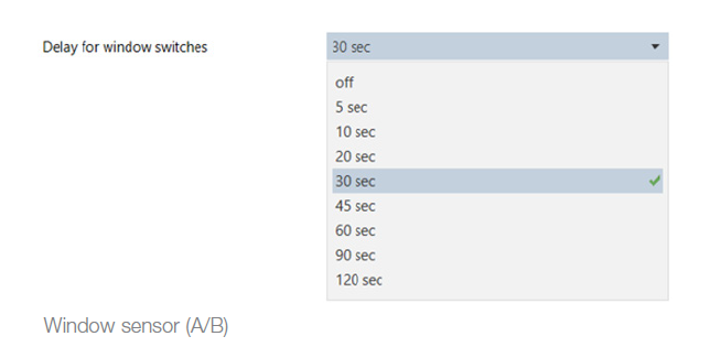
Window sensor (A/B) Sensor parameters
| ETS text | Values available | Comment |
| [Default value] | ||
|
Window sensor delay |
0 = Off | Sets the time delay that heating/air conditioning stops after window open detection |
| 8 = 120 sec. | ||
| [4 = 30] |
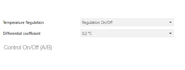
Control parameters
| ETS text | Values available | Comment |
| [Default value] | ||
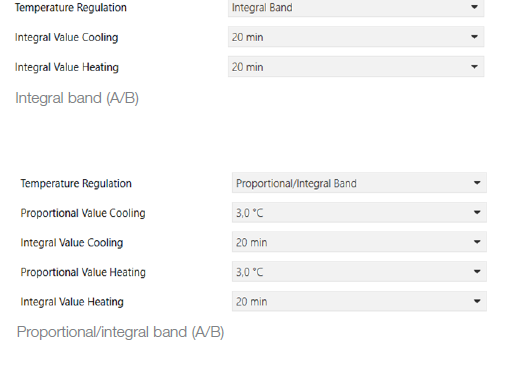
|
Control Temperature |
0 = Control On/Off |
Set according to the type of control required for the heat- ing/air conditioning system |
| 1 = Integral Band | ||
| 2 = Proportional/Integral Band | ||
| [0] | ||
|
Value Proportional Cooling |
1.0 °C |
To be set according to the characteristics of the system and the room (consult a heating engineer) |
| 1.1 °C | ||
| 1.2 °C | ||
| 1.3 °C | ||
| 1.4 °C | ||
| 1.5 °C | ||
| 1.6 °C | ||
| 1.7 °C | ||
| 1.8 °C | ||
| 2.0 °C | ||
| 2.2 °C | ||
| 2.5 °C | ||
| 3.0 °C | ||
| 3.5 °C | ||
| 4.0 °C | ||
| 4.5 °C | ||
| 5.0 °C | ||
| [3.0 °C] |
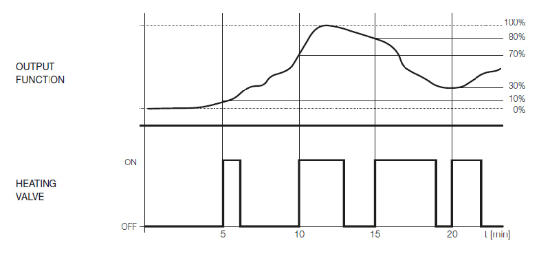
Proportional/Integral (PI) control
This type of control uses a more advanced algorithm that keeps the temperature inside the room more stable, increasing comfort. This algorithm works by switching the system on and off so as to be like a gradual increase or decrease in the system’s thermal (or refrigerating) power. To obtain optimal performance you need to perform the calibration according to the type of room and heating system.
Define the variables:
- Ta = room temperature
- Sp = current setpoint
- Kp = coefficient of the proportional component
- Ki = coefficient of the integral component
- Bp = proportional band
- Ti = integrative time
the algorithm is characterized by the following parameters:
- Proportional band: used to calculate the coefficient Kp = 100
- Bp and corresponds to the breadth of the proportional control band. Starting from the set temperature, this value is the temperature range in which the system power goes from 0% to 100%. For example: with the (heating) temperature set to 20.0°C and Band (P) =4.0°C, the thermostat runs the heating system at 100% when Ta is <= 16.0°C; as this temperature increases, the system power is consequently lowered down to 0% when Ta reaches 20°C. The value must be set taking account of the thermal capacity of the room to control; in general, it is recommended to use small values for rooms with a good level of thermal insulation and vice versa.
- Integrative time: used to calculate the coefficient Ki = Kp / Ti and corresponds to the time passed which, when equal to the deviation from the setpoint (error), the integrative component generates a contribution equal to that generated by the proportional component.
- The integral contribution reduces the error on full operation if thermal energy is lost in the room to be controlled, as this contribution increases according to the time during which the setpoint is not If this value is not set correctly, it can cause transients with variations around the setpoint or it may take longer to reach the setpoint.
Proportional integral PWM: PI control with On/Off valve
Continuous integral proportional: PI control with proportional valve
The parameters of the proportional and integral coefficients Kp and Ki are set using the ETS software: the proportional coefficient Kp for heating corresponds to the “Heating Proportional Value” parameter while the coefficient for cooling is set using the “Cooling Proportional Value” parameter. The integral time Ti is set with the “Heating Integral Value” and “Cooling Integral Value” parameters for heating and cooling, respectively. The PI control parameters should be set according to the type of heating or cooling system used, the size of the room and its thermal insulation.
IMPORTANT: Generally, when using fan coils, PI control is not used. The valve is typically managed with On/Off control and On/ Off valve or proportional valve (0%-100%); the fine adjustment is then made using the fan speed.
Continue
| ETS text | Values available | Comment |
| [Default value] | ||
|
Integral Cooling Value |
5 min. |
To be set according to the characteristics of the system and the room (consult a heating engineer) |
| 6 min. | ||
| 7 min. | ||
| 8 min. | ||
| 9 min. | ||
| 10 min. | ||
| 12 min. | ||
| 15 min. | ||
| 17 min. | ||
| 20 min. | ||
| 25 min. | ||
| 30 min. | ||
| 40 min. | ||
| 50 min. | ||
| 60 min. | ||
| 90 min. | ||
| 120 min. | ||
| [20 min.] | ||
|
Proportional Heating Value |
0 = Off | |
| 1.0 °C | ||
| 1.1 °C | ||
| 1.2 °C | ||
| 1.3 °C | ||
| 1.4 °C | ||
| 1.5 °C | ||
| 1.6 °C | ||
| 1.7 °C | ||
| 1.8 °C | ||
| 2.0 °C | ||
| 2.2 °C | ||
| 2.5 °C | ||
| 3.0 °C | ||
| 3.5 °C | ||
| 4.0 °C | ||
| 4.5 °C | ||
| 5.0 °C | ||
| [3.0 °C] | ||
|
Integral Heating Value |
0=Off | |
| 5 min. | ||
| 6 min. | ||
| 7 min. | ||
| 8 min. | ||
| 9 min. | ||
| 10 min. | ||
| 12 min. | ||
| 15 min. | ||
| 17 min. | ||
| 20 min. | ||
| 25 min. | ||
| 30 min. | ||
| 40 min. | ||
| 50 min. | ||
| 60 min. | ||
| 90 min. | ||
| 120 min. | ||
| [20 min.] | ||
|
Differential Coefficient |
0.1… 1.0 °C |
For On/Off type control: set the thermostat (A/B) hysteresis that determines activation/deactivation of
the system with reference to the difference between the setpoint and the measured temperature |
|
[1=0.2] |
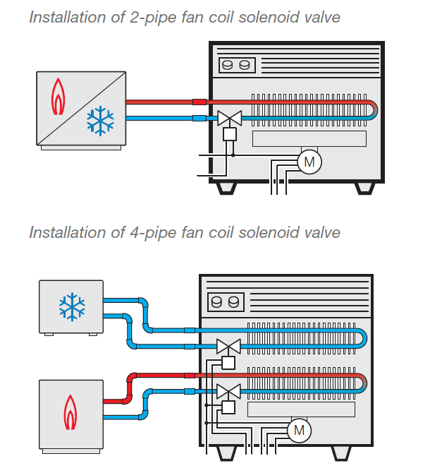
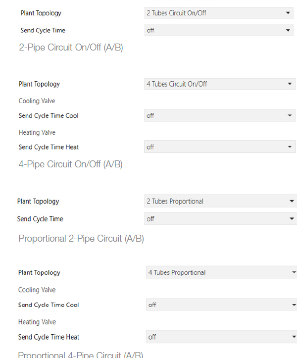
Valve (A/B)
Valve parameters
| ETS text | Values available | Comment |
| [Default value] | ||
|
System Layout |
0 = 2-Pipe Circuit On/ Off |
Select according to the type of installed system |
| 1 = 4-Pipe Circuit On/ Off | ||
| 2 = 2 Pipes Proportional | ||
| 3 = 4 Pipes Proportional | ||
| [0] | ||
|
Cyclic Send Time in Cooling |
0 = Off.. 30 min. | Sets the valve status send time to the associated actu- ators (parameter required for certain types of valves, for example Theben proportion- al valves, etc.) |
| [0] | ||
| Cyclic Send Time in Heating | 0 = Off.. 30 min. | |
| [0] |
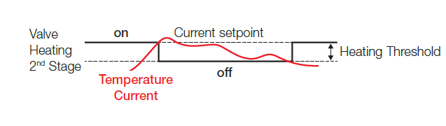
2nd Heating/Cooling Stage (A/B) “Boost”
The second stage is used to control a second heating or cooling source that allows the “boost” function. The “boost” function enables the second auxiliary source when the current temperature differs from the current setpoint by more than the set threshold. In this way, the main heating/cooling stage is assisted by the auxiliary source to reach the desired setpoint value faster. This feature is particularly useful for improving comfort in dynamic lens systems such as underfloor systems.
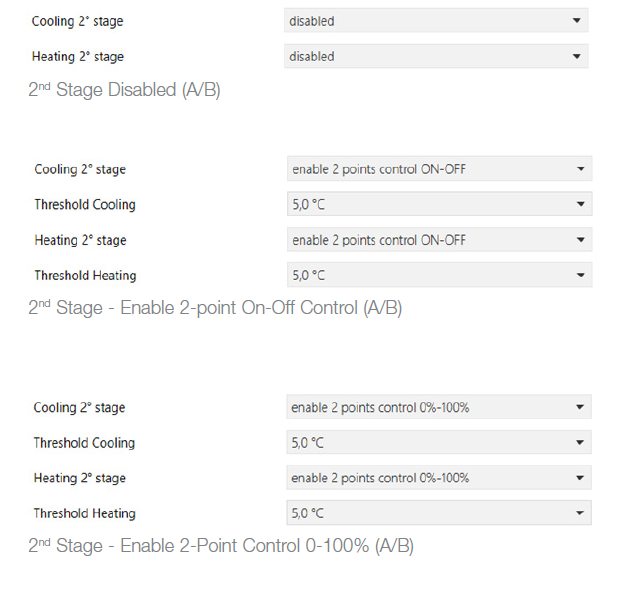
2nd Stage Parameters
| ETS text | Values available | Comment |
| [Default value] | ||
|
2nd Stage Cooling Valve |
Disabled |
Second cooling stage off |
|
Enable 2-point On-Off Control |
Control with object that sends on/off for valve status | |
|
Enable 2-point Control 0-100% |
Control with object that sends 0% for valve off status and 100% for valve on status | |
| Cooling Threshold:
– 0.5°C – 1.0°C – 1.5°C – 2.0°C – 2.5°C – 3.0°C – 3.5°C – 4.0°C – 4.5°C – 5.0°C |
Value of the trigger threshold in cooling mode |
|
|
2nd Stage Heating Valve |
Disabled |
Second heating stage off. |
|
Enable 2-point On-Off Control |
Control with object that sends on/off for valve status | |
|
Enable 2-point Control 0-100% |
Control with object that sends 0% for valve off status and 100% for valve on status | |
| Heating Threshold:
– 0.5°C – 1.0°C – 1.5°C – 2.0°C – 2.5°C – 3.0°C – 3.5°C – 4.0°C – 4.5°C – 5.0°C |
Value of the trigger threshold in heating mode |
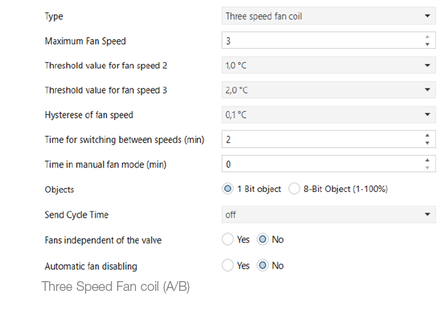
Fan (A/B)
Fan parameters
| ETS text | Values available | Comment | ETS text | Values available | Comment | ||
| [Default value] | [Default value] | ||||||
|
Type |
0 = Off |
No thermostat controlled fan coil.
Disables the graphics for the fan on the thermostat too. Useful when controlling only the solenoid valve for a radiator system |
Time in Fan Man. Mode (min.) |
0…255 |
Duration of “Manual Forcing” for the fan speed if the guest has forced the speed; after this time the thermostat returns to automatic mode. If the parameter is set to “0” it is interpreted as “Time = infinite” and the fan speed, set manually, stays on. To restore automatic opera- tion the guest must return the fan speed to AUTO by manually operating on the thermostat display. |
||
| 1 = Three Speeds Fan coil | Fan coil with 3 speeds | ||||||
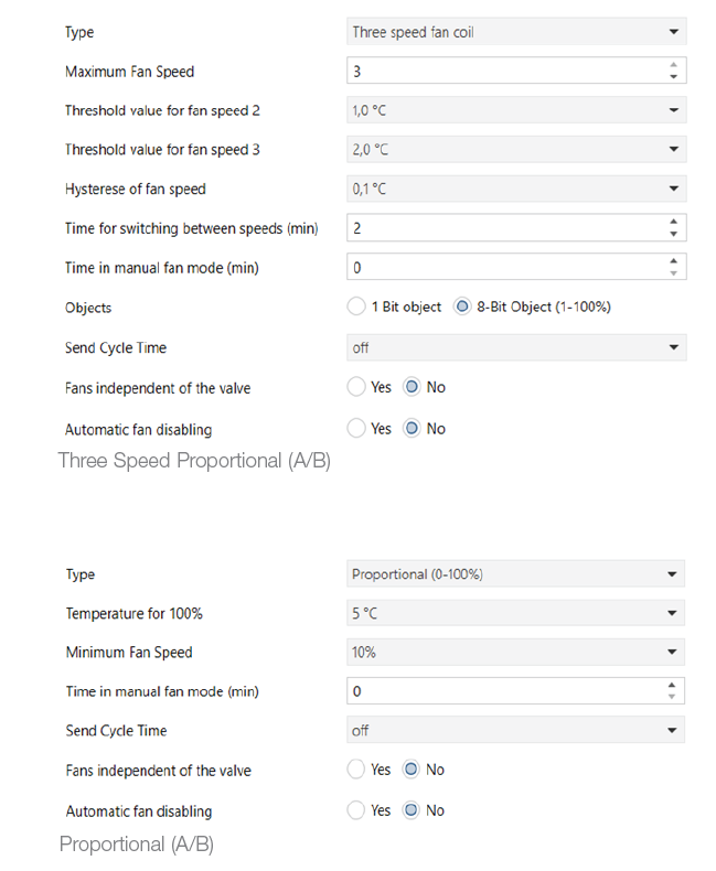
| 2 = Proportional
(0 – 100%) |
Proportional-speed fan coil |
[0] |
|||||
| [1] | |||||||
|
Maximum Fan Speed |
0 | Sets maximum fan coil speed.
Set “0” to control only the solenoid valve for a radiator system |
|||||
| 1 | |||||||
| 2 | |||||||
| 3 | |||||||
| [3] | |||||||
|
Objects |
0 = 1-bit object | Select type of object (1 bit for On/Off, 8 bits for propor- tional 1-100%) | |||||
|
Threshold for Fan Speed. 2 |
0.2 °C |
Sets the difference between the current temperature and the setpoint that triggers start of speed V-2 |
|||||
| 1 = 8-bit object (1-100%) | |||||||
| 0.3 °C | |||||||
| 0.5 °C | |||||||
| [0] | |||||||
| 1.0°C | |||||||
|
Cyclic Send Time |
0 = Off | Set cyclical sending over the bus for the fans | |||||
| 1.5°C | |||||||
| 11 = 30 min. | |||||||
| 2.0 °C | |||||||
| [0 = Off] | |||||||
| 2.5 °C | |||||||
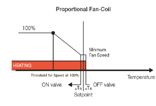
|
Threshold for Speed at 100% |
0 = 2 °C |
Absolute difference between setpoint and current tem- perature above which the speed goes to 100% |
|||||
| 3.0 °C | |||||||
| 1 = 3 °C | |||||||
| 3.5 °C | |||||||
| 2 = 4 °C | |||||||
| 4.0 °C | |||||||
| 4 = 5 °C | |||||||
| [1.0] | |||||||
| [4] | |||||||
|
Threshold for Fan Speed. 3 |
0.2 °C |
Sets the difference between the current temperature and the setpoint that triggers start of speed V-3 |
|||||
|
Minimum Fan Speed |
0 = 10% |
Minimum operating speed on fan activation |
|||||
| 0.3 °C | |||||||
| 1 = 20% | |||||||
| 0.5 °C | |||||||
| 2 = 30% | |||||||
| 1.0°C | |||||||
| 3 = 40% | |||||||
| 1.5°C | |||||||
| 4 = 50% | |||||||
| 2.0 °C | |||||||
| [0] | |||||||
| 2.5 °C | |||||||
|
Fans independent of the valve |
Yes |
Possibility of controlling the fans even with the valve off |
|||||
| 3.0 °C | |||||||
| 3.5 °C | No | ||||||
| 4.0 °C | |||||||
| [No] | |||||||
| [2.0] | |||||||
|
Automatic speed disabling |
Yes | Possibility of disabling the fan button on the display and objects 43 and 90 (Au- tomatic) | |||||
|
Fan Speed Hysteresis |
0.1 °C |
Hysteresis for the above-mentioned speed values |
|||||
| 0.2 °C | No | ||||||
| 0.3 °C | |||||||
| [No] | |||||||
| 0.4 °C | |||||||
| 0.5 °C | |||||||
| 0.6 °C | |||||||
| 0.7 °C | |||||||
| 0.8 °C | |||||||
| 0.9 °C | |||||||
| 1.0 °C | |||||||
| [1=0.1] | |||||||
| Switching Time between Speeds (min) | 0…255 | Time, in minutes, it takes to switch from one speed to another. | |||||
| [2] | |||||||
IMPORTANT: If you set “Switching Time between Speeds (min)” to 0 and leave a low value of “Fan Speed Hysteresis” (<0.5°C) there may be, near the speed change threshold temperatures, continual and repeated switching of the fan coil speeds that could damage it.
Manual operation of the fans
The user selects the speed used by the thermostat only when the valve is on; if the valve is off at the time of selection, the thermostat saves the setting and uses it again the next time the valve is on. On the display, the fan speed changes from “AUTO” to “OFF”. The selection made by the user remains active until the end of the time (in minutes) set by the “Time in Manual Fan Mode (min)” parameter or the fan speed is set manually onto “AUTO” with the![]() button or remotely via the communication object
button or remotely via the communication object
![]()
Caution: If the “Time in Manual Fan Mode (min)” parameter is equal to 0 it means that the manual operation of the fan is never turned off by time.
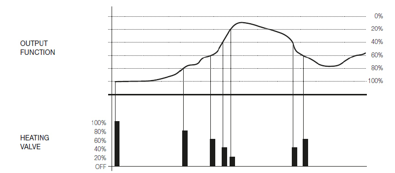
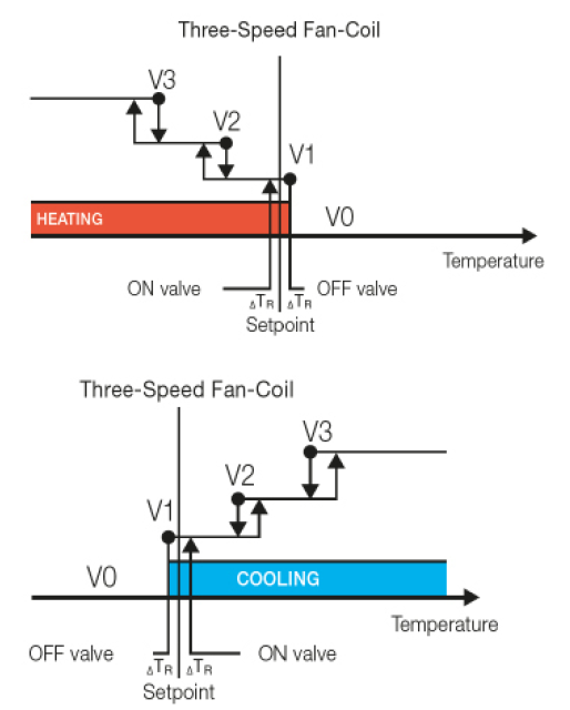
Automatic three-speed fan coil operation
In the case of a three-speed fan coil in “AUTO” mode, the fan coil speed is controlled automatically by the thermostat. The speed automatically goes from the higher to the lower speed gradually as the measured temperature approaches the value set as the setpoint. The threshold to determine the speed to set is linked to the following parameters: “Threshold for the Speed of Fan 2” and “Threshold for the Speed of Fan 3” while speed 1 is active when the valve is turned on and the “Switching time between speeds (min)“ has passed. An example of operation is shown in the following figure where SV2 and SV3 are respectively “Threshold for the Speed of Fan 2” and “Threshold for the Speed of Fan 3”; ΔTR is instead the “Differential Coefficient” of the on/off setting
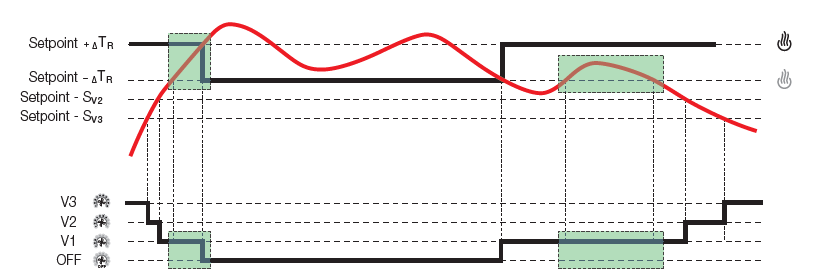
Note: In the example shown in the figure, the effect of the “Fan Speed Hysteresis” parameter was overlooked and the “Switching time between speeds” parameter was set = 0.
When the measured temperature reaches the setpoint the thermostat switches off the fan, sends a 1 bit on the Bus for object no. 45 or no. 92 “Off – Fan Outputs” (V0), switches on V0 and switches off V1. When the temperature deviates from the desired value, the valve is turned on and the speed V1, after the value of “Switching time between speeds”, is activated. In the following example figures, this parameter is set to 0.
N.B.: Fore reasons tied to the safety of systems, if the valve is active the user will be unable to set “OFF” from the thermostat. It will therefore be necessary to turn off the valve by setting the thermostat to another mode or by modifying its setpoint
Communication objects and ETS parameters
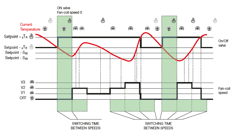
Switching Time Between Speeds
This is the time you need to wait for the activation of the speed after switching on the valve (allows the fan coil battery to reach the correct temperature before circulating the air). This parameter is also used between one-speed change and another to avoid continual speed switching near the thresholds.
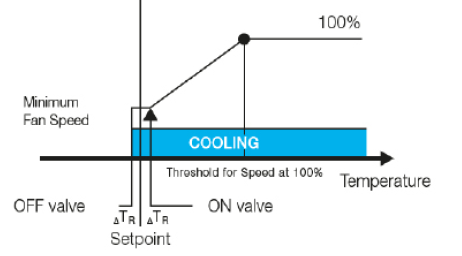
Proportional fan coil operation Proportional fan operation is similar to that of the three-speed fan coil. When the valve is OFF the proportional speed is equal to 0%; when the valve is ON the value of the proportional speed depends on the difference between the setpoint and the temperature measured in the room. The greater the difference, the higher the set proportional value of the speed. When this difference exceeds the value of the “Threshold for Speed at 100%” the proportional output of the fan is set to the highest possible speed which is 100%; when the difference is minimal the proportional speed is set to “Minimum Fan Speed”. The operation of the proportional fan, as for the three speeds, can be set automatically or, in manual mode, to the value invoked by the thermostat button or set by the object “Proportional (0-100%)
N.B.: Fore reasons tied to the safety of systems, if the valve is active the user will be unable to set “OFF” from the thermostat. It will therefore be necessary to turn off the valve by setting the thermostat to another mode or by modifying its setpoint.
Scenario (A/B)
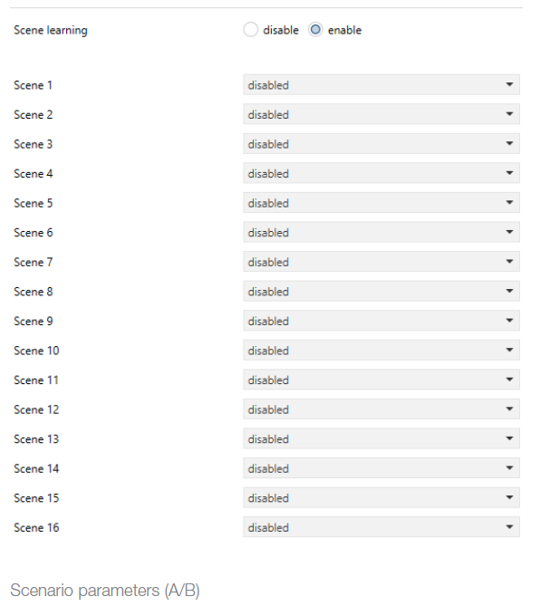
16 scenarios are available. 16 different scenarios can therefore be saved on the device output. With Enable Scenario Learning you can also set the status of the output for the desired scenario with a message from the bus (scene learn).
| ETS text | Values available | Comment |
| [Default value] | ||
|
Scenario Learning |
0 = disable | To enable scenario thermo- stat learning |
| 1 = enable | ||
| [0] | ||
|
Scenario |
0=disabled |
To define the operating mode when the scenario is called up. |
| 1=Comfort | ||
| 2=Standby | ||
| 3=Energy saving | ||
| 4=Protected | ||
| [0] | ||
|
…Scenario 16 |
0=disabled |
To define the operating mode when the scenario is called up. |
| 1=Comfort | ||
| 2=Standby | ||
| 3=Energy saving | ||
| 4=Protected | ||
| [0] |
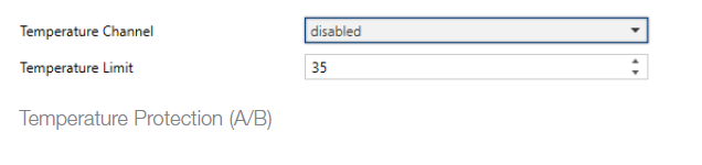
Temperature Protection (A/B)
This function is used to limit the temperature of the area controlled by the thermostat
Temperature Protection Parameters
With the “Temperature Channel” parameter you select the temperature to be monitored; when, in heating, it exceeds the value selected with the “Temperature Limit” parameter, the thermostat changes its operating mode and switches OFF sending an alarm signal with the object Floor Temperature Alarm. The thermostat comes out of the alarm condition when the temperature drops below the set threshold and the user changes the thermostat operating mode. The typical application for this function is that of limiting the maximum temperature of the floor
| ETS text | Values available | Comment |
| [Default value] | ||
|
Temperature Channel |
0 = Disabled | Limitation disabled |
|
1 = Internal Sensor |
The internal sensor is used for temperature limitation | |
|
2 = External Sensor |
The external sensor is used for tempera- ture limitation | |
|
3 = External Temperature 1 |
The External Tem- perature 1 is used for temperature limitation | |
|
4 = External Temperature 2 |
The External Tem- perature 2 is used for temperature limitation | |
|
5 = External Temperature 3 |
The External Tem- perature 3 is used for temperature limitation | |
|
6 = External Temperature 4 |
The External Tem- perature 4 is used for temperature limitation | |
|
7 = External Temperature 5 |
The External Tem- perature 5 is used for temperature limitation | |
|
8 = External Temperature 6 |
The External Tem- perature 6 is used for temperature limitation | |
|
9 = External Temperature 7 |
The External Tem- perature 7 is used for temperature limitation | |
|
10=External Temperature 8 |
The External Tem- perature 8 is used for temperature limitation | |
| [0] | ||
|
Temperature Limit |
10…70 °C |
Limit of the tempera- ture channel beyond which the limitation trips |
| [35] | ||
FAQ
- hich thermostat objects must be used in the ETS project? For each one, should a dedicated ETS group be created or should “common groups” be created? For the objects listed below, you must create a separate group for each data point of each thermostat:
In general:- Thermostat A: 13 – 63.
- Thermostat B: 64 -113.
Specifically: - 12 if Thermostat B is present.
- 39 if it is a 4 PIPE system and there is a COOLING valve. 90 for thermostat B.
- 43 if a proportional fan coil is present. 94 for Thermostat B.
- 57 if a window contact that must deactivate climate control is present, 108 for Thermostat B.Note.
You could also create a general group with the Summer/Winter control of all the thermostats (DATAPOINT 22 for Thermostats A and 72 for Thermostats B), but if it is a system in which there is the Well-contact Suite supervision software we recommend that you create a group for each single Thermostat A and for each single Thermostat B.
- What does the “Thermostat Mode” object represent?It refers exclusively to the mode the thermostat is currently in (or the mode you want to put it into given that the corresponding object is also present in write mode).
It does not indicate whether it is summer or winter. The possible options are:- 01 = Comfort
- 02 = StandBy
- 03 = Economy
- 04 = Protect/Off
- To see whether the thermostat is in Off mode you can go and read object 16 “Off A: Mode – control” or object 67 “Off B: Mode – control” which will answer 1 if the thermostat is Off or 0 if it is in another operating mode.
- What difference is there between the “Protected” object and “Off” in the “Antifreeze-Too Hot” operation?
The “Protected” object is used and acts as Off in the event that the “Temperature Setpoint” parameters and the items “Antifreeze” and “Too Hot” are set to “Control Off”. So in this case when the object “Protected” is activated, the thermostat entirely disables temperature control and does not even send its current setpoint over the bus. In normal installations it is therefore recommended to set “Control On” on the parameters “Antifreeze” and “Too Hot” and to set the corresponding two temperatures. This avoids the risk of frozen pipes in the winter and excessive room overheating in the summer. The “Off” mode on the other hand also inhibits “Too Hot” and “Antifreeze” and should never be used in normal installations. The “Off Mode“ object turns off the thermostat even if the temperature falls below zero (i.e. it does not activate Heating/Air conditioning). It is advisable to use the “Protected” object, which switches the thermostat to Off or protected (Antifreeze) depending on how the relevant parameters are set (summer or winter). - What is the function of the “Thermostat Off” object and what applications can it have?
Thermostats have various objects created for operation with our Well-contact Suite hotel software. The “Thermostat Off” object blocks thermostat bus communication (both reception and transmission). This function is dedicated to Vimar supervision software. - What is the function of the “Off” mode and what applications does it have?
The “Off Mode” object turns off the thermostat even if the temperature falls below zero (i.e. it does not activate Heating/Air-conditioning). It is advisable to use the “Protected” object, which switches the thermostat to Off or protected (Antifreeze) depending on how the relevant parameters are set (summer or winter). - What is the function of the “Comfort” object?
Unlike the “Energy Saving”, “Protected” and “Off” objects, which do not permit the sending of a “0” bit, if the “Comfort” object is set to “1”, the thermostat switches to comfort mode at the design temperature or at the custom temperature previously set by the guest. If this object is set to “0” the thermostat switches to standby mode (at the design temperature or at the custom temperature previously set by the guest). - What is the function of the “Summer Protected” object?It is the protected mode setpoint in air conditioning operation. It corresponds to the protected mode in heating operation (with air conditioning operation it cools if the temperature exceeds the setpoint whereas with the heating operation, it heats if the temperature falls below the setpoint).
- On thermostats 20542, 16922 and 14522 a single bit was used to activate/deactivate antifreeze. What is used now?
The “Protected” object (summer or winter) is used.
Note. Antifreeze (or its analog “Too Hot”) must be active in the object parameters so as not to obtain an Off. - On thermostats 20542, 16922, and 14522, to deactivate “Antifreeze” mode it was sufficient to send a “0”. What needs to be done with the new thermostats? Do you need to change mode, for instance, “Economy”?Yes, the installer decides whether the user can turn the system off or set it to “Antifreeze” mode. Depending on the set ETS parameters, the thermostat switches to “Antifreeze” mode and returns to the previous mode only when the window is opened and closed, whereas if the thermostat is set to “Protected” mode from the bus, it will subsequently be necessary to change the mode.
- On thermostats 20542, 16922 and 14522, a single bit was used to read the antifreeze status; in supervision, single bits (“0” or “1”) and not bytes are required. Where is this object/status to be found?
The KNX system uses the 1-byte object “Thermostat Mode” to read the status of the thermostat. If you do not want to use the Byte, you can set the 1-bit mode change object to read. However, this is not the ideal solution because the bits will have to be read explicitly given that the information is not sent automatically. - Are there any particular precautions to take when using the 0-100% proportional valve control?
Never use the “Control Value” object. This is a debug object left inside the application for KNX certification purposes. In this specific case replace it with a “Cooling Valve” to obtain the desired function.
However, some types of valves with proportional control require a cyclic refresh of the control value. In this case it is necessary to activate cyclic sending of the control value to the valve. To control the proportional solenoid valves you must use the “Cooling/Heating Valve” object in read/write mode (which appears only for “2-Pipe Proportional” systems, selected by the parameter “Valves”) or objects “Cooling Valve” and “Heating Valve” will appear if “System Type” is set with the “Proportional 4-Pipe Circuit” parameter. - We need to have a group that goes to “0” when the thermostat is set to “Off” (by the guest or the supervisor) and returns to “1” when the thermostat is returned to “CMF”. How can we do this?
This is an application that allows the input of a Daikin with KNX interface to be forced so that it turns the machine off if the thermostat is Off and back on if it is “CMF” without necessarily starting the system (heating is subsequently activated depending on the messages sent by the thermostat to the valve). In practice the guest wants to use the thermostat for On/Off control of a device that has its own temperature control function.
To do this you have to use an object (such as a KNX logic) that sends an On/Off message according to the thermostat mode (using the “Mode” object). - How should a window’s N.C. contact be managed when it is connected to the thermostat for window open signaling?
The input to which the window contact is connected must be set with the “Status Send” function so that one message is sent when it is opened and another one when it is closed. If an N.C. contact is used, it will be necessary to set “Off” for the falling edge (opening of window and contact) and “On” for the rising edge (closing of the window and contact). If the contact is an N.O. type, the two parameters must be set respectively to “On” and “Off” (when the window is opened the contact is closed and vice versa). If you set the input as “Window Sensor”, opening the window will stop the thermo-stat from writing an “04” byte (antifreeze) to the datapoint “Mode status” and “00” to the datapoint “Cooling/Heating Valve” (closes the valve); closing the window will set the previous status; you can also choose a delay time for opening the window after which the thermostat will stop. If together with this internal thermostat management you also want a “0” bit to be sent to the bus when the window is opened and a “1” bit when it is closed, you must set the thermostat IN input as “General Use” so as also to display object no. 110 “Input”. If the window contact is connected to the thermostat input, this new object must be associated with a group with the “Window Sensor” object, whereas if you use the IN input of another KNX device this will be associated with the “Window Sensor object. - Which functions are considered most important for use of the thermostats on hotel systems with the Well-contact Suite management/supervision (and other) software?
- Current Temperature: this is useful for displaying the thermostat temperature in the software (it is advisable to set cyclic sending amongst the parameters; to be considered in the event of a large number of devices).
- Thermostat Mode or alternatively Comfort, Energy Saving, Protection: these are important for sending thermostat operating mode controls via Well-contact Suite.
- Thermostat Mode – status: this is important to see the current operating mode of the thermostats in the software.
- Summer/Winter status: this is important to see the current seasonal operating mode of the thermostats in the software.
- Enable Summer/Winter: this is essential for sending seasonal thermostat operating mode controls via Well-contact Suite software.
- Current Setpoint: this is useful for displaying the set thermostat temperature in the software (it is advisable to set cyclic sending amongst the parameters; to be considered in the event of a large number of devices).
- Winter Comfort Setpoint, Winter Standby Setpoint, Winter Energy Saving Setpoint, Winter Protected Setpoint, Summer Comfort Setpoint, Summer Standby Setpoint, Summer Energy Saving Setpoint, Summer Protected Setpoint (objects from 28 to 35 and from 79 to 86): they are useful for displaying and setting the various “Basic Setpoints” in the two seasonal operating modes in the software.
- Management case studies Heating/air conditioning speed for thermostats
- To perform supervision of thermostats using Vimar Well-contact Suite software, what communication objects need to be set?
YOU have to set to “Read” the relevant flags of objects from 28 to 35 and from 79 to 86 for each 02972 thermostats. - What is the parameter “Time in Manual Fan Mode” used for?
It is a time indicated in the parameters for which the thermostat remains in “Manual forcing” if the guest has manually forced the temperatures or speed of the fan coil: when this time has elapsed the thermostat returns to automatic. If the parameter is set to “0” it is interpreted as “Time = infinite” and the manual forcing stays on. An object is needed that goes to “1” if one of the 3 speeds is activated and returns to “0” if V 1/2/3 are deactivated. Use the object “Cooling/Heating valve”. - Is it possible to take an object to “0” when a speed V-0 is set from the thermostat?No, it is not possible to set the speed V-0 manually.
- Is the object “Thermostat Mode – Mode” (objects 17 and 68) usable only by Well-Contact Suite or also by other supervision software?
- Is it possible to manage a general valve if there is more than one thermostat?
This function is possible only with a logic module. It is also possible to use a Well-contact Suite functional logic, which will operate only if the supervision software is active and communicating with the bus. - Is it possible to control a proportional-type fan coil with one or two supply values?
The thermostat normally controls supply at three levels of intensity: 33%, 67%, 100%. As can be seen in the following image, setting the maximum speed to 1 or 2 results in one or two thresholds (respectively 33% or 33-67%). Other supply-level settings are not possible. For the TACTIL thermostat 02972 you can still control the proportional fan coil with a minimum speed settable from 10% to 50% and with a maximum speed up to 100%. The object “Thermostat Mode – Mode” is a KNX standard object, with coding defined by the standard (HVAC Operating Mode 20.102), therefore it can also be used by other super-vision software; there is also the related object for reading the mode (objects 18 and 69).- 0 = Automatic
- 1 = Comfort
- 2 = StandBy
- 3 = Economy
- 4 = Protection
- 5-255 = Reserved values
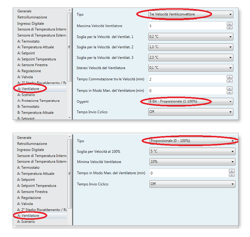
- Is it possible to control an On/Off type radiant heating system and a fan coil air-conditioning system with 3 speeds?
You have to work prevalently with the thermostat object “Enable Summer/Winter”. Firstly, the type of system must be piped On/Off. Next, configure all the standard data points - required by the thermostat to operate correctly. Add the following groups: group 1 “Enable – Summer/Winter”: to perform the season change
on the thermostat and disable the 3 speeds:- “Speed V1 – Disable fan”
- “Speed V2 – Disable fan”
- “Speed V3 – Disable fan”
- “Status – Summer/winter”
- oup 2 To operate the radiating system with On/Off valve in winter:
- “Heating valve – valve”
- “Relay” (the relay of the device controlling the underfloor system valve)
Note: you can add to the group the object “Fan coil: Disable Local Operation” to disable the user interface of the fan coil during the winter season. group 3 To operate the fan coil general On/Off valve in the summer:- “Cooling valve – Valve”
“Relay” (the relay of the device controlling the fan coil valve). group 4 - To control the fan coil speed V1 in summer: “Relay” (the relay of the device controlling the speed-1 of the fan coil)
- “Speed V1 – Fan Outputs”. group 5
- To control the fan coil speed V2 in summer: Relay” (the relay of the device controlling the speed-2 of the fan coil)
- Speed V2 – Fan Outputs”. group 6
- To control the fan coil speed V3 in summer: “Relay” (the relay of the device controlling the speed-3 of the fan coil)
- “Speed V3 – Fan Outputs”.
In this configuration, when the thermostat is in Winter mode, group 1 goes to “1” so the fan coil speeds are forcibly disabled to block their operation and the thermostat operates in On/Off only on the radiant heating valve as it is configured for 4-pipe On/Off systems with group 2; in Summer group 1 goes to “0” and the 3 speeds can again be controlled from the bus; furthermore, the thermostat will operate with the general fan coil cooling valve of group 3. Groups 4, 5 and 6 are those of the 3 speeds and objects for the thermostat and they can be controlled from the thermostat when the first group goes to “0” by setting the thermostat in summer mode.
- “Cooling valve – Valve”
- What objects are used to read the thermostat temperatures from the Well-Contact Suite software?
For thermostats 02972, objects 11 and 12 (weighted averages of the temperatures that can be associated) are used to read respectively the current temperatures of thermostats A/B, and not objects 0 and 10 of the device (which are the precise measurement data for the individual internal/external probes). - Is it possible to eliminate the adjustment range in Comfort mode, which can be expanded at the most to ± 5°C?
It is possible by setting the parameter “Guest Control Permitted” onto “No Limitation”. - If a 0-100% proportional fan coil rather than a three-speed fan coil is controlled, will values 0-100% be sent to the fan coil?
Yes, if the “Type” fan parameter is selected on the “Proportional (0-100%)”. - How is the “Dewpoint” object used?
This object is used in systems with underfloor cooling and is associated with a KNX humidistat capable of detecting a level of humidity at which condensation may form on the floor. By activating the ETS group for this object, the thermostat will automatically go to “Off” mode, stopping air conditioning. It is possible to set a time limit after which the thermostat will automatically go to “Off” if a message has not arrived from the KNX humidistat. This operation does not occur in heating mode. - How does the “Comfort” object work?
If “1” is sent to this object, the thermostat goes to “CMF” mode (unless the window has been opened in the event of window-contact control); if “0” is sent the thermostat goes to “Standby” mode - IS it possible for a thermostat to control a 0-100% proportional valve and an On/Off valve simultaneously?
No, it is not possible as setting the thermostat for proportional control disables On/Off control on the valve object. With two-zone thermostats (02952, 20430 and similar), it is possible to operate “Thermostat-A” in one mode and “Thermostat-B” in the other, but the guest would have to set both each time to activate both the proportional valve and the On/Off valve. - Can the thermostat be controlled from supervisors such as the KNX touch screen?
Yes, the thermostats are KNX standard so a KNX-certified supervisor is capable of managing them. - How can operations be performed by the guest on the thermostat (change of temperature and functions) be inhibited?
Using the objects “Temperature: Disable Local Operation” and “Fan coil: Disable Location Operation” you can block changes to fan coil temperature and speed. It is not possible to block the operating mode because the guest cannot decide this directly. For example, the guest can force the thermostat to Off only by opening the window or can set it to standby only by leaving the room (removing the card from the pocket reader). - If a 1-bit thermostat comfort/stby object is associated with the “Guest in room” pocket object, when the Wellcontact Suite software is started up, the thermostats that were in “Economy” or “Protected/Off” mode return automatically to STBY with higher setpoints.
The “U” flag must be disabled in ETS for the thermostat object. If the “Guest in room” pocket object is associated with the 1bit “Stby/Comfort” thermostat object, when a guest enters the room goes to “Comfort” mode. If within the same group the “R” read flag is enabled on the pocket object to allow the presence of a guest in the room to be interrogated by the WCS software, when it starts, the software performs interrogation polling on this group and the pocket responds with a “0” bit for the “Guest in room” object. If the flag “U” is active in that thermostat object, it takes the pocket response as an update for its operating mode and goes to Stby when perhaps it had been set to “Economy” mode or “Protected/ Off” mode for an extended period of non-use of the room. - How can I update the thermostat setpoints and measured temperatures on a supervisor (e.g. Well-contact Suite)?
To have the new setpoint status once a new setpoint has been set on the supervisor (regardless of the mode currently being used) you must go to the “SETPOINT” and “SENSOR PARAMETERS” parameters of the thermostat and set the values of “Send on Change” and “Cyclic Send Time” as preferred: if the system is very large you should perhaps set the send-on difference to 0.3-0.5°C and not set the periodic send every x minutes so as not to overload the Bus with messages. - Is it possible to operate a thermostat in such a way that in the summer it controls a 0-100% proportional valve and in the winter a simple head in On/Off mode?
Yes, this can be done by means of special programming of the thermostat and relay device that we will now look at in greater detail, provided the On/Off head is not controlled by the relay on the thermostat (which does not have the logic function described below) but by a relay of other devices such as an 01523.1 or a 14457, etc.. YOU have to set the thermostat VALVE parameter to “4 pipe proportional with proportional/integral control” mode. This way you have 2 separate “1 byte proportional valve” objects for each season and will use only the one for the summer (whereas for the winter you will not use the corresponding 1 byte object). For winter mode, set the thermostat FAN parameters as “Maximum speed 1”, in other words use the corresponding object of “Speed-1” given that when the winter valve is activated by a thermostat heating request, this object will certainly also be activated. Given that the thermostat’s season change object goes to “1” in winter status and “0” if you set the summer season, you can then work with a relay, for example a 01523.1 on which you can activate the parameter “1 OBJECT LOGIC function” (setting it in “AND” mode). You can then create a first group with the “On/Off control” of the relay together with the “Speed 1” object of the
thermostat (this serves to control the heating head) and then another group with “object no. 18 summer/winter status” of the associated thermostat together with the object “Logic 1” of relay 01523.1. In functional terms, in winter the “logic 1 of 01523.1” group is activated, so when the other group (i.e. that of the thermostat object + relay On/Off control) also goes to 1, the relay 01523.1 will switch towards the head. In summer the first of the two groups will be constantly at “0”, so the On/Off messages reaching the 2nd group from the thermostat object will not cause the relay to move. - Is it possible to control a fan coil by using any free relays of the various devices without using the 4 I/O device (art. 01522.1) or the relay actuator (art. 01523.1)?
Yes, it is possible; however, to prevent the user via supervision from mistakenly activating a speed relay while a similar relay is also activated by the thermostat, it is necessary in the ETS project to avoid pairing the force–speed objects nos.
45 – 48. - In a hotel, the thermostats set to OFF/Economy mode suddenly all go into STBY mode; why is that?
The mode change has been generated by the Well-contact Suite software reopening which on starting up queries all the room pockets to update its supervision on the presence or absence of guests in the rooms; the pockets respond with a bit=0 on the presence, but this is the same group that is also linked to the 1 bit object of the CMF/STBY control of the thermostats and bit=0 on that group entails an interpretation of the thermostat of the type “guest not in room, go onto STBY “. The problem can be solved by disabling the Update flag “U” on the 1 bit object of “comfort/stby” of the thermostat that is active by default; in this way, when the Well-contact Suite software queries the pockets, they respond with a bit=0 on the group but since that flag is OFF, the thermostat will keep its mode without going onto STBY. - If the thermostat is operating in Neutral Zone mode and the guest changes the current setpoint by adjusting the thermostat, what happens? Are the setpoints previously set by ETS or by Well-contact Suite also changed?
No, nothing in particular happens. Acting on the thermostat changes only the Current Setpoint and not the single mode/ season setpoints, the thermostat functions according to the set setpoint and the room temperature so it will activate the heating, cooling or remain in the neutral zone depending on the heating and air-conditioning setpoints of the current mode. - You cannot change the thermostat mode from the Well-Contact Suite software (neither from supervision nor from the Master-thermostat); What can be done?
To send mode messages to the thermostats, the Wellcontact Suite software uses communication objects No. 17 for thermostat-A and No. 68 for thermostat-B. - Is it possible to control a fan coil via a relay belonging to different devices and not to a 4-output module?
Yes, it is possible. The thermostat automatically performs an interlocking function between the relays of the various speeds so it deactivates the relay in use before activating that of the new speed to switch on; to prevent the guest from accidentally activating the 2 relays at the same time causing failure of the Fan coil, in the ETS project it is necessary not to pair the speed-forcing objects to avoid the guest forcing one speed when another one is already in use (it is not possible to interlock relays of different devices). - Can the various Setpoint communication objects be added to the same ETS group?
No, each thermostat communication object must be added to its own dedicated group. - Is it possible not to show the icon for swapping between Thermostat A and Thermostat B on the display?
Yes. So as not to display the icon on the bottom left you need to Disable the “Enable User Interface” item of the “Thermostat B” parameter. - Using the Setpoint Shift object and resetting this setting when you switch the thermostat to ECONOMY or OFF/ PROTECTED mode.
If with a supervisor device (touch screen, web server, etc.) you change the current setpoint of a thermostat, in which the Reset Setpoint Shift in Economy Mode parameter is set = yes, via the SETPOINT SHIFT object and, at a later time, you bring it into ECONOMY mode, when the thermostat is put back in STBY or CMF mode the value previously set by the supervisor will not be maintained (conversely, if youwrite the value directly on the SUMM/WINT COMFORT SETPOINT object or on SUMM/WINT STBY SETPOINT there will not be a reset when the mode changes). - Is it possible to have a Boost function to supplement the heating? And will this make it possible to determine the 3 speeds of the fan coil?
The section of the parameters referred to as “2nd HEATING/ COOLING STAGE” illustrates how the thermostat is able to activate an additional system, which will only be on/off, or control of a proportional valve 0-100% by means of the objects Nos. 36 and 37 which will appear by activating this Boost function. The thermostat is not able to manage the Boost function by determining the speeds with 3 relays so either it will be on/off or proportional 0-100% (whose possible value is either 0% for power-off or 100% for fully open). - Is it possible to have the thermostat 02972 send a 1 bit ON message when the thermostat turns off all the speeds?
Yes, and this function is required by some temperature control gateways to manage the Off of the fan coils when the thermostat has switched off the speeds: the communication object is called “OFF – Fan outputs” and the thermostat automatically sends a bit=1 when the fans are turned off and bit=0 when they are turned back on. - If the speeds of the fan coils are forced to OFF, will the thermostat reset to AUTO when it changes mode or simply when Well-contact Suite queries the room pocket to know whether the guest is present in the room?
When Well-contact Suite queries a pocket it responds with a bit equal to 0/1 on the same control group as the CMF/ STBY mode of the thermostat causing the mode control to be sent again. The thermostat is designed to reset forcing when it receives a mode control so it eliminates the forcing- OFF of the fans; to work around this problem, in the ETS project you can remove the “U” flag of the object of CMF/ STBY and reprogram the thermostat so that the response sent from the pocket to the Well-contact Suite software is ignored. - How does the “Neutral Zone” mode function for a 4-pipe system?
If the “Enable Summer/Winter” object of thermostat A and/ or thermostat B is not paired with any ETS group, the the thermostat in question will function in Neutral Zone mode; in this mode it will be the thermostat that activates the Air- Conditioning or Heating circuit depending on the room temperature, the Summer and Winter setpoints for the currently selected mode (CMF/STBY/etc.) with a room temperature range, called Neutral Zone, within which neither circuit will be activated. If the end user increases or decreases the setpoint by using the thermostat it will not change the two summer/winter setpoints but will change a setpoint that is halfway between those two values which is the central reference of the neutral zone; raising or lowering this value will also automatically increase or decrease the two setpoints related to summer/winter for the active mode (CMF/STBY) so as to keep the neutral zone unchanged. The thermostat activates the heating or air-conditioning according to the two summer/winter setpoints so, if the room temperature is not in the neutral zone, the thermostat will take as reference the setpoint that is closest to the current temperature (summer/ winter) resulting in the activation of the heating or air-conditioning circuit.
Proportional Three-Speed Control:
- Proportional (0-100%) – Fan Inputs: useful for sending the proportional speed maximum value.
- Proportional (0-100%) – Fan Outputs: useful for displaying the proportional speed maximum value in the software.
On/Off management:
- Speed V1 – Fan Inputs, Speed V2 – Fan Inputs, Speed V3 – Fan Inputs, Automatic – Fan Inputs: useful for sending speed force controls to the thermostat or for forcing automatic control.
- Off – Fan Outputs, Speed V1 – Fan Outputs, Speed V2 – Fan Outputs, Speed V3 – Fan Outputs: useful for displaying the current speed of the fan coil.
- Speed V1 – Disable Fan, Speed V2 – Disable Fan, Speed V3 – Disable Fan: useful for sending speed to disable controls.
Viale Vicenza 14 36063 Marostica VI – Italy www.vimar.com
Reference:
Download Manual:
Leave a Reply