
VRC 720 sensoCOMFORT Programmable Thermostat

Safety
Intended use
In the event of inappropriate or improper use, damage to the product and other property may arise.
The product is intended for using an eBUS interface to control a heating installation with heat generators from the same manufacturer.
The system control controls based on the installed system:
- Heating
- Cooling
- Ventilation
- Domestic hot water generation
- Circulation
Intended use includes the following: - Observance of all other applicable documents for the product and any other system components
- installing and setting up the product in accordance with the product and system approval
Intended use also covers installation in accordance with the IP code.
This product can be used by children aged 8 years and above and persons with reduced physical, sensory or mental capabilities or lack of experience and knowledge if they have been given supervision or instruction concerning the use of the product in a safe way and understand the hazards involved.
Children must not play with the product.
Cleaning and user maintenance work must not be carried out by children unless they are supervised.
Any other use that is not specified in these instructions, or uses beyond that specified in this document, shall be considered improper use.
General safety information
Risk caused by inadequate qualifications
The following work must only be carried out by competent persons who are sufficiently qualified to do so:
- Set-up
- Dismantling
- Installation
- Start-up
- Decommissioning
Proceed in accordance with current technology.
Work and functions that must only be carried out or set by the competent person are marked![]() by the symbol.
by the symbol.
Danger caused by improper operation
Improper operation may present a danger to you and others, and cause material damage.
- Carefully read the enclosed instructions and all other applicable documents, particularly the “Safety” section and the warnings.
- As the end user, you should only carry out those activities for which these instructions provide instructions and that are not marked
 with the symbol.
Safety/regulations
Risk of material damage caused by frost
Do not install the product in rooms prone to frost.
Regulations (directives, laws, standards)
Observe the national regulations, standards, directives, ordinances and laws.
Product Description
Which nomenclature is used?
- System control: Instead of VRC 720
- Remote control: Instead of VR 92
- FM3 or FM3 functional module: Instead of VR 70
- FM5 or FM5 functional module: Instead of VR 71
What is the effect of the frost protection function?
The frost protection function protects the heating installation and flat from frost damage.
At outdoor temperatures
- Below 4 °C for longer than four hours, the system control switches the heat generator on and regulates the target room temperature to at least 5 °C.
- Above 4 °C, the system control does not switch the heat generator on, but it monitors the outdoor temperature.
What do the following temperatures mean?
Desired temp. is the temperature to which you want to heat up the living rooms.
Set-back temp. is the level below which the temperature in the living rooms does not fall when outside of the time periods.
Flow temp. is the temperature at which the heating water leaves the heat generator.
What is a zone?
A building can be divided into multiple areas, which are known as zones. A different requirement can be placed on the heating installation in each zone.
Examples for dividing into zones:
- Underfloor heating (zone 1) and panel radiator heating (zone 2) are available in one building.
- A building is made up of several self-contained residential units. Each residential unit has its own zone.
What is circulation?
An additional water pipe is connected to the domestic hot water pipe and forms a circuit with the domestic hot water cylinder. A circulation pump facilitates the continuous circulation of domestic hot water through the pipework system which means that hot water is immediately available, even at more distant draw-off points.
What is a fixed value control?
The system control regulates the flow temperature to two fixed temperatures, which are independent from the room or outdoor temperature. This control is suitable for a door air curtain or swimming pool heating, for example.
What is meant by “time period”?
Example of heating mode in the mode: Time-controlled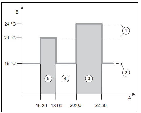
- Time
- Temperature
- Desired temperature
- Set-back temperature
- Time period 2
- Outside of the time periods
- Time period 1
You can divide a day up into several time periods (3) and (5).
Each time period can comprise an individual start time and end time. The time periods must not overlap. You can assign a different desired temperature (1) to each time period.
Example:
- 16:30 to 18:00; 21 °C
- 20:00 to 22:30; 24 °C
The system control regulates the living rooms to the desired temperature within the time periods. In the times outside of the time periods (4), the system control regulates the living rooms to the lower set-back temperature (2) that is set.
What is the effect of the hybrid manager?
The hybrid manager calculates whether the heat pump or the additional boiler covers the heat demand cost-effectively.
The decision-making criteria are the set tariffs in relation to the heat demand.
To ensure that the heat pump and the additional boiler can work effectively, you must enter the tariffs correctly.
See table SETTINGS menu item. Otherwise, increases costs may arise.
Preventing malfunctions
- Do not cover the system control with furniture, curtains or other objects.
- If the system control is installed in the living room, open all of the thermostatic radiator valves in this room fully.
Setting the heat curve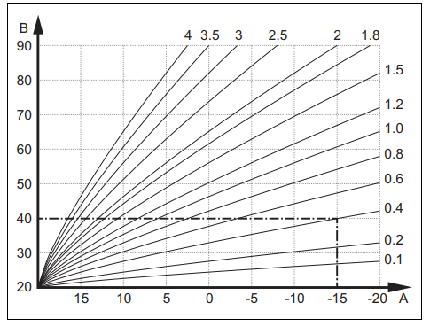
- Outside temperature °C
- Target flow temperature °C
The figure shows the possible heat curves of 0.1 to 4.0 for a target room temperature of 20 °C. If, for example, heat curve 0.4 is selected, a flow temperature of 40 °C is maintained at an outdoor temperature of -15 °C.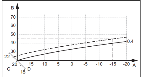
- Outdoor temperature °C
- Target flow temperature °C
- Target room temperature °C
- Axis a
If the heat curve 0.4 is selected and 21 °C is specified for the target room temperature, the heat curve is then translated, as shown in the figure. The heat curve is displaced according to the value of the target room temperature along axis a which is angled at 45°. At an outdoor temperature of -15 °C, the control system provides a flow temperature of 45 °C.
Display, control elements, and symbols

Control elements
 Calling up the menu
- Back to the main menu
 Confirming a selection/change
- Saving set values
- One level back
- canceling input
 Navigating through the menu structure
- Reducing or increasing the set value
- Navigating to individual numbers/letters
 Calling up help
- Calling up the time program assistant
Active control elements light up green.
- Press once: You access the basic display.
- Press twice: You access the menu.
symbols
 Time-controlled heating active
 Button lock active
- Maintenance required
 Fault in the heating installation
 Contact the competent person
 Noise reduction mode active
 Most energy-efficient heating modes active
Operating and display functions
Note
The functions described in this section are not available for all system configurations.
To call up the menu, press![]() twice.
twice.
CONTROL menu item
| MENU → CONTROL | |||
| → Zone | |||
| → Name of zone | Changing the name Zone 1, which was set at the factory | ||
| → Heating → Mode: | → Manual | → Desired temperature: °C | |
| Uninterrupted retention of the desired temperature | |||
| → Time-contr. | → Weekly planner | ||
| → Set-back temperature: °C | |||
| Weekly planner: Up to 12 time periods and desired temperatures can be set per day
The competent person sets how the heating installation behaves outside of the time period in the Set-back mode: function. In Set-back mode: means: – Eco: The heating is switched off outside of the time periods. Frost protection is activated. – Normal: The set-back temperature applies outside of the time periods. Desired temperature: °C: Applies within the time periods |
|||
| → Off | |||
| Heating is switched off, domestic hot water continues to be available, frost protection is activated | |||
| → Cooling → Mode: | → Manual | → Desired temperature: °C | |
| Uninterrupted retention of the desired temperature | |||
| → Time-contr. | → Weekly planner | ||
| → Desired temperature: °C | |||
| Weekly planner: Up to 12 time periods can be set per day; cooling is switched off outside of the time periods
Desired temperature: °C: Applies within the time periods Cooling is switched off outside of the time periods |
|||
| → Off | |||
| Cooling is switched off, domestic hot water remains available | |||
| → Absence | → All: Applies only to any zones within the specified time period | ||
| → Zone: Applies for the selected zone in the specified time period | |||
| Heating and domestic hot water mode is switched off, existing ventilation operates at the lowest ventilation level, frost protection is activated | |||
| → Cooling for several days | Cooling mode is activated in the specified time period, cooling mode and desired temperature are used from the Cooling function | ||
| → Fixed value control, circuit 1 | |||
| → Heating → Mode: | → Manual | ||
| Uninterrupted retention of the Target flow temp., desired: °C that the competent person set. | |||
| → Time-contr. | → Weekly planner | ||
| Weekly planner: Up to 12 time periods can be set per day
Within the time period, the Target flow temp., desired: °C is used. Outside of the time periods, the Target flow temp., set-back: °C is used or the heating circuit is switched off. At a Target flow temp., set-back: °C = 0 °C, the frost protection can no longer be guaranteed. The competent person sets both of these temperatures. |
|||
| → Off | |||
| The heating circuit is switched off. | |||
| → Domestic hot water | |||
| MENU → CONTROL | |||
| → Mode: | → Manual | → DHW temperature | |
| Uninterrupted retention of the domestic hot water temperature | |||
| → Time-contr. | → Domestic hot water weekly planner | ||
| → DHW temperature: °C | |||
| → Circulation weekly planner | |||
| Domestic hot water weekly planner: Up to three time periods can be set per day
DHW temperature: °C: Applies within the time periods Domestic hot water mode is switched off outside of the time periods Circulation weekly planner: Up to three time periods can be set per day The circulation pump pumps hot water to the draw-off points within the time periods Outside of the time periods, the circulation pump is switched off |
|||
| → Off | |||
| Domestic hot water mode is switched off | |||
| → DHW circuit 1 | |||
| → Mode: | → Manual | → DHW temperature: °C | |
| Uninterrupted retention of the domestic hot water temperature | |||
| → Time-contr. | → Domestic hot water weekly planner | ||
| → DHW temperature: °C | |||
| Domestic hot water weekly planner: Up to three time periods can be set per day
DHW temperature: °C: Applies within the time periods Domestic hot water mode is switched off outside of the time periods |
|||
| → Off | |||
| Domestic hot water mode is switched off | |||
| → DHW boost | Heating up the water in the cylinder once | ||
| → Ventilation | |||
| → Mode: | → Normal | → Normal ventilation level: | |
| Uninterrupted ventilation at ventilation level: Normal | |||
| → Time-contr. | → Weekly planner | ||
| → Normal ventilation level: | |||
| → Reduced ventilation level: | |||
| Weekly planner: Up to 12 time periods can be set per day
Normal ventilation level:: Applies within the time periods Reduced ventilation level:: Applies outside of the time periods |
|||
| → Reduced | |||
| Uninterrupted ventilation at ventilation level: Reduced | |||
| → Air quality sensor 1: ppm | Measures the CO2 content of the room air | ||
| → Heat recovery: | → On | ||
| Uninterrupted recovery of the heat from the extract air | |||
| → Auto | |||
| Internal check of whether the outdoor air is guided via the heat recovery or directly into the living room. See the operating instructions for the ventilation unit. | |||
| → Off | |||
| Heat recovery is switched off | |||
| → Air quality limit: ppm | The ventilation unit keeps the CO2 content in the room air below the set value. | ||
| → Ventilation boost | The heating mode is switched off for 30 minutes and, if available, the ventilation unit runs at the highest ventilation level. | ||
| → Humidity prevention | → Max. room air humidity: %rel If the value is exceeded, the dehumidifier switches on. If the value is not reached, the dehumidifier switches off. | ||
| → Time program assistant | Programming of the desired temperature for Monday–Friday and Saturday–Sunday; the programming applies for the time-controlled Heating Cooling, Domestic hot water, Circulation, and Ventilation functions
Overwrites the weekly planner for the Heating, Cooling, Domestic hot water, Circulation and Ventilation functions |
||
| MENU → CONTROL | |
| → Green iQ: | Switching on the most energy-efficient heating mode, if your installation supports this. |
| → Sytem off | Installation is switched off. Frost protection and, if available, ventilation remain activated at the lowest level. |
INFORMATION menu item
| MENU → INFORMATION | ||
| → Current temperatures | ||
| → Zone | ||
| → DHW temperature | ||
| → DHW circuit 1 | ||
| → Water pressure: bar | ||
| → Current room air humidity | ||
| → Energy data | ||
| → Solar yield | ||
| → Environmental yield | ||
| → Power consumption | → Heating | |
| → Domestic hot water | ||
| → Cooling | ||
| → Installation | ||
| → Fuel consumption | → Heating | |
| → Domestic hot water | ||
| → Installation | ||
| → Heat recovery | ||
| Display of energy consumption and energy yield
In the display and in the app that can also be used, the control displays values for the energy consumption and/or the energy yield. The control displays an estimation of the values for the installation. Among other things, the values are influenced by the following: – The installation/design of the heating installation – User behaviour – Seasonal environmental conditions – Tolerances and components External components, such as external heating pumps or valves, and other consumers and appliances in the household are still not taken into consideration. The deviations between the energy consumption or energy yield that is displayed and the actual energy consumption or energy yield may be significant. The specifications for the energy consumption or energy yield are not suitable to be used to create or compare energy billing. The following can be read: Current month, Last month, Current year, Last year, Total |
||
| → Burner status: | ||
| → Control elements | Explanation of the control elements | |
| → Menu introduction | Explanation of the menu structure | |
| → Competent person contact info | ||
| → Serial number | ||
SETTINGS menu item
| MENU → SETTINGS | |||
| → Installer level | |||
| → Enter access code | Access to the installer level, factory setting: 00 | ||
| → Competent person con- tact info | Entering contact details | ||
| → Service date: | Enter the next service date for a connected component, e.g. heat generator, heat pump, ventilation unit | ||
| → Fault history | Faults are listed in chronological order | ||
| → Installation configuration | Functions (→ Installation configuration menu item) | ||
| → Sensor/actuator test | Selecting a connected functional module and
– carrying out a function check of the actuators. – Carry out a plausibility check of the sensors. |
||
| → Noise reduction mode | Set the time programme in order to reduce the noise level. | ||
| → Screed drying | Activate the Screed drying profile function for freshly laid screed in accordance with the construc- tion regulations.
The system control regulates the flow temperature independently of the outdoor temperature. Setting screed drying (→ Installation configuration menu item) |
||
| → Change code | |||
| → Language, time, display | |||
| → Language: | |||
| → Date: | After the power is switched off, the date is retained for approx. 30 minutes. | ||
| → Time: | After the power is switched off, the time is retained for approx. 30 minutes. | ||
| → Display brightness: | |||
| → Daylight saving time: | → Automatic | ||
| → Manual | |||
| For outdoor temperature sensors with DCF77 receivers, the Daylight saving time: function is not used. The conversion to sum- mer/winter time takes place via the DCF77 signal. The change takes place:
– On the last weekend in March at 02:00 (daylight saving time) – On the last weekend in October at 03:00 (standard time) |
|||
| → Tariffs | |||
| → Tariff for back-up boiler: | Enter a gas, oil or electricity tariff | ||
| → Electricity tariff type:
(for heat pump) |
→ Single tariff | → High tariff: | |
| The costs are always calculated using the high tariff. | |||
| → Dual tariff | → Dual tariff weekly planner | ||
| → Low tariff: | |||
| Dual tariff weekly planner: Up to 12 time periods can be set per day
High tariff:: Applies within the time periods Low tariff:: Applies outside of the time periods The costs are calculated using the high and low tariffs. |
|||
| The hybrid manager uses the tariffs and the heat demand to calculate the costs for the back-up boiler and the heat pump. The more cost-effective component is used for the heat generation. | |||
| → Offset | |||
| → Room temperature: K | Comparison of the temperature difference between the measured value in the system control and the value for a reference thermometer in the living room. | ||
| → Outdoor temperature: K | Comparison of the temperature difference between the measured value in the outdoor temperature sensor and the value for a reference thermometer in the living room. | ||
| → Factory settings | The system control resets all of the settings to the factory settings and calls up the installation assist- ant.
Only the competent person can call up the installation assistant. |
||
Installation configuration menu item
| MENU → SETTINGS → Installer level → Installation configuration | |||
| → Installation | |||
| → Water pressure: bar | |||
| → eBUS components | List of eBUS components and their software versions | ||
| → Adaptive heat curve: | Automatic fine adjustment of the heat curve. Prerequisite:
– The suitable heat curve for the building is set in the Heat curve: function. – The correct zone is assigned to the system control or the remote control in the Zone assignment: function. – Expanded is selected in the Room temp. mod.: function. |
||
| → Automatic cooling: | When a heat pump is connected, the system control automatically switches between heating mode and cooling mode. | ||
| → Outdoor temp., 24 hr av.: °C | |||
| → Cooling at outdoor temp.: °C | Cooling starts once the outdoor temperature (24-hour average) exceeds the set temperature. | ||
| → Source regeneration: | The system control switches the Cooling function on and guides the heat from the living room back to the earth via the heat pump. Prerequisite:
– The Automatic cooling: function has been activated. – The Absence function is active. |
||
| → Current room air hum.: %rel | |||
| → Current dew point: °C | |||
| → Hybrid manager: | → triVAl | The heat generator is selected based on the set tariffs in relation to the heat demand. | |
| → Bivalence pt | The heat generator is selected based on the outdoor temperature (
Heating bivalence point: °C and Alternative point). |
||
| → Heating bivalence point: °C | If the outdoor temperature falls below the set value, the system control enables the back-up boiler to operate in parallel with the heat pump in heating mode.
Prerequisite: Bivalence pt is selected in the Hybrid manager: function. |
||
| → DHW bivalence point: °C | If the outdoor temperature falls below the set value, the system control activates the back-up boiler in parallel with the heat pump. | ||
| → Alternative point: | If the outdoor temperature falls below the set value, the system control switches the heat pump off and the back-up boiler meets the heat demand in heating mode.
Prerequisite: Bivalence point is selected in the Hybrid manager: function. |
||
| → LHM temperature: °C | Set a low target flow temperature. If the heat pump fails, the back-up boiler fulfils the heat demand, which leads to higher heating costs. The end user should recognise that heat loss means that there is a problem with the heat pump.
The end user can use the Mode: Temporary back-up boiler mode function to enable the back-up boiler and therefore deactivate the target flow temperature that is set here. |
||
| → Back-up boiler type: | Select a type for the heat generator that is also installed. An incorrect selection may lead to increased costs.
Prerequisite: triVAl is selected in the Hybrid manager: function. |
||
| → ESCO: | Define what you want to deactivate when the signal is sent by the energy supply company. The selection remains deactivated until the energy supply company cancels the signal.
The heat generator ignores the deactivation signal as soon as the frost protection function is active. |
||
| → Back-up boiler: | → Off | The back-up boiler does not support the heat pump.
The back-up boiler is activated for the anti-legionella function, frost pro- tection or de-icing. |
|
| → Heating | The back-up boiler supports the heat pump during heating.
The back-up boiler is activated for the anti-legionella function. |
||
| → DHW | The back-up boiler supports the heat pump during domestic hot water generation.
The back-up boiler is activated for frost protection or de-icing. |
||
| → DHW + heat. | The back-up boiler supports the heat pump during domestic hot water generation and heating. | ||
| → Installation flow temperature: °C | Measured temperature, e.g. downstream of the low loss header | ||
| MENU → SETTINGS → Installer level → Installation configuration | |||
| → Buffer cylinder offset: K | In the case of excessive current, the buffer cylinder is heated up to the flow temperature + set offset via the heat pump. Prerequisite:
– A photovoltaic installation is connected. – Photovoltaics is activated in the HP control module configuration → MI: function. |
||
| → Actuation reversal: | → Off | The system control always actuates the heat generators in the sequence 1, 2, 3, etc. | |
| → On | Once a day, the system control sorts the heat generators based on their actuation time.
The back-up heater is excluded from this sorting. |
||
| Prerequisite: The heating installation contains a cascade. | |||
| → Actuation sequence: | Sequence in which the system control actuates the heat generators.
Prerequisite: The heating installation contains a cascade. |
||
| → Conf. ext. input: | Select whether the external heating circuit is deactivated using a bridge or open terminals.
Prerequisite: The FM5 and/or FM3 functional module is connected. |
||
| → Basic system diagram config. | |||
| → Basic system diagram code: | Systems are roughly grouped according to their connected system components. Each group has a basic system diagram code. Based on the code that is entered, the system control enables the system-related functions.
You can use the connected components to determine the basic system diagram code for the installed installation (→ Using the functional modules, basic system diagram, start-up) and enter this here. |
||
| → FM5 configuration: | Each configuration corresponds to a defined terminal assignment (→ Connection assignment for the FM5 functional module). The terminal assignment determines which functions contain the inputs and outputs.
Select the configuration that suits the installation that is installed. |
||
| → FM3 configuration: | Each configuration corresponds to a defined terminal assignment (→ Connection assignment for the FM3 functional module). The terminal assignment determines which functions contain the inputs and outputs.
Select the configuration that suits the installation that is installed. |
||
| → FM3 MO: | Select the multi-function output’s function assignment. | ||
| → FM5 MO: | Select the multi-function output’s function assignment. | ||
| → HP control module configuration | |||
| → MO 2: | Select the multi-function output’s function assignment. | ||
| → MI: | → Not connec- ted | The system control ignores the signal present. | |
| → 1 x circula- tion | The end user has pressed the circulation button. The system control activates the circulation pump for a short time period. | ||
| → Photovoltaics | In the case of excessive current, a signal is present and the system con- trol activates the DHW boost function once. If the signal persists, the buffer cylinder is charged to the flow temperature + buffer cylinder offset until the signal at the heat pump drops off again. | ||
| The system control queries whether a signal is present at the heat pump’s input. For example:
– aroTHERM input: MI for the heat pump control module – flexoTHERM input: X41, terminal in the functional drawing |
|||
| → Heat generator 1
→ Heat pump 1 → HP control module |
|||
| → Status: | |||
| → Current flow temperature: °C | |||
| → Circuit 1 | |||
| → Circuit type: | → Inactive | The heating circuit is not being used. | |
| → Heating | The heating circuit is being used to heat and is weather-compensated. Depending on the basic system diagram, the heating circuit may be a mixing circuit or a direct circuit. | ||
| → Fixed value | The heating circuit is used for heating and is maintained at a fixed target flow temperature. | ||
| → DHW | The heating circuit is being used as a domestic hot water circuit for an additional cylinder. | ||
| MENU → SETTINGS → Installer level → Installation configuration | |||
| → Circuit type: | → Increase in return | The heating circuit is used to increase the return flow. The increase in return prevents an excessive temperature difference between the heat- ing flow and return, and protects against corrosion in the floor-standing boiler when the dew point is not reached for an extended period. | |
| → Status: | |||
| → Target flow temperature: °C | |||
| → Actual flow temperature: °C | |||
| → Target return temperature: °C | Select a temperature at which the heating water should flow back into the floor-standing boiler. | ||
| → OT switch-off threshold: °C | Enter the upper limit for the outdoor temperature. If the outdoor temperature rises above the set value, the system control deactivates heating mode. | ||
| → Target flow temp., desired: °C | Select the temperature for the fixed value circuit which applies within the time period. | ||
| → Target flow temp., set-back: °C | Select the temperature for the fixed value circuit which applies outside of the time period. | ||
| → Heat curve: | The heat curve (→ section “Product description”) is the dependence of the flow temperature on the outdoor temperature for the desired temperature (target room temperature). | ||
| → Min. target flow temperature:°C | Enter the lower limit for the target flow temperature. The system control compares the set value with the calculated target flow temperature, and regulates to the larger of these values. | ||
| → Max. target flow temperature:°C | Enter the upper limit for the target flow temperature. The system control compares the set value with the calculated target flow temperature, and regulates to the smaller of these val- ues. | ||
| → Set-back mode: | |||
| → Eco | The heating function is switched off and the frost protection function is activated.
At outdoor temperatures that are below 4 °C for longer than four hours, the system control switches the heat generator on and regulates to the Set-back temperature: °C. At an outdoor temperature above 4 °C, the system control switches the heat generator off. The monitoring of the outdoor temperature remains active. Heating circuit behaviour outside of the time periods. Prerequisite: – Time-contr. is activated in the Heating → Mode: function. – Active or Inactive is activated in the Room temp. mod.: function. If Expanded is activated in the Room temp. mod.:, the system control regulates to the target room temperature 5 °C independently of the out- door temperature. |
||
| → Normal | The heating function is switched on. The system control regulates to the
Set-back temperature: °C. Prerequisite: Time-contr. is activated in the Heating → Mode: function. |
||
| The behaviour can be adjusted separately for each heating circuit. | |||
| → Room temp. mod.: | |||
| → Inactive | |||
| → Active | Adjusting the flow temperature based on the current room temperature. | ||
| → Expanded | Adjusting the flow temperature based on the current room temperature. The system control also activates/deactivates the zone.
– The zone is deactivated: Current room temperature + 2/16 K > set room temperature – Zone is activated: Current room temperature < set room temperature – 3/16 K |
||
| The installed temperature sensor measures the current room temperature. The system control calculates a new target room temper- ature that is used to adjust the flow temperature.
– Difference = Set target room temperature – current room temperature – New target room temperature = Set target room temperature + difference Prerequisite: In the Zone assignment: function, the system control and/or the remote control is assigned to the zone in which the system control or remote control is installed. The Room temp. mod.: function is ineffective if No assignmt is activated in the Zone assignment: function. |
|||
| → Cooling possible: | Prerequisite: A heat pump is connected. | ||
| → Dew point monitoring: | The system control compares the set minimum cooling target flow temperature with the cur- rent dew point + set dew point offset. The system control selects the higher temperature for the target flow temperature in order to prevent condensate.
Prerequisite: The Cooling possible: function has been activated. |
||
| MENU → SETTINGS → Installer level → Installation configuration | ||
| → Min. cooling targ. flow temp.: °C | The system control regulates the heating circuit to the Min. cooling targ. flow temp.: °C.
Prerequisite: The Cooling possible: function has been activated. |
|
| → Dew point offset: K | Safety margin that is added to the current dew point. Prerequisite:
– The Cooling possible: function has been activated. – The Dew point monitoring: function has been activated. |
|
| → Ext. heat demand: | Display showing whether a heat demand is present at an external input.
When installing an FM5 or FM3 functional module, external inputs are available, depending on the configuration. You can connect an external zone controller, for example, to this ex- ternal input. |
|
| → DHW temperature: °C | Desired temperature at the withdrawal point. The heating circuit is used as a domestic hot water circuit. | |
| → Actual cylinder temperature: °C | The heating circuit is used as a domestic hot water circuit. | |
| → Pump status: | ||
| → Mixing valve status: % | ||
| → Zone | ||
| → Zone activated: | Deactivate zones that are not required. All existing zones appear in the display. Prerequisite: The existing heating circuits are activated in the Circuit type: function. | |
| → Zone assignment: | Assign the system control and/or remote control to the selected zone. The system control and/or remote control must be installed in the selected zone. The control system also uses the room temperature sensor for the assigned unit. The remote control uses all of the val- ues for the assigned zone. The Room temp. mod.: function is ineffective if you have not as- signed any zones. | |
| → Zone valve status: | ||
| → Domestic hot water | ||
| → Cylinder: | If there is an existing domestic hot water cylinder, the Active setting must be selected. | |
| → Target flow temperature: °C | ||
| → Cylinder charging pump: | ||
| → Circulation pump: | ||
| → Anti-legio. day: | Define the days on which you want the anti-legionella function to run. On these days, the water temperature is increased to above 60 °C. The circulation pump is activated. The function ends after 120 minutes at the latest.
If the Absence function is activated, the anti-legionella function is not carried out. As soon as the Absence function ends, the anti-legionella function is carried out. Heating installations with heat pumps use the backup boiler for legionella protection. |
|
| → Anti-legio. time: | Define the time at which you want the anti-legionella function to run. | |
| → Cylinder charging hysteresis: K | The cylinder charging starts as soon as cylinder temperature < desired temperature – hysteresis
value. |
|
| → Cylinder charging offset: K | Desired temperature + offset = flow temperature for the domestic hot water cylinder. | |
| → Max. cyl. charging time: | Setting the maximum time at which the domestic hot water cylinder can be charged without interruption. If the maximum time or the target temperature is reached, the system control enables the heating function. The setting Off means that the cylinder charging time is not restricted. | |
| → Cyl. charge. anti-cycle. time: min | Setting the time period during which the cylinder charging is blocked after the maximum cylinder charging time has elapsed. During the blocked time, the system control enables the heating function. | |
| → Parallel cylinder charging: | When charging the domestic hot water cylinder, the mixing circuit is heated in parallel. The non-mixed heating circuit is always switched off during cylinder charging. | |
| → Buffer cylinder | ||
| → Cylinder temp., top: °C | Actual temperature in the upper section of the buffer cylinder | |
| → Cylinder temp., bottom: °C | Actual temperature in the lower section of the buffer cylinder | |
| → DHW temp. sensor, top: °C | Actual temperature in the upper part of the domestic hot water section of the buffer cylinder | |
| → DHW temp. sensor, bottom: °C | Actual temperature in the lower part of the domestic hot water section of the buffer cylinder | |
| → Heat. temp. sensor, top: °C | Actual temperature in the upper part of the heating section of the buffer cylinder | |
| → Heat. temp. sensor, bottom: °C | Actual temperature in the lower part of the heating section of the buffer cylinder | |
| → Solar cylinder, bottom: °C | Actual temperature in the lower section of the solar cylinder | |
| MENU → SETTINGS → Installer level → Installation configuration | ||
| → Max. DHW targ. flow temp..: °C | Setting the maximum buffer cylinder target flow temperature for the domestic hot water station. The set maximum target flow temperature must be lower than the maximum flow temperature for the heat generator.
If the maximum target flow temperature is set too low, the domestic hot water station cannot reach the target cylinder temperature. While the target cylinder temperature is not reached, the system control does not enable the heat generator for heating mode. You can find the maximum flow temperature in the installation instructions for the heat generator. |
|
| → Max. temp. of cylinder 1: °C | Setting the maximum cylinder temperature. The solar circuit stops the cylinder charging as soon as the maximum cylinder temperature has been reached. | |
| → Solar circuit | ||
| → Collector temperature: °C | ||
| → Solar pump: | ||
| → Solar yield sensor: °C | ||
| → Solar flow rate quantity: | Entering the volume flow to calculate the solar yield. If a solar pump station is installed, the system control ignores the value that has been entered and uses the volume flow that is supplied from the solar pump station.
The value 0 means the automatic recording of the volume flow. |
|
| → Solar pump kick: | Accelerated recording of the collector temperature. When the function is activated, the solar pump is switched on for a short time and the heated solar fluid is transported to the measuring point more quickly. | |
| → Solar circuit prot. function: °C | Setting the maximum temperature that must not be exceeded in the solar circuit. If the maximum temperature at the collector sensor is exceeded, the solar pump switches off to protect the solar circuit against overheating. | |
| → Min. collector temperature: °C | Setting the minimum collector temperature that is required for the solar charging switch-on differential. The differential temperature control can only start once the minimum collector temperature has been reached. | |
| → Purging time: min | Setting the time period during which the solar circuit is purged. The system control stops the function once the specified purging time has elapsed, the solar circuit protection function is active or the max. cylinder temperature has been exceeded. | |
| → Current flow rate: l/min | Current volume flow of the solar pump station | |
| → Solar cylinder 1 | ||
| → Switch-on differential: K | Setting the differential value for starting the solar charging.
If the temperature difference between the cylinder temperature sensor at the bottom and the collector temperature sensor is greater than the set differential value and the set minimum collector temperature, the cylinder charging is started. The differential value can be defined separately for two connected solar cylinders. |
|
| → Switch-off differential: K | Setting the differential value for stopping the solar charging.
If the temperature difference between the bottom cylinder temperature sensor and the collector temperature sensor is smaller than the set differential value and the set minimum col- lector temperature, the cylinder charging is stopped. The switch-off differential temperature value must be at least 1 K less than the set switch-on differential temperature value. |
|
| → Maximum temperature: °C | Set the maximum cylinder charging temperature for cylinder protection.
If the temperature at the bottom cylinder temperature sensor is higher than the set maximum cylinder charging temperature, the solar charging is interrupted. The solar charging is only enabled again once the temperature at the bottom cylinder temperature sensor has fallen by between 1.5 K and 9 K, depending on the maximum temperature. The set maximum temperature must not exceed the maximum permissible cylinder temperature of the cylinder. |
|
| → Solar cylinder, bottom: °C | ||
| → 2nd diff. temp control | ||
| → Switch-on differential: K | Setting the differential value for starting the temperature difference control, such as solar heating support.
If the temperature difference between different temperature sensor 1 and differential temperature sensor 2 is greater than the set switch-on differential and the set minimum temperature at differential temperature sensor 1, the differential temperature control is started. |
|
| → Switch-off differential: K | Setting the differential value for stopping the temperature difference control, such as solar heating support.
If the temperature difference between different temperature sensor 1 and differential temperature sensor 2 is lower than the set switch-off differential and the set maximum temperature at differential temperature sensor 2, the differential temperature control is stopped. |
|
| → Minimum temperature: °C | Setting the minimum temperature for starting the differential temperature control. | |
| MENU → SETTINGS → Installer level → Installation configuration | ||
| → Maximum temperature: °C | Setting the maximum temperature for stopping the differential temperature control. | |
| → Diff. temp. sensor 1: | ||
| → Diff. temp. sensor 2: | ||
| → Diff. temp. sensor output: | ||
| → Screed drying profile | Setting target flow temperature per day in accordance with the construction regulations | |
Electrical installation, set-up
Only qualified electricians may carry out the electrical installation.
The heating installation must be decommissioned before work is carried out on it.
Selecting the lines
- Do not use flexible lines for power supply cables.
- Use sheathed cables for power supply cables (e.g. NYM 3 x 1.5).
Line cross-section
| eBUS line (extra-low voltage) | ≥ 0.75 mm² |
| Sensor line (extra low voltage) | ≥ 0.75 mm² |
Line length
| Sensor lines | ≤ 50 m |
| Bus lines | ≤ 125 m |
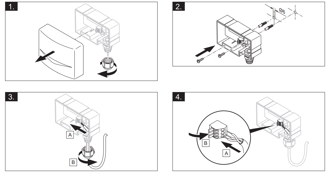
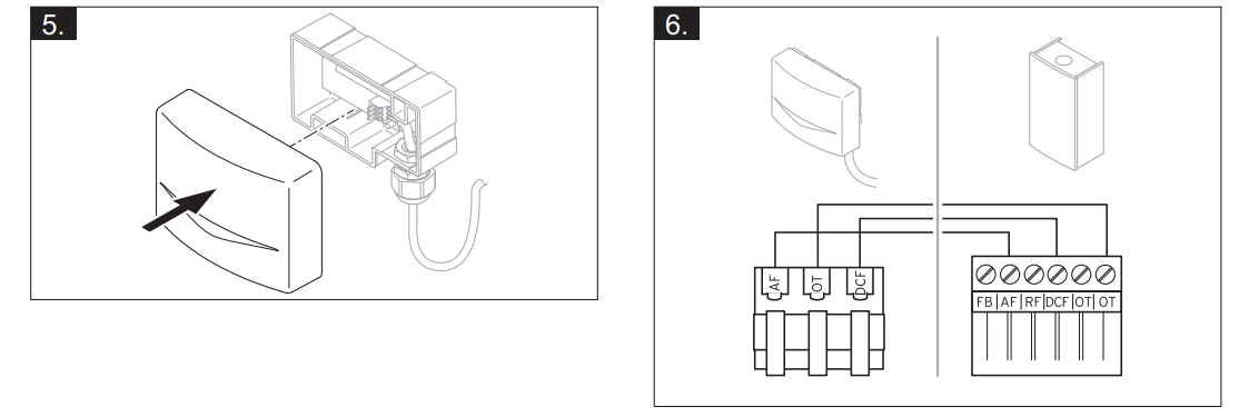
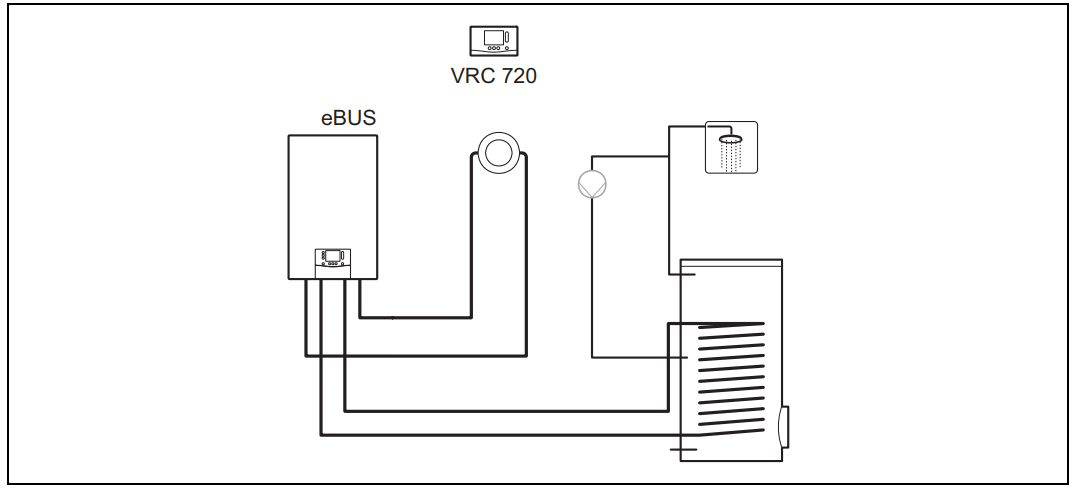
Connecting a system control to the ventilation unit
Connect the system control to the ventilation unit as described in the installation instructions for the ventilation unit.
Condition: Ventilation unit connected to the eBUS without VR 32, Ventilation unit without eBUS heat generator
- Connect the eBUS line to the eBUS terminals in the system control’s wall base.
- Connect the eBUS line to the eBUS terminals on the ventilation unit.
Condition: Ventilation unit connected to the eBUS with VR 32, Ventilation unit with up to two eBUS heat generators
- Connect the eBUS line to the eBUS terminals in the system control’s wall base.
- Connect the eBUS line to the eBUS of the heat generator.
- Set the address switch for the VR 32 in the ventilation unit to position 3.
Condition: Ventilation unit connected to the eBUS with VR 32, Ventilation unit with more than two eBUS heat generators
- Connect the eBUS line to the eBUS terminals in the system control’s wall base.
- Connect the eBUS line to the common eBUS on the heat generator.
- Determine the highest possible position on the address switches of the VR 32 for the connected heat generator.
- Set the address switch of the VR 32 in the ventilation unit to the second-highest position.
Installing the system control and outdoor temperature sensor

Using the functional modules, basic system diagram, start-up
A system without functional modules
Simple systems with a direct heating circuit do not require a functional module.
System with FM3 functional module

Systems with two heating circuits that must be controlled separately from each other require the FM3 functional module.
The VR 92 remote control cannot be added to the system.
A system with FM5 and FM3 functional modules

Systems with more than two mixed heating circuits require the FM5 functional module.
The system may comprise the following:
- Maximum 1 x FM5 functional module
- Maximum 3 x FM3 functional modules, in addition to the FM5 functional module
- Maximum 4 x VR 92 remote controls, which can be installed in each heating circuit
- Maximum 9 x heating circuits, which you achieve using 1 x FM5 functional module and 3 x FM3 functional modules
A potential application for the functional modules
FM5 functional module
Each configuration corresponds to a defined connection assignment of the FM5 functional module.
| Configure- option | System property | Mixed heating circuits |
| 1 | Solar heating and/or domestic hot water support with two solar cylinders | Max. 2 |
| 2 | Solar heating and/or domestic hot water support with one solar cylinder | Max. 3 |
| 3 | 3 x mixed heating circuits | Max. 3 |
| 6 | Allstar multi-functional buffer cylinder and domestic hot water station | Max. 3 |
FM3 functional module
If an FM3 functional module is installed, the system has one mixed and one non-mixed heating circuit.
The potential configuration (FM3) corresponds to a defined terminal assignment for the FM3 functional module.
FM3 and FM5 functional modules
If the FM3 and FM5 functional modules are installed in a system, each additional installed FM3 functional module adds two mixed heating circuits to the system.
The potential configuration (FM3+FM5) corresponds to a defined terminal assignment for the FM3 functional module.
Terminal assignment for the FM5 functional module
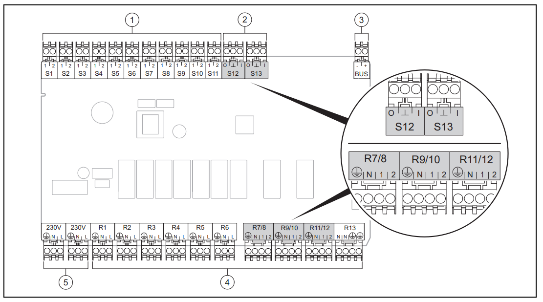
- Input sensor terminals
- Signal terminals
- eBUS terminal
When connecting, pay attention to the polarity! - Output relay terminals
- Power supply
S6 to S11 sensor terminals: An external control can also be connected
S12, S13 signal terminals: I = input, O = output
R7/8, R9/10, R11/12 mixer output: 1 = open, 2 = closed
You can configure the contacts for external inputs in the system control.
- Open, deactivate.: Contacts open, no heat demand
- Bridge, deactivate.: Contacts closed, no heat demand
| Configur- ation | R1 | R2 | R3 | R4 | R5 | R6 | R7/R8 | R9/R10 | R11/R12 | R13 |
| 1 | 3f1 | 3f2 | 9gSolar | MA | 3j | 3c/9e | 9k1op/ 9k1cl | 9k2op/ 9k2cl | – | – |
| 2 | 3f1 | 3f2 | 3f3 | MA | 3j | 3c/9e | 9k1op/ 9k1cl | 9k2op/ 9k2cl | 9k3op/ 9k3cl | – |
| 3 | 3f1 | 3f2 | 3f3 | MA | – | 3c/9e | 9k1op/ 9k1cl | 9k2op/ 9k2cl | 9k3op/ 9k3cl | – |
| 6 | 3f1 | 3f2 | 3f3 | MA | 9gSolar | 3c/9e | 9k1op/ 9k1cl | 9k2op/ 9k2cl | 9k3op/ 9k3cl | – |
| Configur- ation | S1 | S2 | S3 | S4 | S5 | S6 | S7 | S8 | S9 | S10 | S11 | S12 | S13 |
| 1 | SysFlow | FS1 | FS2 | DHW
Bt2 |
DHW | DHWBt | COL | Solar yield | DEM2 | TD1 | TD2 | PWM | – |
| 2 | SysFlow | FS1 | FS2 | FS3 | DHW | DHWBt | COL | Solar yield | – | TD1 | TD2 | PWM | – |
| Configur-ation | S1 | S2 | S3 | S4 | S5 | S6 | S7 | S8 | S9 | S10 | S11 | S12 | S13 |
| 3 | SysFlow | FS1 | FS2 | FS3 | BufBt | DEM1 | DEM2 | DEM3 | DHW | – | – | – | – |
| 6 | SysFlow | FS1 | FS2 | FS3 | BufBt | BufBtCH | BufTop DHW | BufBt DHW | DEM1 | DEM2 | DEM3 | – | – |
Sensor assignment
| Configuration | S1 | S2 | S3 | S4 | S5 | S6 | S7 | S8 | S9 | S10 | S11 | S12 | S13 |
| 1 | VR 10 | VR 10 | VR 10 | VR 10 | VR 10 | VR 10 | VR 11 | VR 10 | – | VR 10 | VR 10 | – | – |
| 2 | VR 10 | VR 10 | VR 10 | VR 10 | VR 10 | VR 10 | VR 11 | VR 10 | – | VR 10 | VR 10 | – | – |
| 3 | VR 10 | VR 10 | VR 10 | VR 10 | VR 10 | – | – | – | VR 10 | VR 10 | – | – | – |
| 6 | VR 10 | VR 10 | VR 10 | VR 10 | VR 10 | VR 10 | VR 10 | VR 10 | – | – | – | VR 10 | – |
Terminal assignment for the FM3 functional module

- Input sensor terminals
- signal terminal
- Address switch
- eBUS terminal
- Mixer output
- Output relay terminals
- Power supply
S2, S3 sensor terminals: An external control can also be connected
R3/4, R5/6 mixer output: 1 = open, 2 = closed
You can configure the contacts for external inputs in the system control.
- Open, deactiv.: Contacts open, no heat demand
- Bridge, deactiv.: Contacts closed, no heat demand
| Configuration | R1 | R2 | R3/R4 | R5/R6 | S1 | S2 | S3 | S4 | S5 | S6 | S7 |
| FM3+FM5 | 3fa | 3fb | 9kaop/ 9kacl | 9kbop/ 9kbcl | – | DEMa | DEMb | – | FSa | FSb | – |
| FM3 | 3f1 | 3f2 | MA | 9k2op/ 9k2cl | BufBt/ DHW | DEM1 | DEM2 | – | SysFlow | FS2 | – |
Sensor assignment
| Configuration | S1 | S2 | S3 | S4 | S5 | S6 | S7 |
| FM3+FM5 | – | – | – | – | VR 10 | VR 10 | – |
| FM3 | VR 10 | – | – | – | VR 10 | VR 10 | – |
Settings for the basic system diagram codes
The systems are roughly grouped according to their connected system components. Each grouping contains a basic system diagram code that you must enter in the Basic system diagram code: function in the system control. The system control requires the basic system diagram code in order to enable the system-related functions.
Gas- or oil-fired boiler as a single unit
| System property | Basic system diagram code: |
| Allstar cylinder system incl. domestic hot water station | 1 |
| Boilers with solar domestic hot water support | 1 |
| All boilers without solar
– Connecting the domestic hot water cylinder temperature sensor to the boiler |
1 |
| Exceptions: | |
| Boilers without solar
– Connecting the domestic hot water cylinder temperature sensor to the functional module |
1)
2 |
| Boiler with solar heating and hot water support | 1)
2 |
| 1) Do not use the integrated prioritizing diverter valve from the Ecotec VC boiler (permanent position: Heating mode). | |
Cascade with gas- or oil-fired boilers
Maximum seven boilers possible
As for the second boiler, the boilers are connected via VR 32 (addresses 2 to 7).
| System property | Basic sys- tem dia- gram code: |
| Domestic hot water generation is provided by a selected boiler (isolating circuit)
– Domestic hot water generation provided by the boiler with the highest address – Connecting a domestic hot water cylinder temperature sensor to this boiler |
1 |
| Domestic hot water generation provided by the whole cascade (no isolating circuit)
– Connecting the domestic hot water cylinder temperature sensor to the FM5 functional module |
1)
2 |
| Allstar cylinder system incl. domestic hot water station | 1)
2 |
| 1) Do not use the integrated prioritizing diverter valve from the Ecotec VC boiler (permanent position: Heating mode). | |
Heat pump as a single unit (monoenergetic)
With an immersion heater in the flow as a back-up boiler
| System property | Basic system diagram code: | |
| Without heat ex-
1) changer |
With heat
1) exchanger |
|
| Without solar
– Connecting the domestic hot water cylinder temperature sensor to the heat pump control module and/or heat pump |
8 | 11 |
| With solar domestic hot water support | 8 | 11 |
| allSTOR cylinder system incl. domestic hot water station | 8 | 16 |
| 1) E.g. VWZ MWT | ||
Heat pump as a single unit (hybrid)
With an external backup boiler
A backup boiler (with eBUS) is connected via the VR 32 (address 2).
A backup boiler (without eBUS) is connected to the output for the heat pump or the heat pump control module for the external back-up boiler.
| System property | Basic system diagram code: | |
| Without heat ex-
1) changer |
With heat
1) exchanger |
|
| Domestic hot water generation only provided by the back-up boiler without the functional module
– Connecting the domestic hot water cylinder temperature sensor to a back-up boiler (separate charge control) |
8 | 10 |
| Domestic hot water generation is only provided by the backup boiler with the functional module
– Connecting the domestic hot water cylinder temperature sensor to a backup boiler (separate charge control) |
9 | 10 |
| Domestic hot water generation through the heat pump and backup boiler
– Connecting the domestic hot water cylinder temperature sensor to the FM5 functional module – Without the FM5 functional module, connecting the domestic hot water cylinder temperature sensor to the heat pump control module and/or heat pump |
16 | 16 |
| Domestic hot water generation is provided by the heat pump and backup boiler with a bivalent domestic hot water cylinder
– Connecting the upper domestic hot water cylinder temperature sensor to a backup boiler (separate charge control) – Connecting the lower domestic hot water cylinder temperature sensor to the heat pump control module and/or heat pump |
12 | 13 |
| 1) E.g. VWZ MWT | ||
Cascade with heat pumps
Maximum seven heat pumps possible
With an external back-up boiler
As for the second heat pump, the heat pumps and, if required, the heat pump control modules, are connected via the VR 32 (B) (address 2 to 7).
A backup boiler (with eBUS) is connected via the VR 32 (next free address).
A backup boiler (without eBUS) is connected to the output for the first heat pump or the heat pump control module for the
external backup boiler.
| System property | Basic system diagram code: | |
| Without heat ex-
1) changer |
With heat
1) exchanger |
|
| Domestic hot water generation is provided by the backup boiler only
– Connecting the domestic hot water cylinder temperature sensor to a backup boiler (separate charge control) |
9 | – |
| Domestic hot water generation through the heat pump and backup boiler
– Connecting the domestic hot water cylinder temperature sensor to the FM5 functional module |
16 | 16 |
| 1) E.g. VWZ MWT | ||
Combinations of a basic system diagram and configuration of functional modules
You can use the table to check the selected combination of the basic system diagram code and the configuration of functional modules.
| Basic system diagram code: | System | Without FM5,
without FM3 |
With FM3 | With FM5 | With FM5
+ Max. 3 x FM3 |
|||||
| Configuration | ||||||||||
| 1 | 2 | 1 | 2 | 3 | 6 | |||||
| Solar domestic hot water gener- ation | Solar heating support | |||||||||
| For conventional heat generators | ||||||||||
| 1 | Gas-/oil-fired boiler | x | 1)
x |
x | x | – | – | 1)
x |
1)
x |
x |
| Gas-/oil-fired boiler, cascade | – | – | – | – | – | – | 1)
x |
– | x | |
| 2 | Gas-/oil-fired boiler | – | 1)
x |
– | – | x | x | 1)
x |
– | x |
| Gas-/oil-fired boiler, cascade | – | – | – | – | – | – | 1)
x |
1)
x |
x | |
| For heat pump systems | ||||||||||
| 8 | Monoenergetic heat pump sys- tem | x | 1)
x |
x | x | – | – | 1)
x |
1)
x |
x |
| Hybrid system | x | – | – | – | – | – | – | – | – | |
| 9 | Hybrid system | – | 1)
x |
– | – | – | – | 1)
x |
– | x |
| Cascade of heat pumps | – | – | – | – | – | – | 1)
x |
– | x | |
| 10 | Mono-energy heat pump sys-
2) tem with heat exchanger |
x | 1)
x |
– | – | – | – | 1)
x |
– | x |
| Hybrid system with heat ex-
2) changer |
x | 1)
x |
– | – | – | – | 1)
x |
– | x | |
| 11 | Mono-energy heat pump sys-
2) tem with heat exchanger |
x | 1)
x |
x | x | – | – | 1)
x |
– | x |
| 12 | Hybrid system | x | 1)
x |
– | – | – | – | 1)
x |
– | x |
| 13 | Hybrid system with heat ex-
2) changer |
– | 1)
x |
– | – | – | – | 1)
x |
– | x |
| 16 | Hybrid system with heat ex-
2) changer |
– | 1)
x |
– | – | – | – | 1)
x |
1)
x |
x |
| Cascade of heat pumps | – | – | – | – | – | – | 1)
x |
1)
x |
x | |
| Mono-energy heat pump sys-
2) tem with heat exchanger |
x | 1)
x |
– | – | – | – | 1)
x |
1)
x |
x | |
| x: Combination possible
–: Combination not possible 1) Buffer management possible 2) E.g. VWZ MWT |
||||||||||
Basic system diagram and wiring diagram
Meaning of the abbreviations
| Abbreviation | Meaning |
| 1 | Heat generator |
| 1a | Domestic hot water back-up boiler |
| 1b | Heating back-up boiler |
| 1c | Domestic hot water/heating back-up boiler |
| 1d | Solid fuel boiler with manual feed |
| 2 | Heat pump |
| 2a | Air-to-water heat pump |
| 2b | Air-to-brine heat exchanger |
| 2c | Refrigerant-split heat pump outdoor unit |
| 2d | Refrigerant-split heat pump indoor unit |
| 2e | Ground water module |
| 2f | Passive cooling module |
| 3 | Heat generator circulation pump |
| 3a | Swimming pool circulation pump |
| 3b | Cooling circuit pump |
| 3c | Cylinder charging pump |
| 3d | Well pump |
| 3e | Circulation pump |
| 3f[x] | Heating pump |
| 3g | Heat source circulation pump |
| 3h | Anti-legionella pump |
| 3i | Pump heat exchanger |
| 3j | Solar pump |
| 4 | Buffer cylinder |
| 5 | Monovalent domestic hot water cylinder |
| 5a | Bivalent domestic hot water cylinder |
| 5b | Shift-load cylinder |
| 5c | Combi cylinder |
| 5d | Multi-functional buffer cylinder |
| 5e | Hydraulic tower |
| 6 | Solar collector (thermal) |
| 7a | Heat pump brine filling unit |
| 7b | Solar pump station |
| 7c | Domestic hot water station |
| 7d | Heat interface unit |
| 7e | Hydraulic block |
| 7f | Decoupler module |
| 7g | Heat recovery module |
| 7h | Heat exchanger module |
| 7i | 2-zone module |
| 7j | Pump group |
| 8a | Expansion relief valve |
| 8b | Potable water expansion relief valve |
| 8c | Safety assembly – potable water connection |
| 8d | Safety assembly for the heat generator |
| 8e | Heating diaphragm expansion vessel |
| Abbreviation | Meaning |
| 8f | Diaphragm expansion vessel – potable water |
| 8g | Solar/brine diaphragm expansion vessel |
| 8h | Solar protection vessel |
| 8i | Thermal safety assembly |
| 9a | Single-room temperature control valve (ther- mostatic/motorised) |
| 9b | Zone valve |
| 9c | Flow regulator valve |
| 9d | Bypass valve |
| 9f | Diverter valve, cooling |
| 9e | Diverter valve for potable water |
| 9g | Diverter valve |
| 9gSolar | Solar diverter valve |
| 9h | Filling/draining cock |
| 9i | Purging valve |
| 9j | Tamper-proof capped valve |
| 9k[x] | 3-port mixing valve |
| 9l | Cooling 3-port mixing valve |
| 9m | Increase in return for 3-port mixing valve |
| 9n | Thermostatic mixing valve |
| 9o | Flow meter (TacoSetter) |
| 9p | Cascade valve |
| 10a | Thermometer |
| 10b | Manometer |
| 10c | Non-return valve |
| 10d | Air separator |
| 10e | Line strainer with magnetite separator |
| 10f | Solar/brine collecting vessel |
| 10g | Heat exchanger |
| 10h | Low loss header |
| 10i | Flexible connections |
| 11a | Fan coil |
| 11b | Swimming pool |
| 12 | System control |
| 12a | Remote control |
| 12b | Heat pump control module |
| 12c | 2 in 7 multi-functional module |
| 12d | FM3 functional module |
| 12e | FM5 functional module |
| 12f | Wiring centre |
| 12g | eBUS bus coupler |
| 12h | Solar control |
| 12i | External control |
| 12j | Cut-off relay |
| 12k | Limit thermostat |
| 12l | Cylinder temperature cut-out |
| 12m | Outdoor temperature sensor |
| 12n | Flow switch |
| 12o | eBUS power supply unit |
| Abbreviation | Meaning |
| 12p | Radio receiver unit |
| 12q | Internet gateway |
| 13 | Ventilation unit |
| 14a | Supply air outlet |
| 14b | Extract air inlet |
| 14c | Air filter |
| 14d | Reheater |
| 14e | Frost protection element |
| 14f | Silencer |
| 14g | Restrictor flap |
| 14h | Weather guard grille |
| 14i | Extract air box |
| 14j | Air humidifier |
| 14k | Air dehumidifier |
| 14l | Air manifold |
| 14m | Air collector |
| 15 | Cylinder ventilation unit |
| BufBt | Bottom buffer cylinder temperature sensor |
| BufBtCH | Bottom temperature sensor for heating sec- tion of buffer cylinder |
| BufTopCH | Top temperature sensor for heating section of buffer cylinder |
| BufBtDHW | Bottom temperature sensor for DHW section of buffer cylinder |
| BufTopDHW | Top temperature sensor for DHW section of buffer cylinder |
| C1/C2 | Enable cylinder charging/buffer cylinder charging |
| COL | Collector temperature sensor |
| DEM[x] | External heat demand for the heating circuit |
| DHW | Cylinder temperature sensor |
| DHWBt | Bottom cylinder temperature sensor (do- mestic hot water cylinder) |
| DHWBt2 | Cylinder temperature sensor (second solar cylinder) |
| EVU | Energy supply company switching contact |
| FS[x] | Flow temperature sensor for heating cir- cuit/swimming pool sensor |
| MA | Multi-function output |
| ME | Multi-function input |
| PV | Photovoltaic inverter interface |
| PWM | PWM signal for pump |
| RT | Room thermostat |
| SCA | Cooling signal |
| SG | Transmission system operator interface |
| Solar yield | Solar yield sensor |
| SysFlow | System temperature sensor |
| TD1, TD2 | Temperature sensor for a differential temper- ature control |
| TEL | Switch contact for remote control |
| TR | Isolating circuit with switching floor-standing boiler |
Basic system diagram 0020184677
Setting on the system control
Basic system diagram code: 1
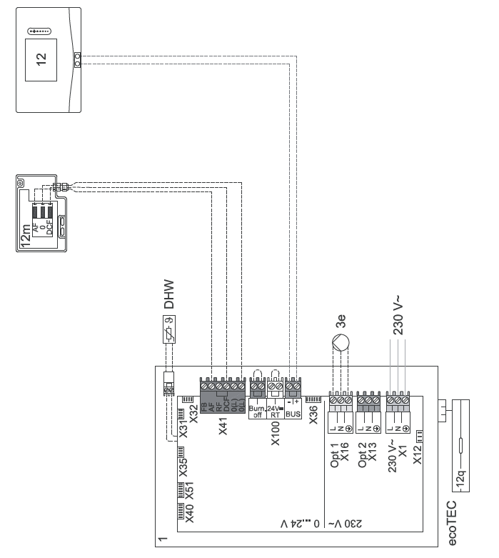
Basic system diagram 0020184677
 wiring diagram 0020184677
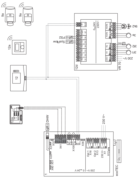
 Basic system diagram 0020284121
Settings on the system control
- Basic system diagram code: 1
- FM3 configuration: 1
- FM3 MO: Circulation pump
- Circuit 1 / Circuit type: Heating
- Circuit 1 / Room temp. mod.: Inactive
- Circuit 2 / Circuit type: Heating
- Circuit 2 / Room temp. mod.: Active or Expanded
- Zone 1/ Zone activated: Yes
- Zone 1 / Zone assignment: No assignmt
- Zone 2/ Zone activated: Yes
- Zone 2 / Zone assignment: Control
Basic system diagram 0020284121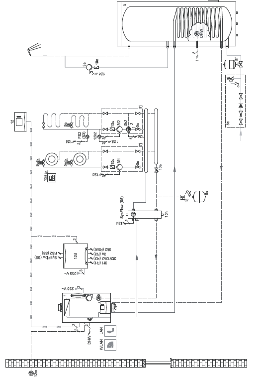
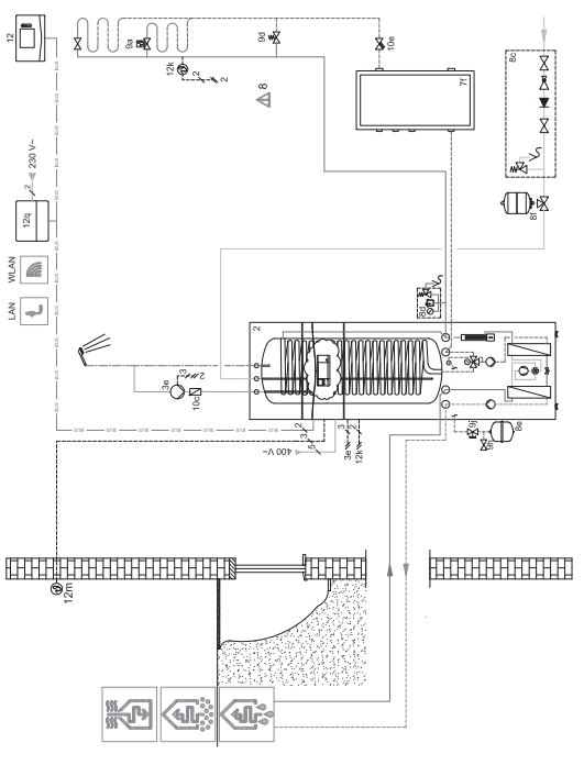
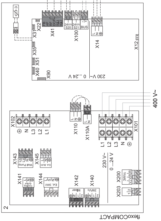
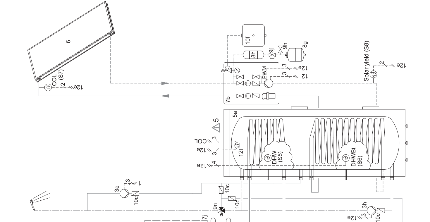
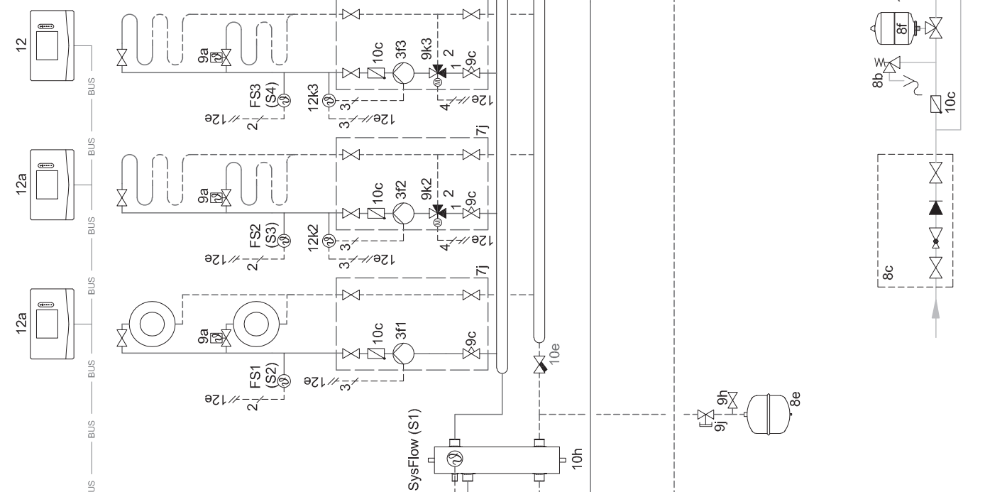
Basic system diagram 0020177912
Special features of the system
8: At least 35% of the nominal flow rate must always be able to flow through a reference room without an individual
room temperature control valve.
Settings on the system control
- Basic system diagram code: 8
- Circuit 1 / Room temp. mod.: Active or Expanded
- Zone 1 / Zone assignment: Control
Settings in the heat pump
Cooling technology: No cooling
Basic system diagram 0020177912
 Wiring diagram 0020177912
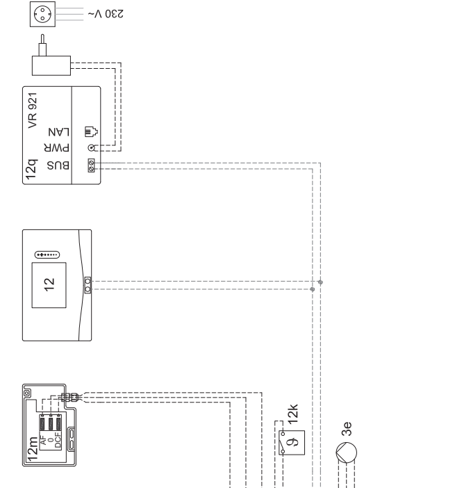
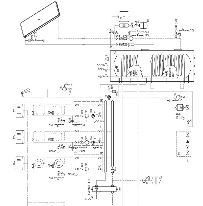
Basic system diagram 0020280010
Special features of the system
5: The cylinder temperature cut-out must be installed in a suitable location in order to avoid cylinder temperatures above 100 °C.
Settings on the system control
- Basic system diagram code: 1
- FM5 configuration: 2
- FM5 MO: Anti-legio. pump
- Circuit 1 / Circuit type: Heating
- Circuit 1 / Room temp. mod.: Active or Expanded
- Circuit 2 / Circuit type: Heating
- Circuit 2 / Room temp. mod.: Active or Expanded
- Circuit 3 / Circuit type: Heating
- Circuit 3 / Room temp. mod.: Active or Expanded
- Zone 1/ Zone activated: Yes
- Zone 1 / Zone assignment: Rem. contr. 1
- Zone 2/ Zone activated: Yes
- Zone 2 / Zone assignment: Rem. contr. 2
- Zone 3/ Zone activated: Yes
- Zone 3 / Zone assignment: Control
- 4.9.5.3 Settings at the remote control
- Remote control address: (1): 1
- Remote control address: (2): 2
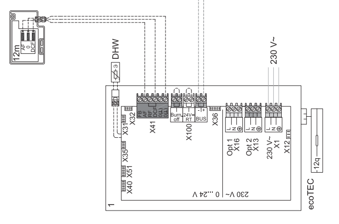
Basic system diagram 0020280010
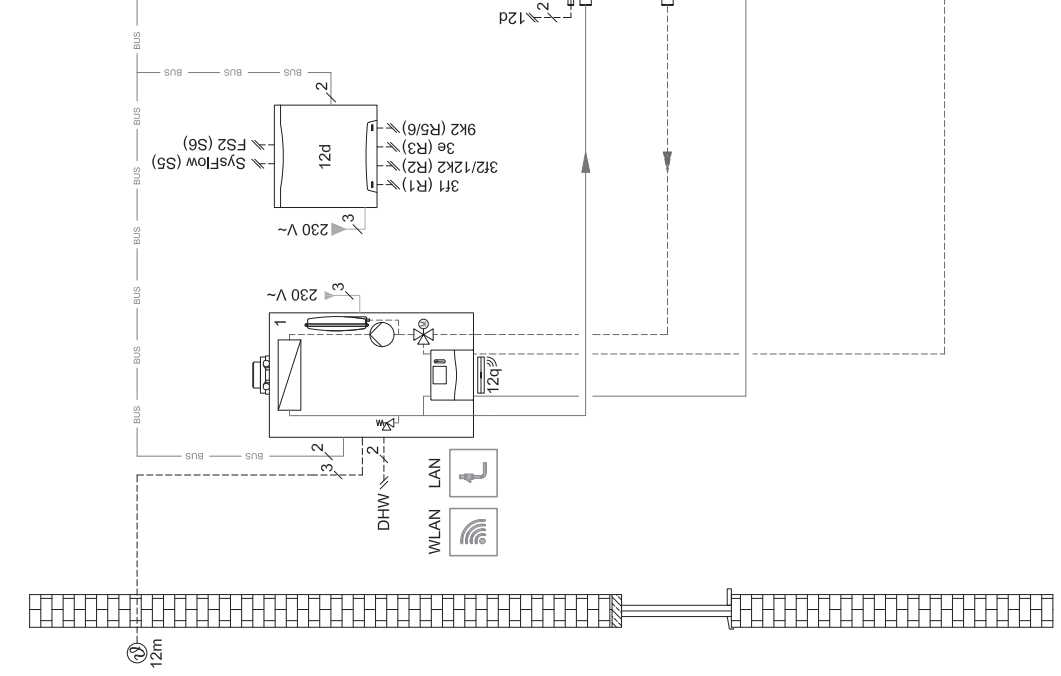
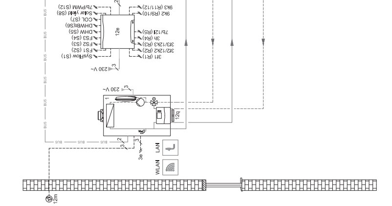
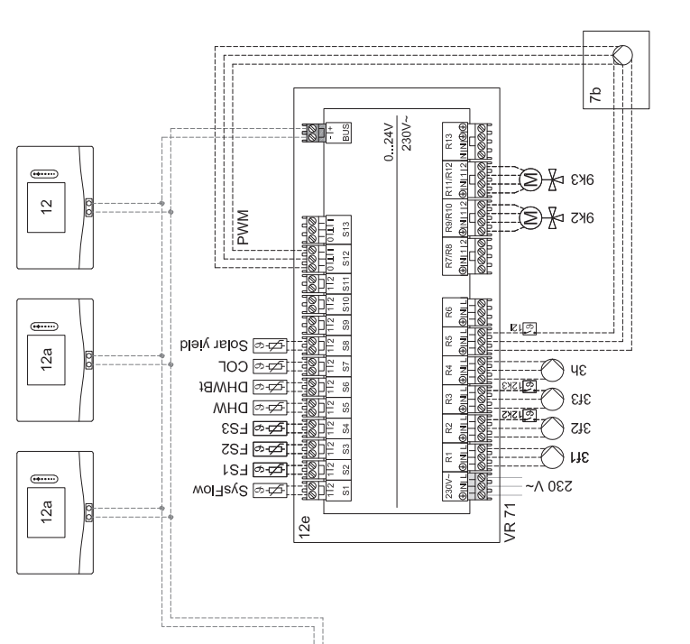
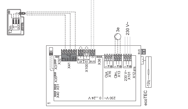
Wiring diagram 0020280010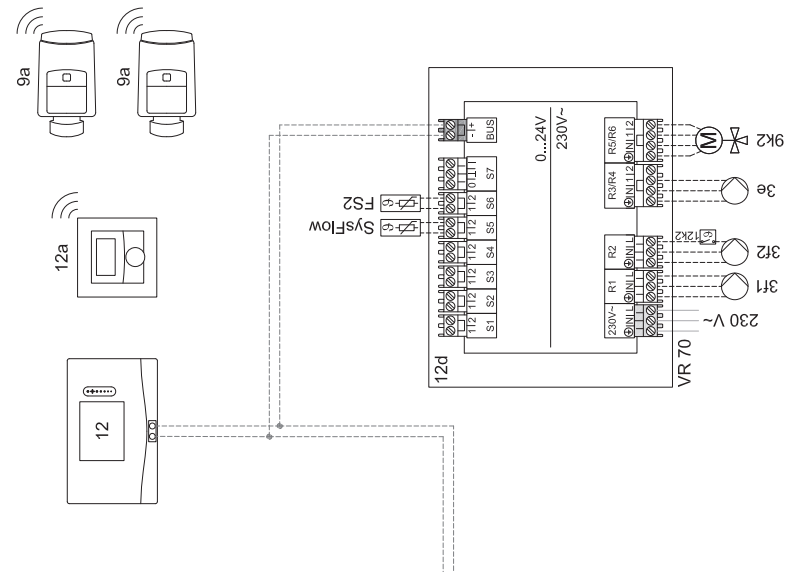
Basic system diagram 0020260774
Special features of the system
17: Optional component
Setting on the system control
- Basic system diagram code: 1
- FM5 configuration: 6
- Circuit 1 / Circuit type: Heating
- Circuit 1 / Room temp. mod.: Active or Expanded
- Circuit 2 / Circuit type: Heating
- Circuit 2 / Room temp. mod.: Active or Expanded
- Circuit 3 / Circuit type: Heating
- Circuit 3 / Room temp. mod.: Active or Expanded
- Zone 1/ Zone activated: Yes
- Zone 1 / Zone assignment: Rem. contr. 1
- Zone 2/ Zone activated: Yes
- Zone 2 / Zone assignment: Rem. contr. 2
- Zone 3/ Zone activated: Yes
- Zone 3 / Zone assignment: Control
Settings at the remote control
- Remote control address: (1): 1
- Remote control address: (2): 2
Basic system diagram 0020260774
Wiring diagram 0020260774
Start-up
Prerequisites for starting up
- the system control and outdoor temperature sensor have been installed and wired.
- The FM5 functional module is installed and connected in accordance with configuration 1, 2, 3 or 6, see supplement.
- The FM3 functional modules are installed and connected, see supplement. A unique address is assigned to each FM3 functional module via the address switch.
- Start-up of all system components (except for the system control) is complete.
Running the installation assistants
The installation assistant is at the Language: query. The system control’s installation assistant takes you through a list of functions. For each function, you should choose the set value that is best suited to the heating installation being installed.
Completing the installation assistant
Once you have gone through the installation assistant, Select the next step. appears on the display
- Installation configuration: The installation assistant switches to the system configuration for the installer level, in which you can further optimise the heating installation.
- Installation start: The installation assistant switches to the basic display and the heating installation works with the values you have set.
Sensor/actuator test: The installation assistant switches to the sensor/actuator test function. You can test the sensors and actuators here.
Changing the settings later
All settings that you have made via the installation assistant can be changed again at a later date via the end user or installer level.
Fault and maintenance messages
Fault
How to respond if the heat pump fails
The system control switches to limp home mode, i.e. the back-up boiler supplies the heating installation with heating energy. During installation, the competent person has restricted the temperature for limp home mode. You can feel thatthe domestic hot water and heating are not becoming very hot.
You can select one of the following settings until the competent person arrives:
- Off: The heating and domestic hot water only become moderately hot.
- Heating: The back-up boiler takes over the heating mode; the heating becomes hot and the domestic hot water is cold.
- DHW: The back-up boiler takes over the domestic hot water mode; the domestic hot water becomes hot and the heating is cold.
- DHW + heat.: The back-up boiler takes over the heating and domestic hot water mode; the heating and domestic hot water become hot.
The back-up boiler is not as efficient as the heat pump, meaning that using only the back-up boiler to generate heat is expensive.
Troubleshooting (→ Appendix)
Fault message
with the text of the fault message appears in the display.
You can find fault messages under: MENU → SETTINGS → Installer level → Fault history Troubleshooting (→ Appendix)
Maintenance message
with the text of the maintenance message appears in the display.
Maintenance message (→ Appendix)
Information about the product
Observing and storing other applicable documents
- Observe all of the instructions that are intended for you and are enclosed with the components of the installation.
- As the end user, keep these instructions and all other applicable documents safe for future use.
Validity of the instructions
These instructions apply only to: – 0020260921
Data plate
The data plate is located on the rear of the product.
| Information on the data plate | Meaning |
| Serial number | for identification; 7th to 16th digits = product article number |
| sensoCOMFORT | Product designation |
| V | Rated voltage |
| mA | Rated current |
| Read the instructions |
Serial number
You can call up the serial numbers under MENU → INFORMATION → Serial number. The 10-digit article number is located in the second line.
CE marking
The CE marking shows that the products comply with the basic requirements of the applicable directives as stated on the declaration of conformity.
The declaration of conformity can be viewed at the manufacturer’s site.
Guarantee and customer service
Guarantee
You can find information about the manufacturer’s guarantee in the Country specifics.
Customer service
The contact details for our customer service are provided on the back page or on our website.
Recycling and disposal
- The competent person who installed your product is responsible for the disposal of the packaging.
If the product is labelled with this mark: - In this case, do not dispose of the product with the household waste.
- Instead, hand in the product to a collection centre for waste electrical or electronic equipment.
Packaging
- Dispose of the packaging correctly.
- Observe all relevant regulations.
Product data in accordance with EU Ordinance no. 811/2013, 812/2013
On units with integrated weather-compensated controls, including a room thermostat function that can be activated, the seasonal room-heating efficiency always includes the correction factor for control technology class VI. The seasonal room-heating efficiency may deviate if this function is deactivated.
| Temperature control class | VI |
| Contribution to the seasonal room-heat- ing energy efficiency ɳs | 4.0 % |
Technical data – System control
| Rated voltage | 9 to 24 V |
| Rated surge voltage | 330 V |
| Pollution degree | 2 |
| Rated current | < 50 mA |
| Supply line cross-section | 0.75 … 1.5 mm² |
| IP rating | IP 20 |
| Protection class | III |
| Temperature for the ball pressure test | 75 ℃ |
| Maximum permitted environmental tem- perature | 0 … 60 ℃ |
| Current room air hum. | 35 … 95 % |
| Mode of operation | Type 1 |
| Height | 109 mm |
| Width | 175 mm |
| Depth | 26 mm |
Troubleshooting, maintenance message
troubleshooting
| Symptom | Possible cause | Measure |
| Display remains dark | Software error | 1. Press and hold the button on the top right of the system con- trol for longer than five seconds in order to force a restart.
2. Switch off the mains switch on all heat generators for approx. 1 minute and then switch them on again. 3. If the fault message persists, inform the competent person. |
| No changes in the display can be made via the control ele- ments | Software error | 1. Press and hold the button on the top right of the system con- trol for longer than five seconds in order to force a restart.
2. Switch off the mains switch on all heat generators for approx. 1 minute and then switch them on again. 3. If the fault message persists, inform the competent person. |
| Display: Button lock activated, it is not possible to change the settings or values | Button lock is active | ▶ Press the button on the top right of the system control for ap-
prox one second in order to deactivate the button lock. |
| Display: Mode: Back-up boiler if fault occurs Heat pump (call the comp. person), insufficient heating-up of the heating and the domestic hot water | Heat pump does not work | 1. Inform the competent person.
2. Select the setting for limp home mode until the competent person arrives. 3. You can find more detailed explanations under Faults, fault messages and maintenance messages (→ Page 43). |
| Display: F. Boiler fault, the specific fault code (e.g. F.33) with the specific boiler is shown in the display | Boiler fault | 1. Reset the boiler by first selecting Reset and then Yes.
2. If the fault message persists, inform the competent person. |
| Display: You do not understand the set language | Incorrect language set | 1. Press twice.
2. Select the last menu item ( SETTINGS) and confirm by pressing . 3. Under SETTINGS, select the second menu item and confirm by pressing . 4. Select the language that you understand and confirm by pressing . |
Maintenance messages
| # | Message | Description | Maintenance work | Interval | |
| 1 | Water defi- ciency: Follow the instructions in the heat gen. | The water pressure is too low in the heating installation. | Refer to the operating instruc- tions for the relevant heat gen- erator for information on filling with water | See the operating instructions for the heat generator |
Troubleshooting
| Symptom | Possible cause | Measure | |
| Display remains dark | Software error | 1. Press and hold the button on the top right of the system con- trol for longer than five seconds in order to force a restart.
2. Switch the mains switch on the heat generator that feeds the system control off and back on again. |
|
| No power supply on the heat generator | ▶ | Re-establish the power supply to the heat generator; this is the same power supply that feeds the system control. | |
| The product is defective | ▶ | Replace the product. | |
| No changes in the display can be made via the control ele- ments | Software error | ▶ | Switch the mains switch on the heat generator that feeds the system control off and back on again. |
| The product is defective | ▶ | Replace the product. | |
| Symptom | Possible cause | Measure |
| Heat generator continues to heat once the room temperature has been reached | Incorrect value in the Room temp. mod.: or Zone assign- ment: function | 1. In the Room temp. mod.: function, set the value Active or
Expanded. 2. In the zone in which the system control is installed, assign the system control’s address in the Zone assignment: func- tion. |
| The heating installation remains in domestic hot water mode | Heat generator cannot reach the max. target flow temperat- ure | ▶ Reduce the set value in the Max. target flow temperature:°C
function. |
| Only one of several heating circuits is displayed | Heating circuits inactive | ▶ In the Circuit type: function, define the required function for
the heating circuit. |
| It is not possible to switch to the installer level | You do not know the code for the installer level | ▶ Reset the system control to the factory setting. All set values
will be lost. |
| Message | Possible cause | Measure | |
| Ventilation unit communication interrupted | Incorrect plug connection | ▶ | Check the plug connection. |
| The cable is defective | ▶ | Replace the cable. | |
| HP control module communica- tion interrupted | Incorrect plug connection | ▶ | Check the plug connection. |
| The cable is defective | ▶ | Replace the cable. | |
| Outdoor temperature sensor signal invalid | Outdoor temperature sensor defective | ▶ | Replace the outdoor temperature sensor. |
| Heat generator 1 communica- tion interrupted *,
* Can be heat generator 1 to 8 |
The cable is defective | ▶ | Replace the cable. |
| Incorrect plug connection | ▶ | Check the plug connection. | |
| FM3 address 1 communication interrupted *,
* Can be address 1 to 3 |
The cable is defective | ▶ | Replace the cable. |
| Incorrect plug connection | ▶ | Check the plug connection. | |
| FM5 communication interrupted | The cable is defective | ▶ | Replace the cable. |
| Incorrect plug connection | ▶ | Check the plug connection. | |
| Remote control 1 communica- tion interrupted *,
* Can be address 1 to 3 |
The cable is defective | ▶ | Replace the cable. |
| Incorrect plug connection | ▶ | Check the plug connection. | |
| Domestic hot water station com- munication interrupted | The cable is defective | ▶ | Replace the cable. |
| Incorrect plug connection | ▶ | Check the plug connection. | |
| Solar pump station communica- tion interrupted | The cable is defective | ▶ | Replace the cable. |
| Incorrect plug connection | ▶ | Check the plug connection. | |
| FM3 configuration [1] not cor- rect *,
* Can be address 1 to 3 |
Incorrect set value for the FM3 | ▶ | Set the correct set value for the FM3. |
| Mixer module no longer suppor- ted | Unsuitable module connected | ▶ | Install a module that the control supports. |
| Solar module no longer suppor- ted | Unsuitable module connected | ▶ | Install a module that the control supports. |
| Remote control no longer sup- ported | Unsuitable module connected | ▶ | Install a module that the control supports. |
| Basic system diagram code not correct | Incorrectly selected basic sys- tem diagram code | ▶ | Set the correct basic system diagram code. |
| Remote control 1 missing *,
* Can be remote control 1 or 2 |
Missing remote control | ▶ | Connect the remote control. |
| Current basic system diagram does not support FM5 | FM5 connected in the heating installation | ▶ | Remove the FM5 from the heating installation. |
| Incorrectly selected basic sys- tem diagram code | ▶ | Set the correct basic system diagram code. | |
| FM3 missing | Missing FM3 | ▶ | Connect the FM3. |
| DHW temperature sensor S1 missing at FM3 | Domestic hot water temperature sensor S1 not connected | ▶ | Connect the domestic hot water temperature sensor to the FM3. |
| Solar pump 1 reports faults *, * Solar pump 1 or 2 | Fault in the solar pump | ▶ | Check the solar pump. |
| Message | Possible cause | Measure | |
| Shift-load cylinder no longer supported | Unsuitable cylinder connected | ▶ | Remove the cylinder from the heating installation. |
| HP control module MO2 config- uration not correct | Incorrectly connected FM3 | 1. Remove the FM3.
2. Select a suitable configuration. |
|
| Incorrectly connected FM5 | 1. Remove the FM5.
2. Select another configuration. |
||
| FM5 configuration not correct | Incorrect set value for the FM5 | ▶ | Set the correct set value for the FM5. |
| Cascade not supported | Incorrectly selected system dia- gram | ▶ | Set the correct system diagram that contains cascades. |
| FM3 configuration [1] MO not correct *, * Can be address 1 to 3 | Incorrect component selection for the MO | ▶ | Select the component in the FM3 MO function that is appropri- ate for the connected component on the FM3’s multi-function output. |
| FM5 configuration MO not cor- rect | Incorrect component selection for the MO | ▶ | Select the component in the FM5 MO function that is appropri- ate for the connected component on the FM5’s multi-function output. |
| Room temp. sensor signal on control invalid | Room temperature sensor de- fective | ▶ | Replace the control. |
| Room temp. sensor signal on remote control 1 invalid *, * Can be address 1 to 3 | Room temperature sensor de- fective | ▶ | Replace the remote control. |
| S1 sensor signal at FM3 ad- dress 1 invalid *, * Can be S1 to 7 and address 1 to 3 | Sensor defective | ▶ | Replace the sensor. |
| S1 sensor signal at FM5 invalid
*, * Can be S1 to S13 |
Sensor defective | ▶ | Replace the sensor. |
| Heat generator 1 reports faults
*, * Can be heat generator 1 to 8 |
Fault in the heat generator | ▶ | See the instructions for the heat generator displayed. |
| Ventilation unit reports faults | Ventilation unit fault | ▶ | See instructions for the ventilation unit. |
| HP control module reports faults | Fault in the heat pump control module | ▶ | Replace the heat pump control module. |
| Assignment of remote control 1 missing *, * Can be address 1 to 3 | The assignment of remote con- trol 1 to the zone is missing. | ▶ | Assign the correct address to the remote control in the Zone assignment: function. |
| Zone activation missing | A zone that is in use is not yet activated. | ▶ | In the Zone activated: function, select the value Yes. |
| Heating circuits inactive | ▶ | In the Circuit type: function, define the required function for the heating circuit. | |
Maintenance messages
| # | Message | Description | Maintenance work | Interval | |
| 1 | Heat generator 1 requires main- tenance *, * Can
be heat generator 1 to 8 |
The heat generator requires maintenance work. | Refer to the operating or install- ation instructions for the relev- ant heat generator for informa- tion on the maintenance work required | See the operating or installation instructions for the heat gener- ator | |
| 2 | Ventilation unit requires main- tenance | The ventilation unit requires maintenance work. | Refer to the operating or install- ation instructions for the relev- ant ventilation unit for informa- tion on the maintenance work required | See the operating or installation instructions for the ventilation unit | |
| 3 | Water defi- ciency: Follow the instructions in the heat gen. | The water pressure is too low in the heating installation. | Water deficiency: Follow the in- structions in the heat generator | See the operating or installation instructions for the heat gener- ator | |
| 4 | Maintenance Contact: | Date on which maintenance is due for the heating installation. | Carry out the required mainten- ance work | Date entered in the control |
REFERENCE:
DOWNLOAD MANUALS:
Vaillant VRC 720 sensoCOMFORT Programmable Thermostat Installation Instructions
![]()
Vaillant VRC 720 sensoCOMFORT Programmable Thermostat Installation Instructions
Leave a Reply