
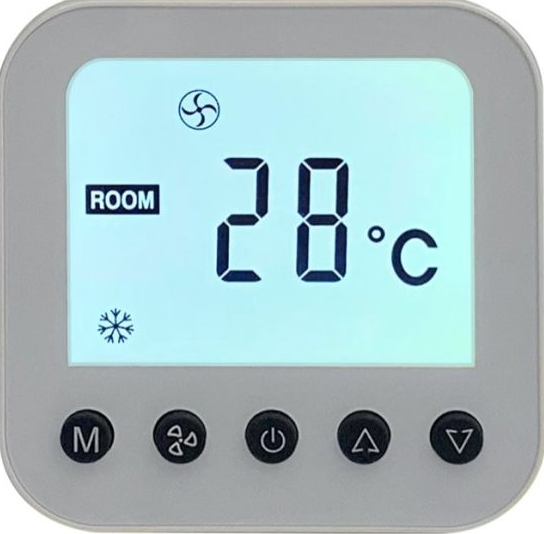
TRUEWAY TX892 Room Digital Thermostat
APPLICATIONS
- TX892 Series is a digital button type thermostat with many variants suitable for 2-pipe cooling & heating fan coil units Available in basic standalone and Modbus communicating variants
- Backlight is available for sky blue TN LCD Fitted with built-in N TC 10K sensor and optional humidity sensor. Several add-on functions like remote sensor, and `key card can be chosen as per site requirements
FEATURES
- Classic button-type design suitable for offices, hotels, and residential buildings
- Applicable for 2-pipe FCU cooling & heating,
- Sky-blue LCD display
- Special colors casing upon request with RAL number can be provided
- Either room temperature or set-point is displayed.
- Manual & Automatic fan functions
- User settings can be kept during power off
- Fan load 5A resistive and inductive of 3A
- Big LCD with English display
- Temperature unit C&F
- Regular color available in Black and White body
- EC motor variants available
- Fits in a 75mmx75mm electrical junction box
SPECIFICATION
- Power Supply: 85-240VAC / 24VAC• Frequency: 50~60Hz
- Function: Cooling/Heating
- Relay Life: 220±10% VAC, 3(5)A, 100,000 times
- Wiring Max: 16AWG
- Sensing Element: 10K(@25°C) NTC
- Display Accuracy: 1°C, Set-point accuracy: 1°C/step
- Set-point range: 10-32°C(50-90°F)
- Display range: 0-50°C
- Protection Glass: IP 20
- Operation Temperature: -18~49°C
- Shipping Temperature: -35~65°C
- Suitable System: 2-pipe
- FCU cooling&heating,
- Suitable Valve: 2-line/3-line valve
- Relative Humidity: 10~90%
- Installed on 75mm x 75mm box
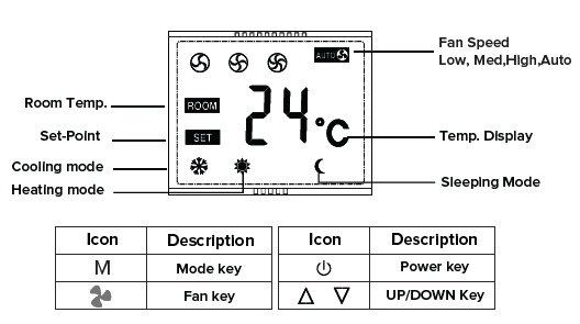
LCD DISPLAY & KEYS DESCRIPTION
FUNCTION
- 2-pipe FCU cooling&heating,
- Simple on-off output.
- Speed Fan + Auto Fan Control
- Energy Save Mode and
- Comfort Mode Settings
- Key Pad Lock
- Either Room Temperature or set-point is Displayed
ORDERING PART NUMBERS
| PART NUMBERS | OPERATING VOLTAGES | APPLICATIONS | VALVE TYPE | ADDON FUNCTIONS |
|
TX892OF220-V2E |
85-240VAC |
2-PIPE |
ON-OFF VALVE |
EXTERNAL SENSOR |
|
TX892OF220-V2K |
85-240VAC |
2-PIPE |
ON-OFF VALVE |
HOTEL KEYCARD |
|
TX892OF024-V2 |
24VAC |
2-PIPE |
ON-OFF VALVE |
N/A |
ABBREVIATION
| CASING/COVER COLOR | |
|
BLACK |
B |
|
WHITE |
W |
| BACKLIGHT COLOR | |
|
Sky Blue backlight + Black letters (TN LCD) |
SB |
OPERATION INSTRUCTION
ON-OFF VALVE /COMPRESSOR CONTROL
The thermostat acquires the room temperature via its integrated sensor and maintains the set-point by simple on-off output
POWER ON OR OFF
Pressing the POWER button![]() to change the power ON/OFF status
to change the power ON/OFF status
INCREASE / DECREASE
In the ON state, press UP![]() or DOWN
or DOWN to increase or decrease the setting parameters
HEAT/COOL/VENT
Pressing the MODE button M to select heat ![]()
TEMPERATURE DISPLAY
Either room temperature or set-point is displayed
Noted: When pressing UP or Down button, the set-point will be displayed, When no operation (button pressed) after a few seconds,the room temperature will be display instead.
COMFORT MODE
In the comfort mode, the set point can be changed by pressing UP or DOWN buttons Different applications include cool only heat only and manual heat/cool changeover.
FAN OPERATION
Fan can be selected as manual or automatic 3-speed operation. In manual mode, the fan will be switched to the selected speed via control output Gh,Gm,Gl (by pressing FAN button![]() ). In automatic mode, the fan speed will be switched upon the difference between the room temperature and the setpoint When room temperature reaches set-point, valve will be closed meanwhile fan will be turned of as well.
). In automatic mode, the fan speed will be switched upon the difference between the room temperature and the setpoint When room temperature reaches set-point, valve will be closed meanwhile fan will be turned of as well.
KEY LOCK
The default status of “Key lock” is all keys available and it can be changed in ISU mode. Key lock function includes the following settings: All keys are available (Default) Mode button is locked out. Fan and Mode button are locked out. All buttons are locked.
SETUP FUNCTION SETTINGS AND OPTIONS
- Press “ M ” and “
 ” key for 5 seconds to enter ISU setting mode, the ISU code will be flashing.
 - Press orto select the ISU setting items from 1-10 .
- Press “ M ” and the symbol of “ ” will be displayed, press “ ”or “ ” to revise the values of the setting items, press “ M ”to confirm.
| ISU CODE | DESCRIPTION | POSSIBLE OPTIONS |
| 1 | SYSTEM TYPE | 0 HEAT ONLY 1COOL ONLY 2 TWO PIPES 1H1C MANUAL(DEFAULT) |
| 2 | TEMPERATURE UNIT | F : ° F C : ° C(DEFAULT) |
| 3 | FAN CONTROL TYPE | AO: AUTO ONLY CO: CONSTANT ONLY BO : BOTH(DEFAULT) |
| 4 | KEYPAD LOCKOUT | 0: ALL KEYS ARE AVAILABLE (DEFAULT) 1: THE MODE BUTTON IS LOCKED OUT, AFTER LOCKED OUT, WHEN YOU PRESS MODE KEY, IT WILL DISPLAY “LOC” 2: FAN AND MODE BUTTONS ARE LOCKED OUT, AFTER LOCKED OUT,WHEN YOU PRESS FAN OR MODE BUTTON, IT WILL DISPLAY” LOC” 3: ALL BUTTONS ARE LOCKED, AFTER LOCKED OUT WHEN YOU PRESS ANY KEYS, IT WILL DISPLAY” LOC” |
| 5 | DISPLAY TEMP. ADJUSTMENT | -9°C/ °F ~ + 9°C/°F |
| 6 | RESERVED FOR ADDITIONAL ISU SETTINGS. | |
| 7 | RESERVED FOR ADDITIONAL ISU SETTINGS. | |
| 8 | SENSOR SELECTION | IN : INTERNAL SENSOR, OU : EXTERNAL SENSOR, IF CHOOSING OU EXTERNAL SENSOR, THE ROOM CARD FUNCTION WILL NOT BE AVAILABLE (DEFAULT IN) |
|
9 |
BACK-LIGHT TIME SETTING |
10-90 SECONDS(DEFAULT 30 SEC., USER CAN ADJUST BACK-LIGHT TIME ACCORDING TO ACTUAL DEMANDS) |
| 10 | RESERVED FOR ADDITIONAL ISU SETTINGS. | |
WIRING DIAGRAM
| NO | TERMINALS | DESCRIPTION | NO | TERMINALS | DESCRIPTION | NO | TERMINALS | DESCRIPTION | ||
| 1 | L | LIVE IN | 1 | L | LIVE IN | 1 | R | 24V ACTIVE | ||
| 2 | FH | HIGH SPEED FAN | 2 | FH | HIGH SPEED FAN | 2 | LINE | 220V LINE FOR 220V FAN | ||
| 3 | FM | MEDIUM SPEED FAN | 3 | FM | MEDIUM SPEED FAN | 3 | FH | HIGH SPEED FAN | ||
| 4 | FL | LOW SPEED FAN | 4 | FL | LOW SPEED FAN | 4 | FM | MEDIUM SPEED FAN | ||
| 5 | NO | VALVE OPEN | 5 | NO | VALVE OPEN | 5 | FL | LOW SPEED FAN | ||
| 6 | NC | VALVE CLOSE | 6 | NC | VALVE CLOSE | 6 | C | 24V NEUTRAL | ||
| 7 | N | NEUTRAL IN | 7 | N | NEUTRAL IN | 7 | NO | VALVE OPEN | ||
| 8 | COM | COM FOR EXTERNAL SENSOR | 8 | COM | COM FOR KEY CARD | 8 | NC | VALVE CLOSE | ||
| 9 | AI | EXTERNAL SENSOR | 9 | DI | KEY CARD | 9 |
TERMINAL POWER BOX
*wiring is subject to change without notice based on addons
NOTE
- The thermostat is high voltage input, please do the wiring with the technician.
- If the thermostat was burned by accident, please do not wire it again by yourself, try to check it with a professional technician or contact our manufacturer
PRODUCT DIMENSION
INSTALLATION AND COMMISSIONING
- Take the front panel and back plate apart by a screwdriver
- Wiring on the terminals of the back plate according to the above wiring diagram, then fix the back plate on the junction box by screwdriver
- Recombine the front panel and back plate with contact pins
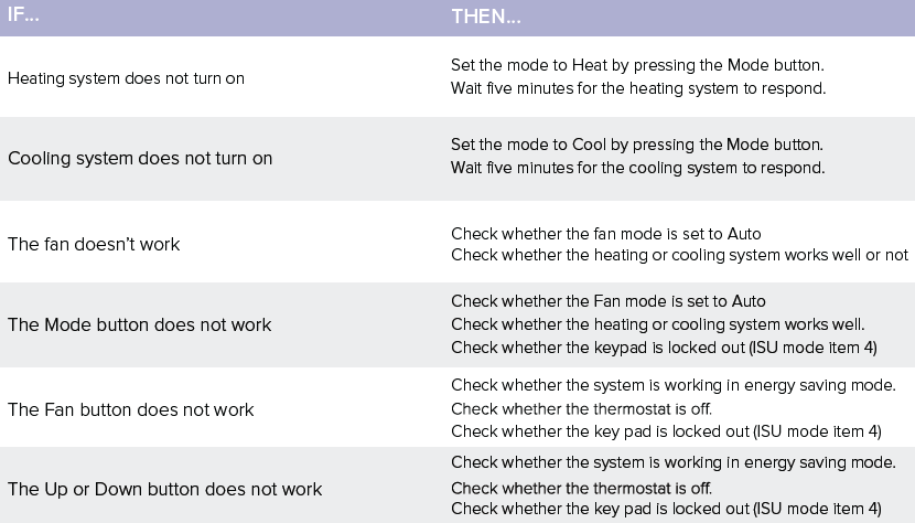
TROUBLESHOOTING
Office:
- Trueway Controls Hong Kong Limited
- Room 1318-19 Hollywood Plaza,
- 610 Nathan Road, Mongkok,
- Kowloon, Hong Kong.
REFERENCE:
DOWNLOAD MANUALS:
TRUEWAY TX892 Room Digital Thermostat User Manual
![]()
Leave a Reply