
tekmar 552_D Programmable Thermostat
Introduction
The tekmarNet® Thermostat 552 provides operation for:
- One Stage Heat
Features
- Touchscreen
- Bright Backlight tekmarNet® Communication
- Outdoor Temperature Display
- Floor Temperature Display
- 7-Day, 4 Event Programmable
- Schedule
- Optimum Start
- Scenes
- Away Key
- Air Group Member
- Freeze Protection
- Exercise Pump or Valves
- Zone Synchronization
- Two Auxiliary Sensor Inputs
Benefits
- Simple to Use
- Increased Comfort Through
- Precise Temperature Control
- Conserves Energy
- Convenience Through Internet
- Connectivity
- Warm Radiant Floors
- Protects Radiant Floors From
- Over Heating
Important Safety Information
- It is your responsibility to ensure that this thermostat is safely installed according to all applicable codes and standards. tekmar is not responsible for damages resulting from improper installation and/or maintenance
- This is a safety-alert symbol. The safety alert symbol is shown alone or used with a signal word (DANGER, WARNING, or CAUTION), a pictorial and/or a safety message to identify hazards.
- When you see this symbol alone or with a signal word on your equipment or in this Manual, be alert to the potential for death or serious personal injury.
- This pictorial alerts you to electricity, electrocution, and shock hazards.
- This symbol identifies hazards which, if not avoided, could result in death or serious injury.
- This symbol identifies hazards which, if not avoided, could result in minor or moderate injury.
- This symbol identifies practices, actions, or failure to act which could result in property damage or damage to the equipment.
- Read Manual and all product labels BEFORE using the equipment. Do not use unless you know the safe and proper operation of this equipment. Keep this Manual available for easy access by all users. Replacement
- Manuals are available at tekmarControls.com
- It is the installers responsibility to ensure that this thermostat is safely installed according to all applicable codes and standards.
- Improper installation and operation of this thermostat could result in damage to the equipment and possibly even personal injury or death.
- This thermostat is not intended for use as a primary limit control. Other controls that are intended and certified as safety limits must be placed into the control circuit.
Getting Started
Congratulations on the purchase of your new tekmar thermostat. This manual will step through the complete installation, programming and sequence of operation for this control. At the back, there are tips for control and system troubleshooting.
Installation
Preparation
Tools Required
- tekmar or jeweller screwdriver
- Phillips head screwdriver
- Wire Stripper
Materials Required
- 18 AWG LVT Solid Wire
- (Low Voltage Connections
Installation Location
Choose the placement of the thermostats early in the construction process to enable proper wiring during rough-in.
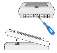
Removing The Thermostat Base
- To remove the thermostat base:
- Locate the tab on the bottom of the thermostat.
- Push the tab with either your thumb or with a screwdriver.
- Lift the thermostat front away from the thermostat’s base.
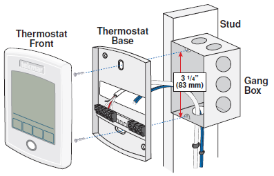
Mounting The Thermostat Base
- If a single gang box is used:
- Feed the wiring through the large hole of the thermostat base.
- Fasten the base of the thermostat to the gang box.
- Terminate wiring to the wiring strip.
- Push the thermostat front onto the thermostat base.
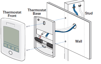
If a gang box is not used:
- Feed the wiring through the large hole in the thermostat base.
- Mount the thermostat base directly to the wall.
- Use screws in the screw holes to fasten the thermostat to the wall.
- At least one of the screws should enter a wall stud or similar rigid material.
- Terminate wiring to the wiring strip.
- Push the thermostat front onto the thermostat base.
Thermostat Wiring
- The thermostat operates a single heating system zone and can be wired in four different ways.
- tekmarNet®2 – Allows the thermostat to be wired point-to-point using 2 wires to a
- tekmarNet®2 Wiring Center, House Control, or Zone Manager. This allows easy wiring for retrofit applications.
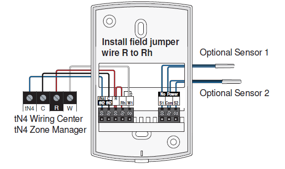
- tekmarNet®4 – Allows the thermostat to be wired using 4 wires to a tekmarNet Wiring
- Center or Zone Manager point-to-point. Alternatively, the thermostat can operate heating equipment locally and the tN4 communication bus can be daisy-chained from one thermostat to another.
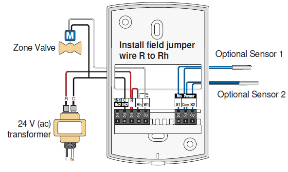
- Stand Alone – Simple 3 wire connection to a 24 V (ac) transformer and zone valve.
- Stand Alone – Simple 3 wire connection to a switching relay or zone valve control
Wiring – tekmarNet®2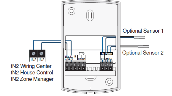
Wiring – tekmarNet® 4
Wiring – Stand Alone to Transformer and Zone Valve
Wiring – Stand Alone to Switching Relay or Zone Valve Control
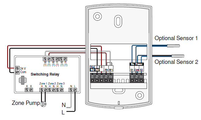
Compatible Sensors
The thermostat is compatible with Indoor Sensor type 076, 077, 084, Floor Sensor type 072, 073, 079, and Outdoor Sensor type 070.
Testing the Thermostat Wiring
- Remove the thermostat front.
- Use an electrical meter to measure DC voltage between the tN2 terminals.
- If the DC voltage is 0 V (dc) for at least 20 seconds, then there is an open or short circuit in the tN2 wires.
- If the DC voltage is 0 V (dc) for 10 seconds and then is 23 to 24 V (dc) for 5 seconds, this indicates the wiring is correct.
- Connect the thermostat to the tN2 wires connected to a zone on a House Control, Wiring Center, or Zone Manager.
- If the thermostat display is off, or is cycling on and off, move the thermostat to the next available zone on the House Control, Wiring Center, or Zone Manager.
- If the thermostat display remains permanently on, there may be a fault with the previously tried zone on the House Control, Wiring Center, or Zone Manager.
- If the thermostat display continues to be off, or is cycling on and off, there may be a fault on the thermostat.
- If a fault is suspected, contact your tekmar sales representative for assistance.
Testing the Heat Zone Output Wiring
- Touch the button and set the heating temperature above the current room temperature. Make sure the display does not show “WWSD” or “Floor Max”.
- When the “Heat On” symbol appears on the display, use an electrical meter to check for voltage on the House Control, Wiring Center, or Zone Manager relay.
- The voltage is 24 V (ac) for zone valves, and 120 V (ac) for zone pumps when operating correctly.
Testing the Power
- Remove the front cover from the thermostat.
- Use an electrical test meter to measure (ac) voltage between the R and C terminals.
- The reading should be 24 V (ac) +/– 10%.
- Install the front cover.
Testing the Heat Relay
- Remove the front cover from the thermostat.
- Touch the button and set the heating temperature below the current room temperature. There should be no “Heat On” symbol on the display.
- Set the electrical test meter to continuity.
- Place electrical meter probes between R and W. There should be no continuity. If there is continuity then there may be a wiring fault or the relay may be faulty.
- Touch the button and set the heating temperature above the current room temperature. Make sure the display does not show “WWSD”. The “Heat On” symbol should appear on the display.
- There should now be continuity between the R and W terminals.
Testing the tekmarNet®4 Bus Wiring
- The symbol is shown on the display when communication is present.
- If the thermostat is connected in a network and the communication is missing, there may be an open or short circuit on the tN4 and C bus wires.
- Remove the front cover from the thermostat.
To test for short circuits:
- Disconnect the tN4 bus wires on one end.
- Install wire nuts on each wire to ensure the wire ends are not touching.
- Disconnect the tN4 bus wires on the other end.
- Measure for continuity using an electrical meter.
- If continuity is present, there is a short circuit fault along the wires. It is recommended to replace the tN4 bus wires.
To test for open circuits:
- Disconnect the tN4 bus wires on one end and connect them together.
- Disconnect the tN4 bus wires on the other end.
- Use an electrical meter to measure for continuity.
- If there is no continuity, there is an open circuit fault along the wires. It is recommended to replace the tN4 bus wires.
Mounting the Thermostat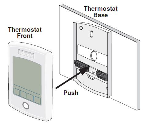
Cleaning the Thermostat
The thermostats’s exterior can be cleaned using a damp cloth. Moisten the cloth with water and wring out prior to wiping the control. Do not use solvents or cleaning solutions
Switch Settings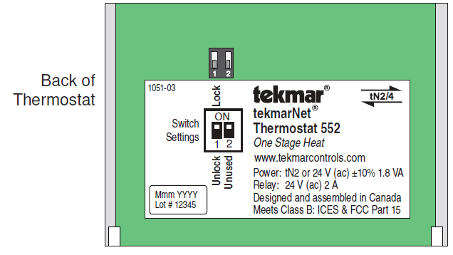
| Switch | Position | Action |
|
1 |
ON |
LOCK ACCESS LEVEL
Thermostat is locally locked and the access level cannot be changed. Set to Lock when installation has been completed. |
|
OFF |
UNLOCK ACCESS LEVEL
Thermostat is unlocked and the access level may be changed. Go to the Toolbox menu to change the access level. Set to Unlock during the installation process. Note: tekmarNet® system controls include a Global Lock that locks all connected thermostats. Set the tekmarNet® system control to unlock to allow access level adjustment on all connected thermostats. |
User Interface
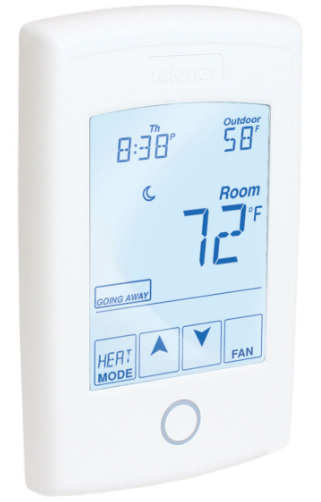
Home Screen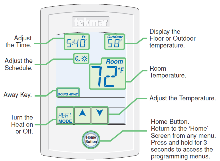
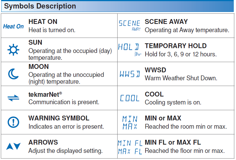
Symbols Description
Programmable Settings
Press and hold the Home button for 3 seconds to enter the programming menus. The thermostat returns to the last programming menu previously used.
Select a Programming Menu
- Touch “NEXT” to advance (clockwise in above illustration) to the next menu.
- Touch “BACK” to go backwards (counterclockwise in above illustration) through the menus.
- Touch “ENTER” to enter a menu.
Setting Items
- Touch or arrow to adjust the setting if required.
- Touch “NEXT ITEM” to advance to the next item within the menu.
- Touch “BACK ITEM” to go backwards to the previous item within the menu.
- To return to the parent menu after changing a setting, press and release the home button.
- To return to the home screen, press and release the home button twice or wait 30 seconds to automatically return to the home screen
Set Temp Menu (1 of 3)
| Set Temp Menu (1 of 3) | |
| Setting | Display |
| SET HEAT ROOM
Set the room heating temperature during the event. |
Room
|
| Access Level: Installer, User | Range: 40 to 95°F (4.5 to 35.0°C) |
| Conditions: Room Sensor set to ON or Sensor 1 or Sensor 2 set to Room. | Default: 70°F (21.0°C) |
| SET HEAT ROOM
Set the room heating temperature during the event. |
Room
|
| Access Level: Installer, User | Range: 40 to 95°F (4.5 to 35.0°C) |
| Conditions: Room Sensor set to ON or Sensor 1 or Sensor 2 set to Room, and Schedules are in use or Scenes are set to All or Guest. |
Default: 65°F (18.5°C) |
| SET HEAT ROOM AWAY
Set the room heating temperature during the Away scene. |
Room |
| Access Level: Installer, User | Range: 40 to 95°F (4.5 to 35.0°C) |
| Conditions: Room Sensor set to ON or Sensor 1 or Sensor 2 set to Room, and Scenes is set to Away, All or Guest. |
Default: 62°F (16.5°C) |
| ROOM MAX
Set the maximum room heating limit while in the event. |
|
| Access Level: Installer | Range: 40 to 95°F (4.5 to 35.0°C) |
| Conditions: Room Sensor set to ON or Sensor 1 or Sensor 2 set to Room. | Default: 85°F (29.5°C) |
| ROOM MAX
Set the maximum room heating limit while in the event. |
|
| Access Level: Installer | Range: 40 to 95°F (4.5 to 35.0°C) |
| Conditions: Room Sensor set to ON or Sensor 1 or Sensor 2 set to Room, and Schedules are in use or Scenes are set to All or Guest. |
Default: 85°F (29.5°C) |
| SET HEAT FLOOR
Set the floor heating temperature while in the event. |
Floor |
| Access Level: Installer, User | Range: 40 to 122°F (4.5 to 50.0°C) |
| Conditions: Room Sensor set to OFF and Sensor 1 or Sensor 2 set to Floor. | Default: 72°F (22.0°C) |
| Set Temp Menu (2 of 3) | |
| Setting | Display |
| SET HEAT FLOOR
Set the floor heating temperature while in the event. |
Floor |
| Access Level: Installer, User | Range: 40 to 122°F (4.5 to 50.0°C) |
| Conditions: Room Sensor set to OFF and Sensor 1 or Sensor 2 set to Floor, and Schedules are in use or Scenes are set to All or Guest. |
Default: 65°F (18.5°C) |
| WARM WEATHER SHUT DOWN
Set the outdoor air temperature at which heating is suspended during the event. |
|
| Access Level: Installer | Range: CTRL (control), 40 to 100°F (4.5 to 38.0°C), OFF |
| Conditions: Always available | Default: CTRL |
| WARM WEATHER SHUT DOWN
Set the outdoor air temperature at which heating is suspended during the event. |
|
| Access Level: Installer | Range: CTRL (control), 40 to 100°F (4.5 to 38.0°C), OFF |
| Conditions: Requires that Schedules are in use or Scenes is set to All or Guest. | Default: CTRL |
| FLOOR MINIMUM
Set the floor heating temperature while in the event. |
|
| Access Level: Installer, User | Range: OFF, 40 to 122°F (4.5 to 50.0°C) |
| Conditions: Sensor 1 or Sensor 2 set to Floor, and either Room Sensor set to ON, or Room Sensor set to OFF while Sensor 1 or 2 is set to Room. |
Default: 72°F (22.0°C) |
| FLOOR MINIMUM
Set the floor heating temperature while in the event. |
|
| Access Level: Installer, User | Range: OFF, 40 to 122°F (4.5 to 50.0°C) |
| Conditions: Sensor 1 or Sensor 2 set to Floor, and either Room Sensor set to ON, or Room Sensor set to OFF while Sensor 1 or 2 is set to Room, Schedules are in use or Scenes are set to All or Guest. |
Default: OFF |
| Set Temp Menu (3 of 3) | |
| Setting | Display |
| FLOOR MAXIMUM
Set the floor maximum temperature in order to protect the floor covering. Suggested settings: Tile = 90°F (32°C) Hardwood Floor = 85°F (29°C) |
|
| Access Level: Installer | Range: 40 to 122°F (4.5 to 50.0°C), OFF |
| Conditions: Sensor 1 or Sensor 2 set to Floor, and either Room Sensor set to ON, or Room Sensor set to OFF while Sensor 1 or 2 is set to Room, and Schedules or Scenes are in use. |
Default: 85°F (29.5°C) |
| TEMPORARY HOLD
Temperature adjustment in the home menu can result in either permanent temperature setting change or temporary temperature setting change that lasts 3, 6, 9, 12 hours or until the next sched- uled event. |
|
| Access Level: Installer | Range: OFF or ON |
| Conditions: None | Default: OFF |
Time Menu (1 of 2)
| Time Menu (1 of 2) | |
| Setting | Display |
| MINUTE
Select the current time minutes. |
|
| Access Level: Installer, User | Range: 00 to 59 |
| Conditions: Schedule is used or Clock is set to ON. | Default: 00 |
| HOURS
Select the current time hours. |
|
| Access Level: Installer, User | Range: 12 AM to 11 PM or 00 to 23 |
| Conditions: Schedule is used or Clock is set to ON. | Default: 12 AM |
| DAY OF WEEK
Select the current day of the week. |
|
|
Access Level: Installer, User |
Range: Sunday, Monday, Tuesday, Wednesday, Thursday, Friday, Saturday |
| Conditions: Schedule is used or Clock is set to ON. | Default: Sunday |
| MONTH
Select the current month. |
|
| Access Level: Installer, User | Range: JANUARY to DECEMBER |
| Conditions: Schedule is used or Clock is set to ON. | Default: JANUARY |
| DAY OF MONTH
Select the day of the current month. |
|
| Access Level: Installer, User | Range: 1 to 31 |
| Conditions: Schedule is used or Clock is set to ON. | Default: 1 |
| YEAR
Select the current year. |
|
| Access Level: Installer, User | Range: 2014 to 2255 |
| Conditions: Schedule is used or Clock is set to ON. | Default: 2014 |
| Time Menu (2 of 2) | |
| Setting | Display |
| DAYLIGHT SAVINGS TIME
Select if daylight savings time is observed. |
|
| Access Level: Installer, User | Range: OFF or ON |
| Conditions: Clock setting is set to ON. | Default: ON |
| TIME MODE
Select either 12 or 24 hour time format. |
|
| Access Level: Installer, User | Range: 12 or 24 hour |
| Conditions: Clock setting is set to ON. | Default: 12 hour |
| CLOCK
Select whether or not to show the time clock on the display. |
|
| Access Level: Installer, User | Range: OFF or ON |
| Conditions: The time is always shown when a schedule is used and the clock setting option is no longer available. |
Default: OFF |
| Setting | Display |
| EVENT 1
The first programmable schedule time period of the day. The temperature settings are used during this time period. |
SuMoTuWeThFrSa
|
| Access Level: Installer, User | Range: 12:00 AM to 11:50 PM, SKIP or 00:00 to 23:50, SKIP |
| Conditions: Schedule setting is set to Zone or Master 1, 2, 3, 4 and Event/Day is set to 2 or 4. | Default: 6:00 AM |
| EVENT 2
The second programmable schedule time period of the day. The temperature settings are used during this time period. |
SuMoTuWeThFrSa
|
| Access Level: Installer, User | Range: 12:00 AM to 11:50 PM, SKIP or 00:00 to 23:50, SKIP |
| Conditions: Schedule setting is set to Zone or Master 1, 2, 3, 4 and Event/Day is set to 2 or 4. | Default:
10:00 PM when Event/Day is 2 8:00 AM when Event/Day is 4 |
| EVENT 3
The third programmable schedule time period of the day. The temperature settings are used during this time period. |
SuMoTuWeThFrSa
|
| Access Level: Installer, User | Range: 12:00 AM to 11:50 PM, SKIP or 00:00 to 23:50, SKIP |
| Conditions: Schedule setting is set to Zone or Master 1, 2, 3, 4 and Event/Day is set to 4. | Default: 6:00 PM |
| EVENT 4
The fourth programmable schedule time period of the day. The temperature settings are used during this time period. |
SuMoTuWeThFrSa
|
| Access Level: Installer, User | Range: 12:00 AM to 11:50 PM, SKIP or 00:00 to 23:50, SKIP |
| Conditions: Schedule setting is set to Zone or Master 1, 2, 3, 4 and Event/Day is set to 4. | Default: 10:00 PM |
| Schedule Menu (2 of 2) | |
| Setting | Display |
| SCHEDULE
Select if the thermostat should change the temperature automatically using a programmable schedule. OFF = Programmable schedule is not used. Zone = Applies to this thermostat only. Master 1, 2, 3, 4 = In charge of one of four available network schedules. Member 1, 2, 3, 4 = Follows selected network schedule. |
|
| Access Level: Installer, User | Range: OFF, Zone, Master 1, 2, 3,
4, Member 1, 2, 3, 4 |
| Conditions: In a tekmarNet® system, settings adjustable in Installer access level only. | Default: OFF |
| EVENT PER DAY
Select the number of temperatures per day. |
|
| Access Level: Installer, User | Range: 2 or 4 |
| Conditions: Schedule setting is set to Zone or Master 1, 2, 3, 4. | Default: 2 |
|
24 HOUR / 7 DAY |
|
| Access Level: Installer, User | Range: 24 hour or 7 day |
| Conditions: Schedule setting is set to Zone or Master 1, 2, 3, 4. | Default: 24 hour |
| OPTIMUM START
Select whether or not to use optimum start. The thermostat learns the heat up rate of the radiant floor heating system and starts heating in advance of Event 1 or Event 3. |
|
| Access Level: Installer, User | Range: OFF or ON |
| Conditions: A schedule must be in use. | Default: ON |
| Display Menu (1 of 2) | |
| Setting | Display |
| UNITS
Select Fahrenheit or Celsius as the temperature units. |
|
| Access Level: Installer, User | Range: °F or °C |
| Conditions: Always available. | Default: °F |
| Display Menu (2 of 2) | |
| Setting | Display |
| BACKLIGHT
Select how the display backlight operates. ON = Always full brightness. DIM = Dim when inactive, on when touched. DIM = Dim in , off in . On when touched. ON = On in , off in . On when touched. OFF = Always off. |
|
| Access Level: Installer, User | Range: DIM, ON, DIM , ON , OFF |
| Conditions: Always available. | Default: DIM |
| SECONDARY ITEM
Determine the default item in the upper right hand corner of the display. |
|
| Access Level: Installer, User | Range: NONE, OUT (outdoor), FLOR (floor) |
| Conditions: Always available. | Default: OUT (outdoor) |
| Scenes Menu (1 of 1) | |
| Setting | Display |
| SCENES
Enable or disable the use of scenes (building overrides) on this thermostat. |
|
| Access Level: Installer, User | Range: NONE, AWAY, ALL, GUEST |
| Conditions: Settings ALL and GUEST only available in Installer access level. | Default: NONE |
| SCENE 4
Select how the thermostat should respond to scene 4. |
|
| Access Level: Installer | Range: SCHD, , , Away |
| Conditions: Requires that Schedule is set to Zone, Master or Member 1, 2, 3, 4 and Scenes is set to All. | Default: SCHD (Schedule) |
| AWAY KEY
Enable or disable the away touch key on the home screen. |
|
| Access Level: Installer, User | Range: OFF or ON |
| Conditions: Scene is set to ALL, AWAY, or GUEST. | Default: OFF |
| LOCAL NETWORK GROUP
Select if scenes and time clock are shared when connected to a tekmarNet® system. OFF = Send and receive messages. ON = Receive messages only. |
|
| Access Level: Installer | Range: OFF or ON |
| Conditions: Always available. | Default: OFF |
| Monitor Menu (1 of 3) | |
| Setting | Display |
| ROOM AVERAGE
Current room temperature. Displays the average if there are multiple room sensors. |
|
| Access Level: Installer | Range: -58 to 212°F (-50.0 to 100.0°C) |
| Conditions: Sensor 1 or 2 is set to Room. | Default: Not applicable. |
| FLOOR AVERAGE
Current floor temperature. Displays the average if there are multiple floor sensors. |
|
| Access Level: Installer | Range: -58 to 212°F (-50.0 to 100.0°C) |
| Conditions: Sensor 1 or 2 is set to Floor. | Default: Not applicable. |
| W1 SUPPLY
First stage heating supply water temperature. |
|
| Access Level: Installer | Range: -22 to 266°F (-30.0 to 130.0°C) |
| Conditions: Setup menu setting W1 TERM set to CTRL, HRF1, HRF2, CONV or COIL. | Default: Not applicable. |
| ROOM LOCAL
The built-in room sensor temperature measurement. |
|
| Access Level: Installer | Range: -58 to 212°F (-50.0 to 100.0°C) |
| Conditions: Setup menu setting ROOM SENSOR is set to ON. | Default: Not applicable. |
| SENSOR 1
The temperature measurement from the sensor 1 input wiring terminals. |
|
| Access Level: Installer | Range: -22 to 266°F (-30.0 to 130.0°C) |
| Conditions: Setup menu setting SENSOR 1 is set to ROOM, FLOR, or OUT. | Default: Not applicable. |
| SENSOR 2
The temperature measurement from the sensor 2 input wiring terminals. |
|
| Access Level: Installer | Range: -22 to 266°F (-30.0 to 130.0°C) |
| Conditions: Setup menu setting SENSOR 2 is set to ROOM or FLOR. | Default: Not applicable. |
| Monitor Menu (2 of 3) | |
| Setting | Display |
| OUTDOOR HIGH
The highest recorded outdoor air temperature measurement. Touch the number and touch the ENTER key to reset. |
|
| Access Level: Installer, User | Range: -76 to 149°F (-60.0 to 65.0°C) |
| Conditions: Setup menu setting SENSOR 1 is set to Outdoor or an outdoor temperature is available on
the tekmarNet® System. |
Default: Not applicable. |
| OUTDOOR LOW
The lowest recorded outdoor air temperature measurement. Touch the number and touch the ENTER key to reset. |
|
| Access Level: Installer, User | Range: -76 to 149°F (-60.0 to 65.0°C) |
| Conditions: Setup menu setting SENSOR 1 is set to Outdoor or an outdoor temperature is available on the tekmarNet® System. |
Default: Not applicable. |
| ROOM HIGH
The highest recorded room temperature measurement. Touch the number and touch the ENTER key to reset. |
|
| Access Level: Installer, User | Range: -76 to 149°F (-60.0 to 65.0°C) |
| Conditions: Setup setting ROOM SENSOR is set to ON or SENSOR 1 or 2 is set to ROOM. | Default: Not applicable. |
| ROOM LOW
The lowest recorded room temperature measurement. Touch the number and touch the ENTER key to reset. |
|
| Access Level: Installer, User | Range: -76 to 149°F (-60.0 to 65.0°C) |
| Conditions: Setup setting ROOM SENSOR is set to ON or SENSOR 1 or 2 is set to ROOM. | Default: Not applicable. |
| FLOOR HIGH
The highest recorded floor temperature measurement. Touch the number and touch the ENTER key to reset. |
|
| Access Level: Installer, User | Range: -76 to 149°F (-60.0 to 65.0°C) |
| Conditions: Setup menu setting SENSOR 1 or 2 is set to FLOR. | Range: Not applicable. |
| Monitor Menu (3 of 3) | |
| Setting | Display |
| FLOOR LOW
The lowest recorded floor temperature measurement. Touch the number and touch the ENTER key to reset. |
|
| Access Level: Installer, User | Range: -76 to 149°F (-60.0 to 65.0°C) |
| Conditions: Setup menu setting SENSOR 1 or 2 is set to FLOR. | Default: Not applicable. |
| HEAT W1
The total number of hours the W1 relay has been operated for heating. Touch the number and touch the ENTER key to reset. |
|
| Access Level: Installer, User | Range: 0000 to 9999 hours |
| Conditions: Always available. | Default: 0000 hours |
Toolbox Menu (1 of 3)
| Toolbox Menu (1 of 3) | |
| Setting | Display |
| ACCESS LEVEL
Selects the access level of the thermostat, which determines which menus and items are available. |
|
| Access Level: Installer, User, Limited, Secure | Range: INST (installer), USER, LTD (limited), SEC (secure) |
| Conditions: Adjustable only when thermostat switch
setting set to UNLOCK OR tekmarNet® system control switch setting set to UNLOCK. |
Default: INST
|
| Toolbox Menu (2 of 3) | |
| Setting | Display |
| STATUS INFO
Displays the current status of the thermostat including any overrides from the tekmarNet® system control. Toggles between “Status Info” and the current status. |
|
| Override W1 = The tekmarNet® system control is either forcing the W1 relay on or off. | |
|
WWSD = Warm Weather Shut Down is in effect. |
|
| Air Group Master Cool = Heating is off while the cooling system is on. | |
| Optimum Start = Heating is started early in order to meet temperature setpoint at Event 1 or Event 3. | |
| Floor Max = The floor has reached its maximum temperature. Some under heating could occur. |
|
| Floor Min = The floor is operating at its minimum temperature. Some over heating could occur. |
|
| Baseload On = Baseload heating is on even though the room temperature is satisfied. Reduces heat up time when the sun sets in the evening. | |
| System Normal = Thermostat is operating normally. |
|
| Access Level: Installer, User | Range: See Description |
| Conditions: Always available. | Default: System Normal |
| ADDRESS
The tekmarNet® address of this thermostat. AUTO = Automatic addressing To manually set the address, use the up or down arrow buttons while in the Installer access level. |
|
|
Access Level: Installer |
Range: AUTO, 01 to 24, b:01 to b:04, 1:01 to 1:24, 2:01 to 2:24, 3:01
to 3:24 |
| Conditions: tekmarNet®2 or tekmarNet®4 communication detected. | Default: AUTO |
| Toolbox Menu (3 of 3) | |
| Setting | Display |
| SOFTWARE AND TYPE VERSION
Displays the software version and the tekmar type number. |
|
| Access Level: Installer, User, Limited, Secure | Range: 552 |
| Conditions: Always available. | Default: 552 |
| DEVICE COUNT
Provides a count of all the tekmarNet® thermostats and setpoint controls on the tekmarNet® system. |
|
| Access Level: Installer | Range: 1 to 24 |
| Conditions: Must be connected to a tekmarNet® system. | Default: 1 |
| USER TEST
Select to begin the test routine by touching the up arrow. Step 1: The W1 relay will turn on. Touch Cancel to stop test routine. Touch Hold to pause test routine at current step for 5 minutes. |
|
| Access Level: Installer | Range: OFF or ON |
| Conditions: Always available. | Default: OFF |
| OFFSET ROOM
Manual offset correction of the room temperature measurement. |
|
| Access Level: Installer | Range: -5 to +5°F (-3.0 to +3.0°C) |
| Conditions: Always available. | Default: 0°F (0.0°C) |
| LOAD FACTORY DEFAULTS
Touch Enter to load the factory defaults settings. |
|
| Access Level: Installer | Range: None |
| Conditions: Always available. | Default: Keep existing settings |
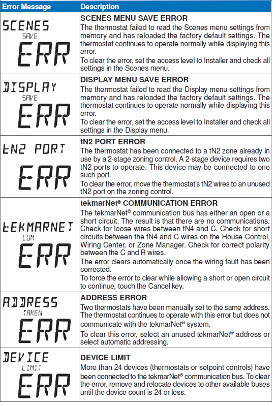
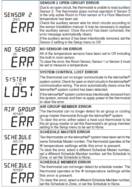
| ERROR HISTORY 1 THROUGH 5
Displays a history of the last 5 errors that have occurred on the thermostat in the past 30 days. Touch Enter to manually clear the error code. |
|
| Access Level: Installer | Range: See Troubleshooting section |
| Conditions: An error must have occurred in order to view in the error history. | Default: Not applicable |
Setup Menu (1 of 2)
| Setup Menu (1 of 2) | |
| Setting | Display |
| SENSOR 1
Select to the type of sensor connected to auxiliary sensor input 1. |
|
| Access Level: Installer | Range: OFF, ROOM, FLOR (floor), OUT (outdoor) |
| Conditions: Always available. | Default: OFF |
| SENSOR 2
Select to the type of sensor connected to auxiliary sensor input 2. |
|
| Access Level: Installer | Range: OFF, ROOM, FLOR (floor) |
| Conditions: Always available. | Default: OFF |
| ROOM SENSOR
Select whether the built-in room temperature sensor is on or off. |
|
| Access Level: Installer | Range: OFF or ON |
| Conditions: Only available when Sensor 1 or Sensor 2 is set to Room or Floor. | Default: ON |
| W1 TERMINAL UNIT
Select the terminal unit type of the first stage of heat W1. CTRL = Same as on tekmarNet® system control. HRF1 = High mass hydronic radiant floor HRF2 = Low mass hydronic radiant floor CONV = Fin-tube convectors COIL = Fan coil OTHR = Other than hydronic heating |
|
| Access Level: Installer | Range: CTRL, HRF1, HRF2, CONV, COIL, OTHR |
| Conditions: Only available when a tekmarNet® system control is connected. | Default: CTRL |
| W1 PUMP
Select whether the primary or mix system pump on a tekmarNet® system control should operate while the first stage of heat W1 is operating. |
|
| Access Level: Installer | Range: OFF or ON |
| Conditions: Only available when a tekmarNet® system control is connected and the Setup menu setting W1 TERM is set to CTRL, HRF1, HRF2, CONV, or COIL. |
Default: ON |
| Setup Menu (2 of 2) | |
| Setting | Display |
| W1 THERMAL MOTOR
Select whether the first stage of heat W1 operates a thermally actuated zone valve (wax actuator). When set to ON, there is a 3 minute delay before operating the pump and any heat sources. |
|
| Access Level: Installer | Range: OFF or ON |
| Conditions: Setup menu setting W1 TERM is set to CTRL, HRF1, HRF2, CONV, or COIL. | Default: OFF |
| W CYCLES PER HOUR
Select the number of heating cycles per hour. SYNC = Synchronize thermostats to a 20 minute cycle. AUTO = Automatic cycles per hour to minimum temperature swings. |
|
| Access Level: Installer | Range: SYNC, AUTO, 2 to 12 |
| Conditions: Setup menu setting W1 TERM is set to OTHR (other) or the thermostat is not connected to
a tekmarNet® system control. |
Default: SYNC |
| BASELOAD
Select the level of radiant floor baseload heating. This warms the floor so that solar gain and / or air heating systems do not cause cold floors. |
|
| Access Level: Installer | Range: OFF, LOW, MED, HIGH |
| Conditions: Only available when a tekmarNet® system control is connected and the Setup menu setting W1 TERM is set to HRF1 or HRF2 and SENSOR 1 or 2 is not set to FLOR (floor). |
Default: OFF |
| AIR GROUP MEMBER
Select if the thermostat is a member of an air group or cooling group. |
|
| Access Level: Installer | Range: NONE, 1 to 16 |
| Conditions: The thermostat must be connected to other thermostats using tekmarNet®. | Default: NONE |
Sequence of Operation
Heating Operation
Set Heat Temperature
When using only a room temperature sensor, the thermostat operates the heating system to maintain the Set Heat Room temperature. When using only a floor temperature sensor, the thermostat operates the heating system to maintain the Set Heat Floor temperature. In this case, the thermostat does not try to control the air temperature. This is ideal for bathrooms and some kitchen applications where the customer wants their feet to feel warm on the floor. This is also ideal for garages so that the heating system is not affected by the opening of the garage door in cold outdoor weather. When using both a room and a floor temperature sensor, the thermostat always maintains the Floor Minimum temperature, even when the air temperature is satisfied. When the air temperature is below the Set Heat Room temperature, the thermostat operates the heating system to maintain the Set Heat Room temperature. The floor is never heated above the Floor Maximum setting in order to protect the floor covering. Suggested Floor Maximum settings are 90°F (32°C) for tile, stone, or concrete floors and 85°F (29°C) for wood floors. The “Heat On” symbol is shown on the display when the thermostat is heating.
Room Minimum and Maximum
Room Minimum and Maximum temperature settings are available in the Set Temp menu. These allow the installer to select start and stop limits for the temperature setting for the User and Limited access levels. This is useful in commercial installations and child / guest bedrooms where availability of the full temperature setting range may not be desirable.
Warm Weather Shut Down
When the outdoor air temperature exceeds the Warm Weather Shut Down (WWSD) setting on the tekmarNet® main control, the heating system is shut off.
Radiant Floor Baseload
When the terminal unit is selected to be a Hydronic Radiant Floor (HRF1 or HRF2) and no floor temperature sensor is installed, the thermostat has option to provide baseload heating. This allows the radiant floor to be heated even though the room air temperature is satisfied. This is useful in areas where a radiant floor heating zone is overlapped by an air heating system. The radiant floor heating is overwhelmed by the quick heat up rate of the air heating system, resulting in a radiant floor heating zone that rarely turns on. The radiant baseload option allows the radiant floor to counteract the air heating system by heating the floor at a reduced output even when the room air temperature is satisfied. This is also useful in areas that experience large solar gains through windows. The radiant baseload is automatically shut off in the summer by the warm weather shut down feature
Freeze Protection
The thermostat operates the heat whenever the room or floor temperature falls below 40°F (4.5°C) even when the mode is set to off.
Exercising
When connected to a tekmarNet® system control, the thermostat exercises the heat relay for 10 seconds every 3 days. Exercising helps prevent zone valves or zone pumps from failing due to precipitate buildup. During exercising, the thermostat shows “TEST” on the display.
Flushing
The flushing feature is for open-loop systems that use a domestic hot water tank as a heat source. Flushing ensures that fresh potable water is circulated through the system once each day. If the thermostat is connected to a tekmarNet® system control with the Flushing feature turned on, the thermostat display will display “FLUSHING” for the duration of the flushing operation.
Hydronic System Supply Pump
When connected to a tekmarNet® system control, the thermostat’s W1 Pump setting affects how the primary pump or mix pump on the system control operates. When connected to the boiler bus, the boiler system or primary pump is operated. When connected to the mix bus, the mix system pump is operated. If the thermostat operates a motorized or thermal motor zone valve, the W1 Pump setting should be set to On. If the thermostat operates a thermal motor (wax actuator) zone valve, set the W1 Thermal Motor setting to On. This provides a three minute delay to allow the zone valve to open before the primary or mix pump is turned on. In special applications with multiple zoning manifolds, the W1 Pump setting can be set to Off. This allows a Zone Group Pump located on the Zone Manager, or Wiring Center to operate the pump for the manifold.
DHW Tank Priority
When a tekmarNet® system control is heating an indirect Domestic Hot Water (DHW) tank, the thermostat may shut off the heating zones to allow the DHW tank to recover quickly. This is determined by the DHW priority of the tekmarNet® system control
Air Group Operation
In order to prevent heating and cooling at the same time, this thermostat can operate together with other thermostats on a tekmarNet® system to form an air group. On older model thermostats the air group functionality was previously described as a cool group. In an air group, one thermostat is assigned as the air group master. The air group master operates the cooling equipment for the group. This thermostat can be set to be a member of the air group. When operating as a air group, the air temperature readings of all the air group member thermostats are communicated to the air group master thermostat and an average temperature is determined. When the air group master is in cooling operation, the air group member thermostats do not operate the heating system for air heating. If the Set Heat Room temperature is adjusted while the air group is cooling, COOL is flashed on the display to alert the user that the air group cooling system is presently on and heating is not available. Once the cooling system shuts off, heating is available if required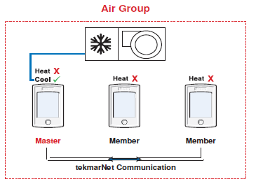
Time Clock
The thermostat includes a time clock that is automatically visible in the Home menu when a programmable schedule is used. If the schedule is not used, the user has the option to select whether the time is shown in the Home menu. During a loss of power, the thermostat continues to keep the correct time and date for at least 4 hours. If the power is off for more than 4 hours, the user will need to set the time. The thermostat supports automatic update for daylight savings time. Simply set Daylight Save to On together with the correct day, month, and year and the time is automatically updated each spring and fall. When connected to a tekmarNet® system, adjustment of the time on one thermostat updates all connected thermostats. This option can be disabled by selecting the Local Network Group setting to be On.
Temperature Adjustment
Permanent Adjustment – No Schedule
When no programmable schedule is used, touch the up or down arrows to permanently set the “Set Heat” temperature. This thermostat is capable of controlling the air or floor temperature. When set to control the floor temperature alone, the display will show “Floor” instead of “Room”.
Permanent Adjustment – With Schedule
When a programmable schedule is used, there are two room heating temperatures available, one for the time period and another for the time period. When touching the up or down arrows to change the temperature, only the temperature for the current time period is changed.
- To adjust the temperature for both time periods, press and hold the Home button for 3 seconds to enter the programming menu.
- Enter the “SET TEMP” menu to adjust the following settings:
- Set Heat Room (air heating or air heating with floor sensor)
- Set Heat Room (air heating or air heating with floor sensor)
- Set Heat Room AWAY (air heating or air heating with floor sensor)
- Floor Min (air heating with floor sensor)
- Floor Min (air heating with floor sensor)
- Set Heat Floor (floor heating sensor only)
- Set Heat Floor (floor heating sensor only)
Temporary Hold
Temporary hold allows a user to change the temperature for a period of time and then automatically return to the permanent temperature setting. This is especially useful in commercial buildings that are in use for short amounts of time. When selected, touching the up or down arrows changes the temperature for either 3, 6, 9 or 12 hours. If the thermostat is using a schedule, ‘Schd’ provides a temporary hold until the next schedule event time. After the temporary hold time expires, the thermostat returns to normal operation. By default, the temporary hold feature is off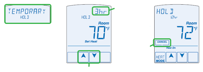
Programmable Schedules
Lowering the room temperature setting reduces the amount of fuel required to heat the building resulting in energy savings. When operating on a programmable schedule, a or a symbol is shown in the home menu. The or indicates the current operating temperature.
All schedules are stored in permanent memory and are not affected by a loss of power.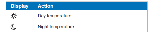
This thermostat can operate on a programmable schedule in order to automatically lower the room temperature setting. Options include:
- Turning off the schedule (OFF)
- Operate a schedule that applies only to this thermostat zone (ZONE)
- The ability to operate one of the four system-wide schedules as a master (Schedule Master 1 through 4*)
- Join one of the four system-wide schedules as a member (Schedule Member 1 though 4*)
- Requires the thermostat to be connected to a tekmarNet® system.
- Once the type of schedule has been selected, the thermostat can support schedules that have either:
- 2 events per day
- 4 events per day
- Schedules with four events per day are common for residential use while two events per day are common for commercial installations.
- The schedules can be repeated every:
- 24 hours
- 7 days (week)
- A 7 day schedule allows a unique time to be set to change the temperature for each day of the week.
The schedule also includes a “SKIP” option that allows the programmable schedule to skip a temperature change and remain at the previous temperature setting. The “SKIP” setting can be found between 11:50 PM (23:50 hours) and 12:00 AM (0:00 hours). When a programmable schedule is selected, there is a time delay for the room to warm up from the temperature to the temperature. The thermostat has the option to use Optimum Start to predict the heat up rate of the room. When Optimum Start is set to On, the heating is started in advance to allow the room to reach the Set Room temperature at the time set in the programmable schedule.
Scenes (System Override
Scenes provide an easy way to save energy while away on vacation, or override a programmable schedule when plans change.
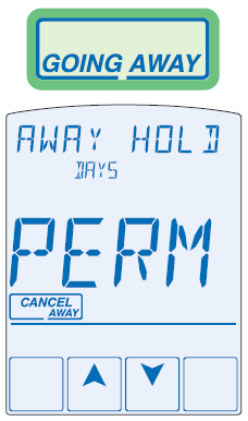
Away Key
This thermostat includes an Away Key to quickly turn down the heating temperature on all thermostats and suspend heating the domestic hot water tank to maximize energy savings. To turn on the Away Key, go to the Scene menu
To activate the Away scene, touch “Going Away” on the screen.
- Select PERM (permanent) or a number of days using the or arrow. Range is 1 to 180 days.
- Press the home button to accept the setting or leave the screen untouched for several seconds.
- “Scene Away” is displayed on the home screen until the number of days expires.
- Touch “Cancel Away” to cancel at any time.
Additional Scenes
Additional energy saving scenes are available when a User Switch or Gateway is installed. A complete listing of each scene is shown below
| Scene Number | Scenes
= None Operation |
Scenes
= Away Operation |
Scenes
= All Operation |
Scenes
= Guest Operation |
| 1 | Permanent or Schedule | Permanent or Schedule | Permanent or Schedule | Permanent |
| 2 | Scene 1 | Away | Away | Away |
| 3 | Scene 1 | Scene 1 | Permanent | Permanent |
| 4 | Scene 1 | Scene 1 | Configurable | Permanent |
| 5 | Scene 1 | Scene 1 | Permanent or Schedule | Permanent or Schedule |
| 6 | Scene 1 | Scene 1 | Temporary 3 Hours | Permanent |
| 7 | Scene 1 | Scene 1 | Temporary 4 Hours | Permanent |
| 8 | Scene 1 | Scene 1 | Temporary 8 Hours | Permanent |
Recommendation on How to Use Scenes
Choosing how to use scenes depends on the needs and lifestyle of the customer using the building.
Multi-Tenant Apartments
Scenes should be disabled (None) in multi-tenant buildings where the each occupant has differing heating requirements.
Residential Homes
Some residential customers may not require scenes, in which case, scenes can be disabled (None). Home owners that wish to save on energy costs should consider using the Away scene to save energy while away from the property (example: vacation or holidays). The use of the Guest scene is useful in residential applications where there are a number of spare bedrooms that are occupied on an infrequent basis. Each spare bedroom would be setup to operate on the Guest scene. The remaining thermostats can be setup to operate on the None, Away or All scene configuration. Normally, the spare bedrooms would operate at the moon temperature settings. When guests arrive, scene 5 can be activated through the use a User Switch or Gateway. The spare bedroom then operates at the temperature settings or operates on a programmable schedule if a schedule has been setup. When guests depart, the scene can be changed back to scene 1 and the spare bedrooms resume operation at the temperature settings.
Commercial Buildings
Commercial buildings are typically in use on a predictable schedule and normally the building can operate in scene 1. In order to accommodate staff working overtime or cleaning staff, a 3 or 8 hour temporary override is available when installed in conjunction with a User Switch or Gateway. In these cases, the thermostats should be setup to use the All scene configuration. At the touch of a button, the whole building changes from operating on a programmable schedule (typically at the temperature setting when not occupied) to operating at the temperature settings for 3 hours (scene 6) or 8 hours (scene 8). After the timer counts down and expires, the scene changes back the previous scene.
Secondary Temperature Display Section H
This thermostat can display the outdoor or floor temperature in the upper right hand corner of the display. Touch the upper right hand corner to toggle the item currently displayed. Display of the floor or outdoor temperature requires a connection to an outdoor or floor temperature sensor, or the thermostat is connected to a tekmarNet® system that includes an outdoor sensor. The reading of the outdoor sensor connected directly to the thermostat takes precedence over any outdoor sensor reading available on the tekmarNet® system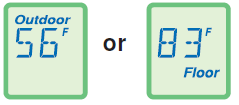
Access Levels Section I
The thermostat Toolbox menu supports four access levels: Installer (INST), User (USER), Limited (LTD), and Secure (SEC). The access level can be adjusted when the thermostat is unlocked. There are two locations to lock the thermostat:
- Locally on the back of the thermostat using the Lock switch
- Globally on the tekmarNet® system control using the Lock switch or Access level (if installed)
Both the local and global lock settings must be set to unlock before the thermostat access level is adjustable. The selection of the access level is dependent on the use of the building and the type of occupants.
- Installer – Suitable for HVAC installers only. Times out to User access level after 24 hours.
- User – Suitable for most residential homeowners.
- Limited – Suitable for rental properties or commercial buildings where some level of temperature adjustment is required.
- Secure – Suitable for schools, churches, and other public buildings where temperature adjustment is not desired.
tekmarNet® Address Section J
When connected to a tekmarNet® system, each thermostat will be automatically given an address. The address is useful as a troubleshooting tool to locate thermostats with errors and also allows room naming on a Gateway. The address consists of the bus water temperature followed by the thermostat device number. Available buses are b (boiler), 1, 2 and 3. Device numbers range from 01 to 24. If the thermostat is used without a tekmarNet® system control, the bus number is not shown. When using the thermostat together with a Gateway, it is important that each address be changed to be manually set. This allows each thermostat to be named on the Gateway. If two thermostats are manually set to the same address, an error message will appear. The error remains until one of the addresses is manually changed to a vacant address or to Auto. It is highly recommended to keep a documented list of thermostat addresses. This is extremely helpful when troubleshooting errors. The tekmarNet® system control will display the addresses of thermostat’s that have errors. By referring to the address documentation, it simplifies the process to locate and correct error messages
Screen Clean Menu Section K
Entering the Screen Clean menu gives you 30 seconds to clean the thermostat and display with a moist cloth. Do not use solvents to clean the thermostat
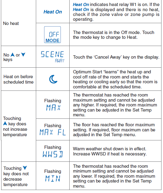
Troubleshooting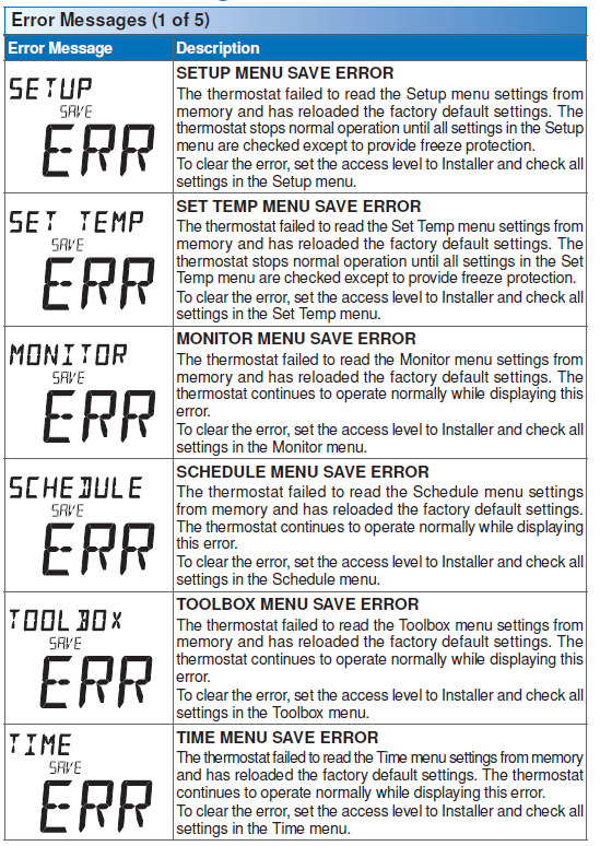
FAQS
Technical Data
| tekmarNet® Thermostat 552; One Stage Heat | |
| Packaged weight | 0.8 lb. (350 g) |
| Enclosure | White ABS / PC plastic |
| Dimensions | 5” H x 3-1/4” W x 15/16” D (127 x 82 x 23 mm) |
| Approvals | Meets Class B: ICES & FCC Part 15 |
| Ambient conditions | Indoor use only, 32 to 122°F (0 to 50°C), RH ≤90% non-condensing |
| Power supply | 24 V ±10%, 50/60 Hz, 1.8 VA Standby, 56 VA fully loaded, NEC
/ CEC Class 2 |
| W1 Relay | 24 V (ac) 2 A |
| Sensors: | NTC thermistor, 10 kΩ @ 77°F (25°C ±0.2°C) ß=3892 |
| – Included | None |
| – Optional | tekmar type # 070, 071, 072, 073, 076, 077, 078, 079, 082, 084 |
Warranty
Limited Warranty and Product Return Procedure
Limited Warranty The liability of tekmar under this warranty is limited. The Purchaser, by taking receipt of any tekmar product (“Product”), acknowledges the terms of the Limited Warranty in effect at the time of such Product sale and acknowledges that it has read and understands same. The tekmar Limited Warranty to the Purchaser on the Products sold hereunder is a manufacturer’s passthrough warranty which the Purchaser is authorized to pass through to its customers. Under the Limited Warranty, each tekmar Product is warranted against defects in workmanship and materials if the Product is installed and used in compliance with tekmar’s instructions, ordinary wear and tear excepted. The passthrough warranty period is for a period of twenty-four (24) months from the production date if the Product is not installed during that period, or twelve (12) months from the documented date of installation if installed within twenty-four (24) months from the production date.
The liability of tekmar under the Limited Warranty shall be limited to, at tekmar’s sole discretion: the cost of parts and labor provided by tekmar to repair defects in materials and / or workmanship of the defective product; or to the exchange of the defective product for a warranty replacement product; or to the granting of credit limited to the original cost of the defective product, and such repair, exchange or credit shall be the sole remedy available from tekmar, and, without limiting the foregoing in any way, tekmar is not responsible, in contract, tort or strict product liability, for any other losses, costs, expenses, inconveniences, or damages, whether direct, indirect, special, secondary, incidental or consequential, arising from ownership or use of the product, or from defects in workmanship or materials, including any liability for fundamental breach of contract. The pass-through Limited Warranty applies only to those defective Products returned to tekmar during the warranty period. This Limited Warranty does not cover the cost of the parts or labor to remove or transport the defective Product, or to reinstall the repaired or replacement Product, all such costs and expenses being subject to Purchaser’s agreement and warranty with its customers. Any representations or warranties about the Products made by Purchaser to its customers which are different from or in excess of the tekmar Limited Warranty are the Purchaser’s sole responsibility and obligation. Purchaser shall indemnify and hold tekmar harmless from and against any and all claims, liabilities and damages of any kind or nature which arise out of or are related to any such representations or warranties by Purchaser to its customers. The pass-through Limited Warranty does not apply if the returned Product has been damaged by negligence by persons other than tekmar, accident, fire, Act of God, abuse or misuse; or has been damaged by modifications, alterations or attachments made subsequent to purchase which have not been authorized by tekmar; or if the Product was not installed in compliance with tekmar’s instructions and / or the local codes and ordinances; or if due to defective installation of the Product; or if the Product was not used in compliance with tekmar’s instructions.
THIS WARRANTY IS IN LIEU OF ALL OTHER WARRANTIES, EXPRESS OR IMPLIED, WHICH THE GOVERNING LAW ALLOWS PARTIES TO CONTRACTUALLY EXCLUDE, INCLUDING, WITHOUT LIMITATION, IMPLIED WARRANTIES OF MERCHANTABILITY AND FITNESS FOR A PARTICULAR PURPOSE, DURABILITY OR DESCRIPTION OF THE PRODUCT, ITS NON-INFRINGEMENT OF ANY RELEVANT PATENTS OR TRADEMARKS, AND ITS COMPLIANCE WITH OR NON-VIOLATION OF ANY APPLICABLE ENVIRONMENTAL, HEALTH OR SAFETY LEGISLATION; THE TERM OF ANY OTHER WARRANTY NOT HEREBY CONTRACTUALLY EXCLUDED IS LIMITED SUCH THAT IT SHALL NOT EXTEND BEYOND TWENTY-FOUR (24) MONTHS FROM THE PRODUCTION DATE, TO THE EXTENT THAT SUCH LIMITATION IS ALLOWED BY THE GOVERNING LAW. Product Warranty Return Procedure All Products that are believed to have defects in workmanship or materials must be returned, together with a written description of the defect, to the tekmar Representative assigned to the territory in which such Product is located. If tekmar receives an inquiry from someone other than a tekmar Representative, including an inquiry from Purchaser (if not a tekmar Representative) or Purchaser’s customers, regarding a potential warranty claim, tekmar’s sole obligation shall be to provide the address and other contact information regarding the appropriate Representative.
tekmar
- Product design, software and literature are Copyright ©2014 by tekmar Control Systems Ltd.,
- A Watts Water Technologies Company.
- Head Offi ce: 5100 Silver Star Road, Vernon, B.C.
- Canada V1B 3K4, 250-545-7749,
- Fax. 250-545-0650
- Web Site: www.tekmarControls.com
Reference
Download Manual:
tekmar 552_D Programmable Thermostat Installational Manual
Leave a Reply