
SIEMENS RDU340 Flush-mount Room Thermostat

Flush-mounted room thermostat
- for CAV / VAV heating and cooling systems
- for AHU systems
- for universal heating and cooling systems
SPECIFICATION
- Modulating PI control
- Control depending on the room or the return air temperature
- Output for a DC 0…10 V actuator and AC 230 V electric heater (ON/OFF)
- Automatic or manual heating/cooling changeover
- Operating modes: Comfort, Economy, and Protection
- Two multifunctional inputs for keycard contact, external sensor, etc.
- Adjustable commissioning and control parameters
- Minimum and maximum setpoint limitation
- Adjustable minimum and maximum limitation for airflow signal DC 0…10 V
- Output signal inversion as an option (DC 0…10 V à DC 10…0 V)
- Mounting on recessed square conduit box, 60.3 mm fixing centers
- AC 24 V operating voltage
- User and parameter settings can be retained or restored with power loss
Use
Control of the room temperature in individual rooms of ventilation or air conditioning plants that are:
- Heated or cooled by a single duct.
- Heated or cooled by a single duct with an electric heater.
The RDU340 is suitable for use with VAV systems in connection with the VAV compact controller types G…B181.1E/3.
The RDU340 can also be used as an AHU temperature controller in connection with valve actuators, as well as for universal heating and cooling applications with DC 0…10 V actuators.
The RDU340 controls
- One DC 0…10 V actuator
- One DC 0…10 V actuator and AC 230V 1-stage electric heater
Use in systems with:
- Heating or cooling mode
- Automatic heating/cooling changeover
- Manual heating/cooling changeover
- Heating and cooling single duct (single duct with electric heater)
Functions
- Maintain room temperature via built-in temperature sensor or external room temperature / return air temperature sensor
- Automatic or manual changeover between heating and cooling mode
- Select applications via DIP switches
- Select operating mode via the operating mode button on the thermostat
- Display current room temperature or setpoint in °C and/or °F.
- Minimum and maximum setpoint limitation
- Key lock (automatic and manual)
- Two multifunctional inputs, freely selectable for:
- Operating mode switchover contact (key card)
- Automatic heating/cooling changeover sensor
- External room temperature or return air temperature sensor
- Dewpoint sensor.
- Electric heater enable
- Alarm input
- Minimum and maximum limitation of air flow signal DC 0…10 V
- Reload factory settings for commissioning and control parameters
Applications
Prior to snapping the front panel to the base, use the DIP switches on the inner side of the front panel to commission the thermostat’s applications and the behavior of the output signal.
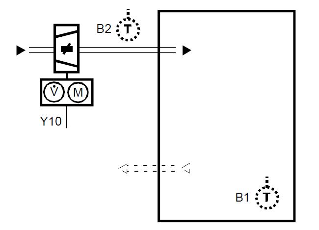
Application and output signal, DIP switches, diagram
- Single duct,
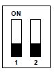 Heating or cooling Modulating, DC 0…10 V output signal normal (Factory setting)
 - Single duct, Heating or cooling Modulating, DC 0…10 V output signal inverted
- Single duct with electrical heater, Cooling and heating, with auxiliary heater Modulating, DC 0…10 V output signal normal Note: on-off electrical heater
- Single duct with electrical heater, Cooling and heating, with auxiliary heater DC 0…10 V output signal inverted Note: on-off electrical heater

V1 Heating or heating/cooling valve actuator
B1 Return air temperature sensor or external room temperature sensor (optional)
E1 Electric heater
B2 Changeover sensor (optional)
Note
During startup, the thermostat reloads the control parameter factory settings after each DIP switch settings change
Type summary
|
Product no. |
Operating voltage |
Control output | Backlit LCD | Infrared receiver | Housing color | ||
|
3-pos |
on/off |
DC 0…10 V |
|||||
| RDU340 | AC 24 V | — | white | ||||
Equipment combinations
DC 0…10 V actuator
| Designation | Product no. | Data Sheet*) | |
| Cable temperature sensor or changeover sensor, cable length 2.5 m
NTC (3 kn at 25 °C) |
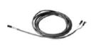 |
QAH11.1 |
1840 |
| Room temperature sensor NTC (3 kn at 25 °C) |  |
QAA32 | 1747 |
| Electrical actuator, DC 0…10 V (for radiator valve) |  |
SSA61… |
4893 |
| Electrical actuator, DC 0…10 V (for 2- and 3-port valves / V…P45) | 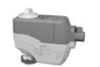 |
SSC61… | 4895 |
| Electrical actuator, DC 0…10 V (for small valve 2.5 mm) |  |
SSP61… | 4864 |
| Electrical actuator, DC 0…10 V (for small valves 5.5 mm) | 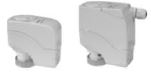 |
SSB61… | 4891 |
| Electrical actuator, DC 0…10 V (for CombiValves VPI45) |  |
SSD61… | 4861 |
|
Electromotoric actuator, DC 0…10 V (for valves 5.5 mm) |
 |
SQS65… |
4573 |
| Electrothermal actuator,
AC 24 V, NC, DC 0…10 V, 2 m (for radiator valves and small valve 2.5 mm) |
 |
STA63 |
4884 |
| Electrothermal actuator,
AC 24 V, NO, DC 0…10 V, 2 m (for radiator valves and small valve 2.5 mm) |
 |
STP63 |
4884 |
|
DC 0…10 V damper / valve actuator |
 |
GQD161… | 4605 |
 |
GDB161… |
4634 |
|
| GLB161… | |||
 |
GMA161… | 4614 | |
|
GEB161… |
4621 |
||
 |
GCA161… | 4613 | |
| GBB161… |
4626 |
||
| GIB161… | |||
|
VAV compact controller |
 |
GDB181.1E/3 |
3544 |
The documents can be downloaded from http://siemens.com/bt/download
Accessories
| Designation | Product no. | Data Sheet*) |
| Changeover mounting kit (50 pcs/package) | ARG86.3 | N3009 |
| Plastic mounting spacer for flush mounted thermostats for increasing the headroom in the
conduit box by 10 mm |
ARG70.3 |
N3009 |
| Conduit box for flush mounted thermostat | ARG71 / S55770-T137 | N3009 |
The documents can be downloaded from http://siemens.com/bt/download.
Ordering
When ordering, indicate both product number and designation: E.g. RDU340 room thermostat
Order valve actuators separately
Mechanical design
The thermostat consists of 2 parts:
- Front panel accommodating the electronics, operating elements and built-in room temperature sensor.
- Mounting base with the power electronics.
The rear of the mounting base contains the screw terminals. The base fits on a square conduit box with 60.3 mm fixing centers. Slide the front panel in the mounting base and snap on.
Operation and settings
- Operating mode selector / Protection
- Adjust setpoint and control parameters
Display
- Operating mode
 Protection
 Comfort
 Economy
- Display room temperature, setpoints and control parameters.
 Symbol used to display the current room temperature
- Heating/cooling mode
 Cooling mode
 Heating mode,
 Electric heater active
- Additional user information
- Key lock active
- Condensation in room (dewpoint sensor active)
- Indicate fault or reminder
Mounting and installation
Mount the room thermostat on a recessed square conduit box with 60.3mm fixing centers. Do not mount on a wall in niches or bookshelves, behind curtains, above or near heat sources, or exposed to direct solar radiation. Mount about 1.5 m above the floor.
Mounting
- Devices must be mounted on clean, dry indoor place without direct airflow from a heating / cooling device, and not be exposed to dripping or splashing
- In case of limited space in the conduit box use the mounting bracket ARG70.3 to increase the headroom by 10 mm
Wiring
See the mounting instructions M3078 enclosed with the thermostat.
- Comply with local regulations to wire, protection and earth the thermostat.
- The power supply line must have a circuit breaker with a rated current of no more than 10 A. For US installations use Class 2 rated power supplies
Warning!
No internal line protection for supply lines to external consumers (Y10, Y21)
Risk of fire and injury due to short-circuits!
- Adapt the line diameters as per local regulations to the rated value of the installed overcurrent protection device.
- Isolate the cables of SELV inputs X1-M/X2-M if the conduit box carries AC 230 V mains voltage.
- Inputs X1-M or X2-M of different units (e.g. summer/winter switch) may be connected in parallel with an external switch. Consider overall maximum contact sensing current for switch rating.
- No metal conduits
- No cables provided with a metal shield
- Disconnect from supply before opening the cover
Commissioning
- Set the thermostat application via the DIP switches before snapping the front panel on the mounting base.
- After power is applied, the thermostat carries out a reset during which all LCD segments flash indicating that the reset was correct. After the reset, which takes about 3 seconds, the thermostat is ready for commissioning by qualified HVAC staff. The control parameters of the thermostat can be set to ensure optimum performance of the entire system (see basic documentation P3078).
Note
After powerfail the thermostat restarts in the same mode as before.
Control sequence
The control sequence may need to be set via parameter P01 depending on the application. The factory setting for the single duct application is “Cooling only”.
Calibrate sensor
Recalibrate the temperature sensor if the room temperature displayed on the thermostat does not match the room temperature measured (after min. 1 hour of operation). To do this, change parameter P05.
Setpoint and range limitation
We recommend to review the setpoints and setpoint ranges (parameters P08…P12) and change them as needed to achieve maximum comfort and save energy
Disposal
The device is considered electrical and electronic equipment for disposal in terms of the applicable European Directive and may not be disposed of as domestic garbage.
- Dispose of the device through channels provided for this purpose.
- Comply with all local and currently applicable laws and regulations
Technical data


Connection terminals

- G, G0 Operating voltage thermostat AC 24 V
- L Operating voltage for electric heater AC 230 V
- Y21 Control output for electric heater
- Y10 Control output for DC 0…10 V actuator
- X1, X2 Multifunctional input for temperature sensor (e.g. QAH11.1) or switch
- M Measuring neutral for sensor and switch
Connection diagrams
Application:
Single duct in VAV/CAV Heating or cooling for universal or AHU
- N1 Room thermostat RDU340
- V1 VAV / CAV system, DC 0…10V actuator for heating or cooling
- S1 Operating mode switch-over contact (e.g. key card)
- B2 Heat/cool changeover sensor
Application:
Single duct with electric heater in VAV/CAV Heating and cooling with electric heater for universal or AHU
- N1 Room thermostat RDU340
- V1 VAV / CAV system, DC 0…10V actuator for heating or cooling
- E1 Electric heater
- S1 Operating mode switch-over contact (e.g. key card)
- B2 Heat/cool changeover sensor
Warning
- For US installations use Class 2 rated power supplies.
- For other installations use circuit breakers with rated current of no more than 10 A.
Dimensions

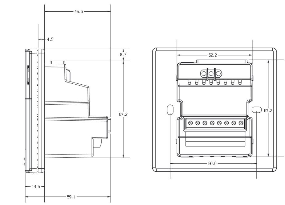
Dimensions in mm
© Siemens Switzerland Ltd, 2008 – 2019
Technical specifications and availability are subject to change without notice.
Issued by
Siemens Switzerland Ltd Smart Infrastructure Global Headquarters Theilerstrasse 1a CH-6300 Zug
Tel. +41 58 724 2424
www.siemens.com/buildingtechnologies
Siemens Smart Infrastructure
REFERENCE:
DOWNLOAD MANUALS:
SIEMENS RDU340 Flush-mount room thermostat Product Specifications Guide
![]()
SIEMENS RDU340 Flush-mount Room Thermostat Product Specifications Guide
Leave a Reply