
SIEMENS RDG400 Room Thermostat
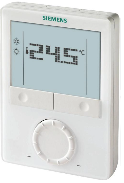
Wall-mounted room thermostat with LCD
for VAV heating and cooling systems
- Modulating PI control
- Control depending on the room or the return air temperature
- Output for DC 0…10 V actuator and auxiliary output On/Off, PWM or 3- position
- Automatic or manual heating/cooling changeover
- Operating modes: Comfort, Economy, and Protection
- 3 multifunctional inputs for keycard contact, external sensor, etc.
- Adjustable commissioning and control parameters
- Minimum and maximum setpoint limitation
- The minimum and maximum limit of airflow signal DC 0…10 V
- Output signal inversion as an option
- Operating voltage AC 24 V
- Backlit display
Use
The room thermostat is designed for the following types of systems: VAV systems via On/Off or modulating control outputs:
- Single-duct system
- A single-duct system with an electric heater
- Single-duct system and radiator/floor heating
- A single-duct system with a heating/cooling coil
Functions
- Room temperature control via built-in temperature sensor or external room temperature/return air temperature sensor
- Automatic or manual changeover between heating and cooling mode
- Selection of applications via DIP switches
- Selection of operating mode with the operating mode button on the thermostat
- Display of current room temperature or setpoint in °C and/or °F
- Minimum and maximum setpoint limitation
- Button lock (automatic or manual)
- 3 multifunctional inputs, freely selectable for:
- Operating mode switchover contact (keycard, window contact, etc.)
- Changeover sensor for automatic heating/cooling mode
- External room temperature or return air temperature
- Dewpoint sensor
- Electric heater enable
- Faults
- The minimum and maximum limit of airflow signal DC 0…10 V
- Floor heating temperature limit
- Reload factory settings for commissioning and control parameters
- Wizard function to select working temperature unit °C or °F
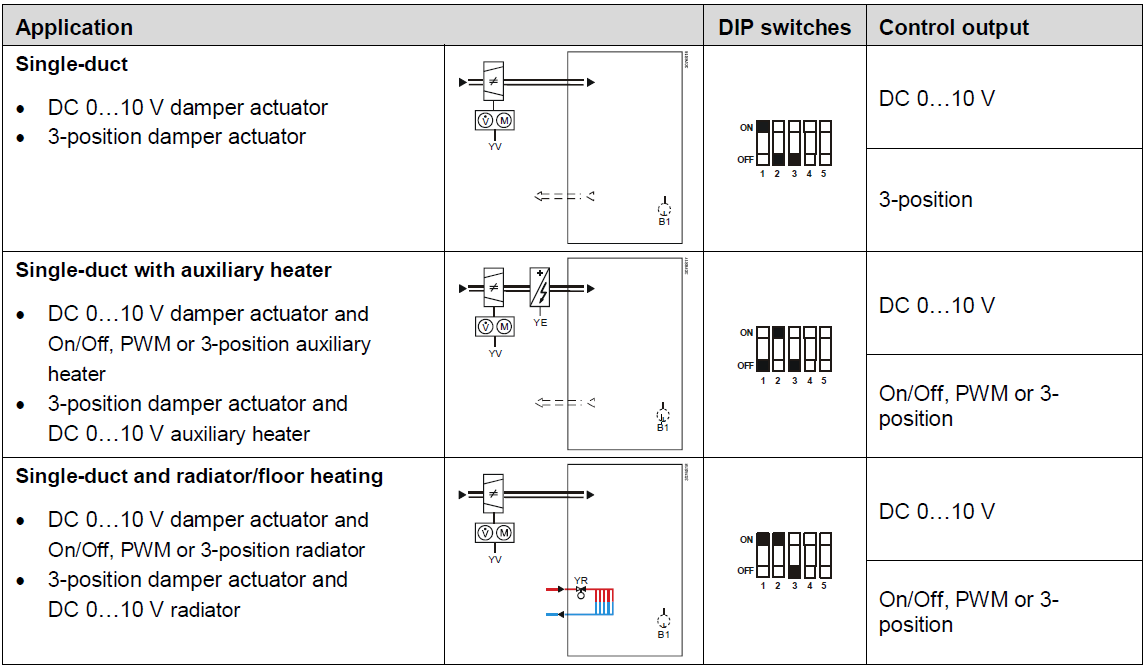
Applications
The thermostat supports the following applications, which can be configured via DIP switches at the rear of the unit. The control output for the damper actuator is either DC 0…10 V (factory setting) or 3-position (see parameter P47), and for the auxiliary heating/cooling output On/Off, PWM, 3-position or DC 0…10 V.

Type summary
| Product no. | Operating voltage | Number of control outputs | |||
| On/Off | PWM | 3-pos | DC 0…10 V | ||
| RDG400 | AC 24 V | 11) | 11) | 11) | 1 |
Equipment combinations
| Type of unit | Type reference | Data Sheet*) |
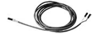
| Cable temperature sensor, cable
length 2.5 m (8 feet) NTC (3 kn at 25 °C (77 °F)) |
QAH11.1 |
1840 |
Room temperature sensor NTC (3 kn at 25 °C (77 °F)) |
QAA32 | 1747 |
Cable temperature sensor, cable length 4 m (13 feet) NTC (3 kn at 25 °C (77 °F)) |
QAP1030/UFH |
1854 |
Condensation detector/supply unit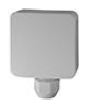 |
QXA2000/ QX2000 | 1542 |
Electrical actuator, DC 0…10 V (for radiator valve)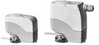 |
SSA61.. | 4893 |
Electrical actuator, DC 0…10 V (for 2 and 3 port valves/V..P45)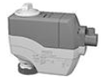 |
SSC61.. | 4895 |
Electrical actuator, DC 0…10 V (for small valve 2.5 mm (0.1″))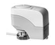 |
SSP61.. | 4864 |
Electrical actuator, DC 0…10 V (for small valves 5.5 mm (0.2″))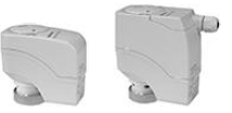 |
SSB61.. | 4891 |
| Electrical actuator, DC 0…10 V
(for Combi-valve VPI45) |
SSD61.. | 4861 |
Electromotoric actuator, DC 0…10 V (for valves 5.5 mm (0.2″))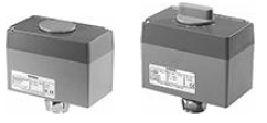 |
SQS65.. | 4573 |
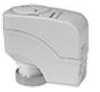
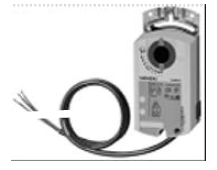
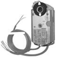
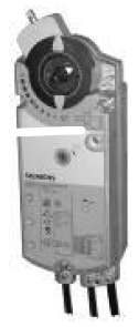
| DC 0…10 V damper actuator | 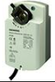 |
GQD161.. | 4605 |
 |
GDB161.. |
4634 |
|
| GLB161.. | |||
 |
GMA161.. | 4614 | |
| GEB161.. | 4621 | ||
 |
GCA161.. | 4613 | |
| GBB161.. |
4626 |
||
| GIB161.. | |||
VAV compact controller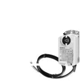 |
GDB181.1E/3 |
3544 |
|
| GLB181.1E/3 | |||
Electromotoric On/Off valve and actuator (only available in AP, UAE, SA and IN)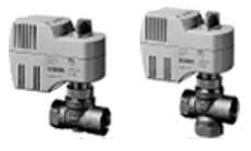 |
MVI../MXI.. |
4867 |
|
Electromotoric On/Off actuator 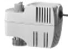 |
SFA71.. | 4863 | |
| Thermal actuator (for radiator valve) |
STA71.. | 4877 | |
Thermal actuator (for small valves 2.5 mm (0.1″))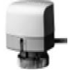 |
STP71.. | 4878 | |
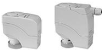
Electrical actuator, 3-position (for radiator valve)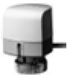 |
SSA81.. | 4893 | |
Electrical actuator, 3-position (for small valve 2.5 mm (0.1″))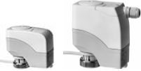 |
SSP81.. | 4864 | |
Electrical actuator, 3-position (for small valve 5.5 mm (0.2″)) |
SSB81.. | 4891 | |
| Electrical actuator, 3-position
(for Combi-valve VPI45) |
SSD81.. | 4861 | |
Electromotoric actuator, 3-position (for valves 5.5 mm (0.2″))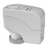 |
SQS85.. |
4573 |
|
Accessories
| Description | Product no. | Data Sheet*) |
| Changeover mounting kit (50 pcs/package) | ARG86.3 | 1840 |
| Adapter plate 120 x 120 mm for 4″ x 4″ conduit boxes | ARG70 | |
| The adapter plate 112 x 130 mm for surface wiring | ARG70.2 |
Ordering
- When ordering, please indicate product no. and description:
- For example RDG400 room thermostat
- Order valve actuators separately.
Mechanical design
The room thermostat consists of two parts:
- Plastic housing which accommodates the electronics, the operating elements and the room temperature sensor
- Mounting plate with the screw terminals
The housing engages in the mounting plate and is secured with 2 screws.
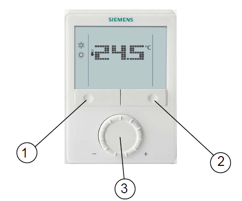
Operation and settings
- Operating mode selector/Esc
- Protection and Ok
- Rotary knob for setpoint and parameter adjustment
Display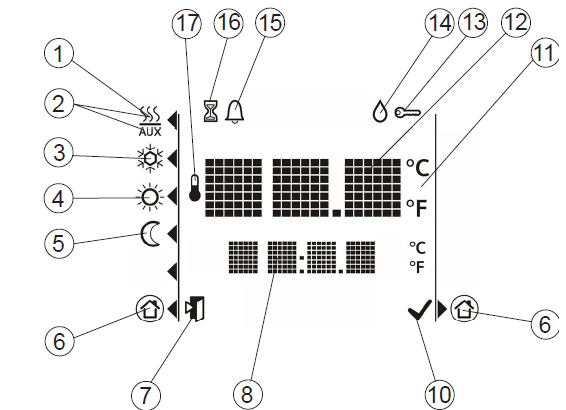
| # | Symbol | Description | # | Symbol | Description |
|
1 |
Heating mode | 10 | Confirmation of parameters | ||
|
2 |
 |
Heating mode
auxiliary heater on (2nd stage) |
11 |
Degrees Celsius Degrees Fahrenheit | |
|
3 |
Cooling mode | 12 | Digits for room temperature and setpoint | ||
|
4 |
Comfort mode | 13 | Button lock active | ||
|
5 |
Economy mode | 14 | Condensation in the room (dew point sensor active) | ||
|
6 |
Protection | 15 | Fault | ||
|
7 |
Escape |
16 |
Temporary timer function (visible when the operating mode is temporarily extended due to prolonged presence or absence) | ||
|
8 |
Digits for room temperature, setpoint, etc. | 17 | Indicates that room temperature is displayed |
Mounting and installation
Do not mount on a wall in niches or bookshelves, behind curtains, above or near heat sources, or exposed to direct solar radiation. Mount about 1.5 m (5 feet) above the floor.
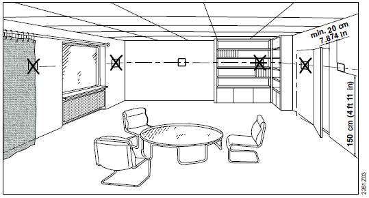
Mounting: The room thermostat must be mounted in a clean, dry indoor place and must not be exposed to drip or splash water.
Wiring
See Mounting Instructions (M3182) enclosed with the thermostat.
- Comply with local regulations to wire, protect and earth the thermostat. Warning!
No internal line protection for supply lines to external consumers (Y1, Y2) Risk of fire and injury due to short circuits! - Adapt the line diameters as per local regulations to the rated value of the installed overcurrent protection device.
- The power supply line must have a circuit breaker with a rated current of no more than 10 A. For US installations use Class 2-rated power supplies.
- Inputs X1-M, X2-M or D1-GND of different units (e.g. summer/winter switch) may be connected in parallel with an external switch. Consider the overall maximum contact sensing current for switch rating.
- Disconnect power supply before removing the thermostat from the mounting plate!
Commissioning
- Select the application via the DIP switches at the rear of the thermostat before fitting the front housing to the mounting plate.
- Power up the thermostat after successfully connecting the line power. The thermostat starts to reset and all LCD segments flash, indicating that the reset is correct.
After the reset, which takes about 3 seconds, the thermostat is ready for commissioning by qualified HVAC staff. The control parameters of the thermostat can be adjusted to ensure the optimum performance of the entire system (see Basic Documentation P3182).
Temperature unit selection wizard
The temperature unit selection wizard enables to select the preferred temperature unit display on the thermostat between °C and °F.
- Rotate the rotary knob to select the preferred temperature unit.
- Press the button
 (OK) to confirm the selection, and the thermostat goes to a normal operating page.
Notes
- Pressing the button
 (Esc) does not confirm the temperature unit selection.
 - If the temperature unit is not selected, °C is used by default.
Control sequence
- The control sequence may need to be set via parameter P01 depending on the application. The factory setting for the single-duct application is “Cooling only”.
Calibrate sensor
- Recalibrate the temperature sensor if the room temperature displayed on the thermostat does not match the room temperature measured. To do this, change parameter P05.
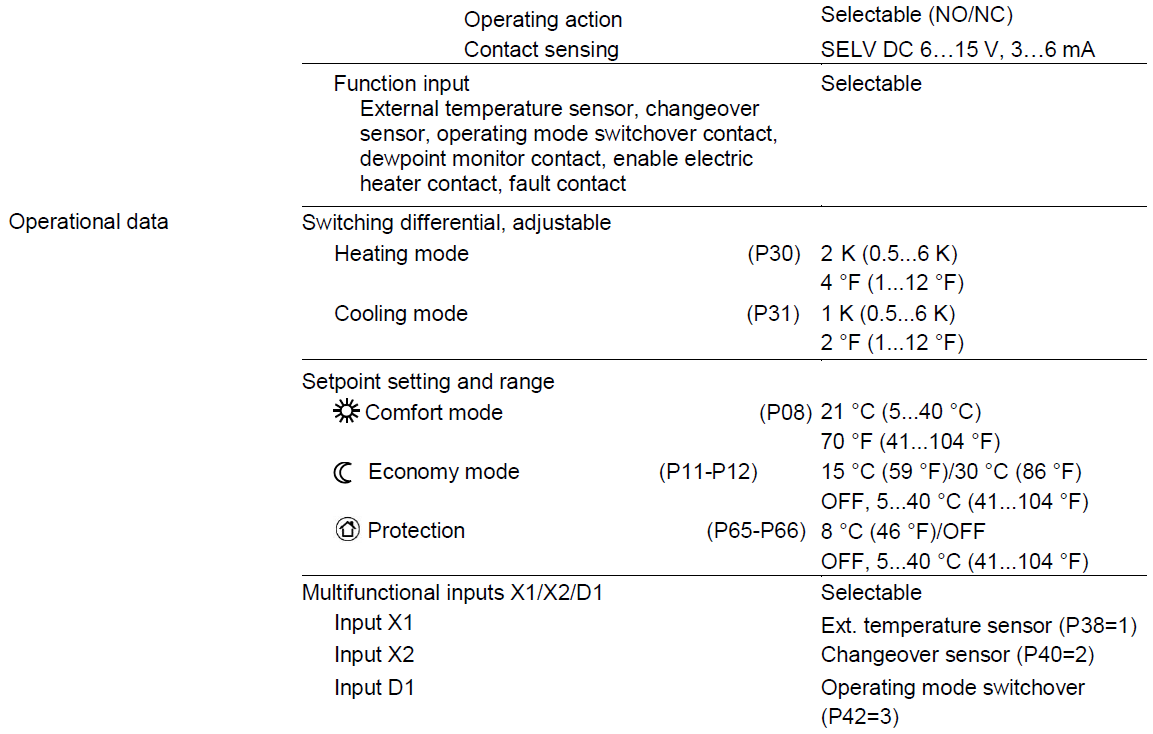
Setpoint and setpoint range limitation
- We recommend reviewing the setpoints and setpoint ranges (parameters P08…P12) and change them as needed to achieve maximum comfort and save energy.
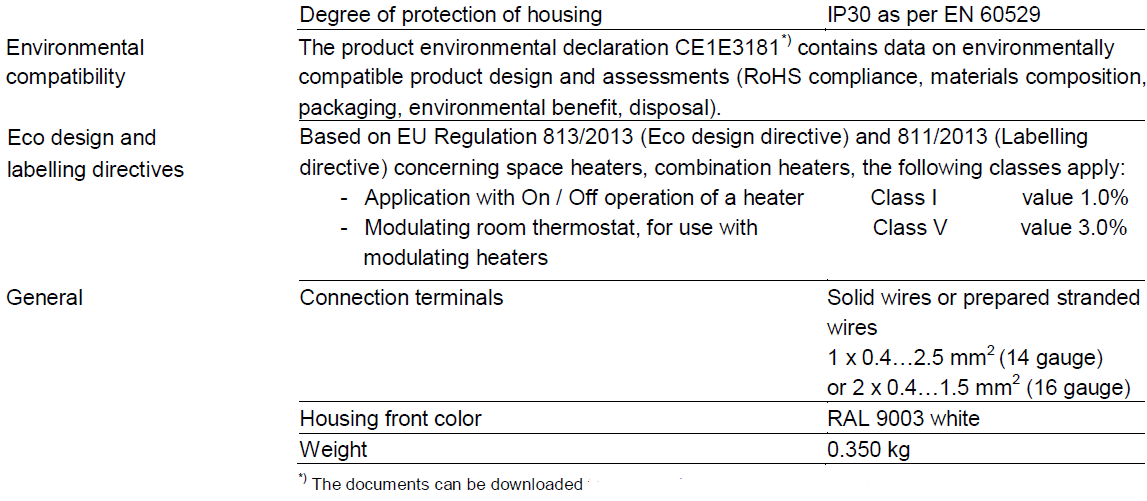
Disposal: The device is considered an electronic device for disposal in terms of the European Directive 2012/19/EU and may not be disposed of as domestic garbage.
- Dispose of the device through channels provided for this purpose.
- Comply with all local and currently applicable laws and regulations.
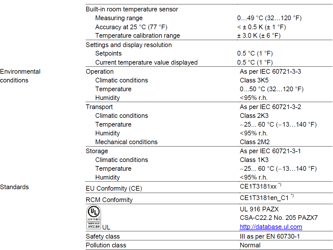
Technical data
Power supply
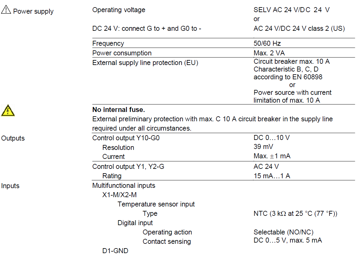
Connection terminals
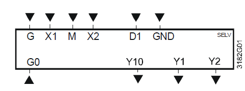
- G, G0: Operating voltage AC 24 V
- Y10/G0: Control output for DC 0…10 V actuator
- Y1/G, Y2/G: Control output for On/Off, PWM or 3-position actuators
- X1, X2: Multifunctional input for temperature sensor (e.g.QAH11.1) or potential-free switch
Factory setting
- X1: external room temperature sensor
- X2: sensor or switch for automatic heating/ cooling changeover
- M: Measuring neutral for sensor and switch
- D1, GND: Multifunctional input for the potential-free switch. Factory setting: Operating mode switchover contact
Connection diagrams
Application: Single-duct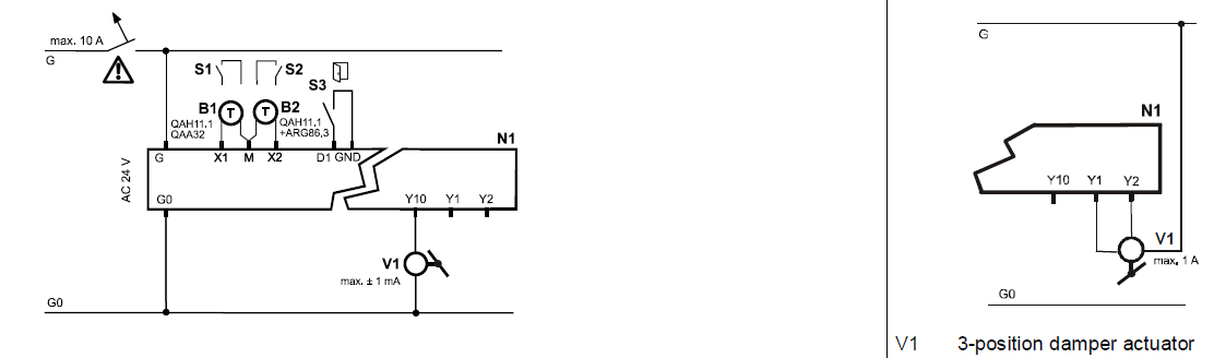
- V1: DC 0…10 V damper actuator
- N1: Room thermostat RDG400
- S1..S3: Switch (keycard, window contact, etc.)
- B1, B2: The temperature sensor (return air temperature, external room temperature, changeover sensor, etc.)
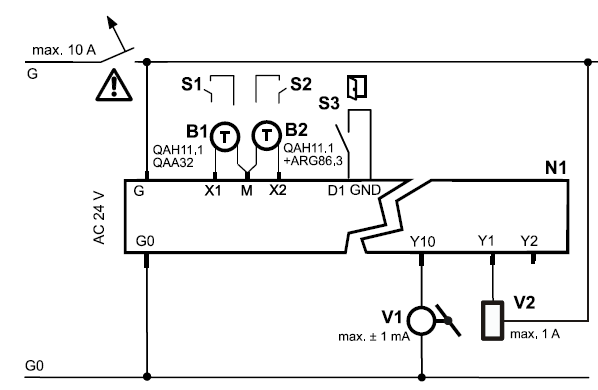
Application: Single-duct with electric heater, radiator or heating/cooling valve
- V1: DC 0…10 V damper actuator
- V2: On/Off or PWM electric heater, radiator or heating/cooling valve
- N1: Room thermostat RDG400
- S1..S3: Switch (keycard, window contact, etc.)
- B1, B2: The temperature sensor (return air temperature, external room temperature, changeover sensor, etc.)
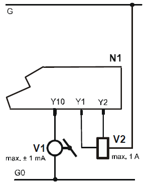
- V1: DC 0…10 V damper actuator
- V2: 3-position electric heater, radiator or heating/cooling valve
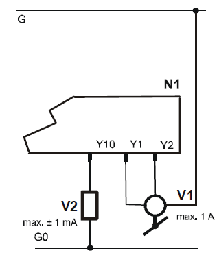
- V1: 3-position damper actuator
- V2: DC 0…10 V electric heater, radiator or heating/cooling valve
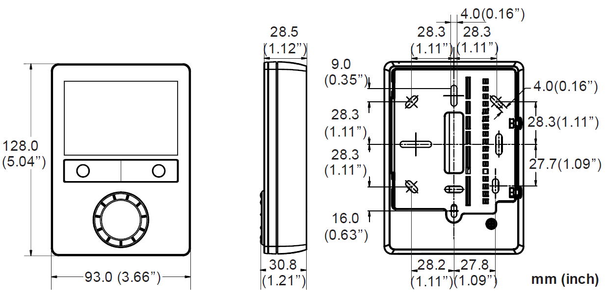
Dimensions
© Siemens Switzerland Ltd, 2009 – 2017
Technical specifications and availability are subject to change without notice.
Issued by
- Siemens Switzerland Ltd.
- Building Technologies Division International Headquarters Gubelstrasse 22
- CH-6300 Zug
- Tel. +41 58-724 24 24
- www.siemens.com/buildingtechnologies
REFERENCE:
DOWNLOAD MANUALS:
SIEMENS RDG400 Room Thermostat Product Specifications Guide
![]()
Leave a Reply