
Siemens RDF660MB Flush Mount Room Thermostat

Communications
- For 2-pipe, 2-pipe with electric heater and 4-pipe fan coil units
- AC 230 V operating voltage
- Large, backlit display
- On/off or 3-position control outputs
- Automatic or manual fan speed control
- ECM fan DC 0…10 V output
- Operating modes: Comfort, Economy and Protection
- Control depending on the room or the return air temperature
- Automatic or manual heating/cooling changeover
- Minimum and maximum limitation of room temperature setpoint
- 2 inputs for external or changeover sensor, keycard or window contact
- Commissioning and control parameters via local HMI or RS485 Modbus
- RS485 communicative interface in Modbus RTU slave mode
- User and parameter settings can be retained or restored with power loss to previous mode, Comfort mode or Protection mode
- Mounting on both round and square conduit boxes, 60 mm fixing centers
Use
Applications
Room temperature control (heating or cooling) in individual rooms and zones by means of:
- 2-pipe fan coil units
- 2-pipe fan coil units with electric heater
- 4-pipe fan coil units
The room thermostat controls:
- One ECM fan
- One or two on/off valve actuators
- One on/off valve actuator and one 1-stage electric heater
- One 3-position valve actuator
- One 1-stage compressor with electric heater
Used in systems with:
- Heating or cooling
- Automatic heating/cooling changeover
- Manual heating/cooling changeover
- Heating and cooling (e.g. 4-pipe system)
The room thermostat is delivered with a fixed set of applications. The relevant application is selected and activated during commissioning using one of the following tools:
- Local DIP switch and HMI
- Modbus commissioning tools
Functions
- Maintain room temperature via built-in temperature sensor or external room temperature/return air temperature sensor
- Changeover between heating and cooling mode (automatic changeover via local sensor/bus or manual changeover via buttons)
- Select application via DIP switches or commissioning tools
- Select operating mode via operating mode button on the thermostat
- ECM fan control (automatic or manual)
- Display current room temperature or setpoint in °C and/or °F
- Minimum and maximum limitation of room temperature setpoint
- Key lock (automatic, manual or via bus)
- B1 input freely selectable for (RDF660MB/MM only):
- External room temperature sensor or return air temperature sensor
- Automatic heating/cooling changeover sensor
- S1 input freely selectable for (RDF660MB/MM only):
- Window contact
- Presence detector
- Hotel keycard
- 2 multifunctional inputs (X1 and X2), freely selectable for (RDF660MB only):
- External room temperature sensor or return air temperature sensor (AI)
- Automatic heating/cooling changeover sensor (AI)
- Window contact (DI)
- Dew point sensor (DI)
- Electric heater enabled (DI)
- Fault input (DI)
- Monitor input (DI)
- Monitor input (AI)
- Automatic heating/cooling changeover sensor (DI)
- Presence detector (DI)
- Hotel keycard (DI)
- Advanced fan control function, e.g. fan kick, fan start, selectable fan operation (enable, disable or depending on heating or cooling mode)
- Purge function together with 2-port valve in a 2-pipe changeover system
- Reminder to clean filters
- Floor heating temperature limit
- Reload factory settings for commissioning and control parameters
- User and parameter settings can be retained with power loss and operating mode can be returned to previous operating mode, Comfort mode or Protection mode (depends on P27)
- RS 485 Modbus (terminals +, – and REF) for communication with Modbus compatible devices
- Display on a secondary line: room temperature, outdoor temperature or time of day via Modbus
- Mounting on both round and square conduit boxes, 60 mm fixing centers
Type summary
| Product no. | Stock no. | Operating voltage | Control outputs | Fan types | Backlit LCD | Input | Suitable conduit box | Color | |||
| On/Off | 3-pos | DC 0…10 V | 3-speed | DC 0…10 V | |||||||
| RDF660MB/ MM | S55770- T433 | AC 230 V | ✓ | ✓ | – | – | ✓ | ✓ | Basic B1, S1 | Square or round | White |
| RDF660MB | S55770- T439 | AC 230 V | ✓ | ✓ | – | – | ✓ | ✓ | Basic X1, X2 | Square or round | White |
Ordering
When ordering, specify both product number/stock number and name: e.g. RDF660MB/MM / S55770-T433 Modbus room thermostat Order valve actuators and accessories separately
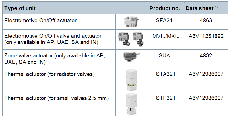
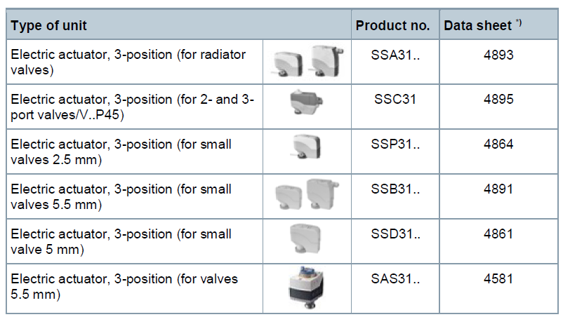
Accessories
Equipment combinations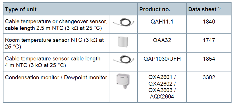
On/Off actuators
.3-position actuators
Mechanical design
The thermostats consist of 2 parts:
- Front panel with electronics, operating elements and built-in room temperature sensor.
- Mounting base with power electronics.
- The rear of the mounting base contains the screw terminals.
- The base fits on a square conduit box with 60 mm fixing centers.
- Slide the front panel in the mounting base and snap on.
Operation and settings
- Operating mode selector
- Change fan operation
- Adjust setpoints and control parameters

Display
- Operating mode
 Protection
 Comfort
 Economy
- Displays room temperature, setpoints and control parameters
 Symbol indicates current room temperature
- Fan mode
 Auto fan active
 Fan speed: low, medium, high
- Indicates fault or reminder
- Heating/cooling mode
 Cooling
 Heating
 Electrical heater active (RDF660MB only)
 Condensation in the room (dew point sensor active)
- Additional user information, like room temperature, outdoor temperature (
 ), or time from Modbus (selectable via parameters)
  Key lock active
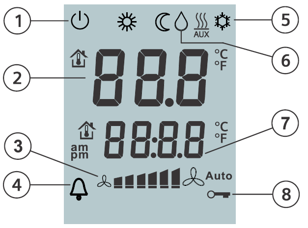
Product Documentation
| Title | Document ID |
| Operating instructions | A6V12060783 |
| Basic documentation | A6V12114068 |
| CE declarations | A5W00156993A |
| RCM | A5W00156996A |
| Environmental product declaration | A5W00139322A |
Engineering
- Device address: The device address is assigned to “1” (factory setting). If necessary, the engineer/installer can change the address value using the parameter.
- Baud rate: The Baud rate is selectable. Four options, 9600 bps, 19200 bps 38400 bps, and 57600 bps, are available for the Modbus network (19200 bps is the default).
- Parity: Parity can be set to none, odd or even (even is default).
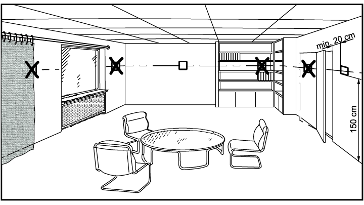
Mounting and installation
Mounting
- Mount the room thermostat on a recessed square conduit box with 60 mm fixing centers.
- Do not mount on a wall in niches or bookshelves, behind curtains, above or near heat sources, or exposed to direct solar radiation.
- Mount about 1.5 m above the floor.
- Mount the room thermostat in a clean, dry indoor place without direct airflow from a heating / cooling device, and not exposed to dripping or splash water.
- In case of limited space in the conduit box, use mounting bracket ARG70.3 to increase the headroom by 10 mm.
Wiring
- See Mounting Instructions A6V12060783 enclosed with the thermostat.
- Comply with local regulations to wire, protect and earth the thermostat.
- The device has no internal fuse for supply lines to fan and actuators. To avoid the risk of fire and injury due to short circuits, the AC 230 V mains supply line must have a circuit breaker with a rated current of no more than 10 A.
- Properly size the cables to the thermostat, fan and valve actuators for AC 230 V mains voltage.
- Use only valve actuators rated for AC 230 V.
- Adapt the wiring cross-section for power supply (L, N), and 230 V outputs (Yx-N) to the preceding overload protection elements (max 10 A) under all circumstances. Comply with local regulations under all circumstances.
- Cables of SELV inputs S1 (X2)-M / B1 (X1)-M: use cables with min 230 V insulation, as the conduit box carries AC 230 V mains voltage.
- Inputs S1 (X2)-M / B1 (X1)-M: several switches (e.g. summer/winter switch) may be connected in parallel. Consider the overall maximum contact sensing current for switch rating.
- Selectable relay function: Follow the instructions in Basic documentation A6V12114068 to connect external equipment to the relay outputs.
- Isolate the cables of Modbus communication input A+, B-, and REF for 230 V.
- Disconnect the thermostat from the power supply before removing it from the mounting plate.
- The device does not support hot-plug
Operating mode
In Protection mode, press any button to activate the screen, then press the mode button to change to another operating mode.
Commissioning
Applications
- The room thermostat is delivered with a fixed set of applications. Select and activate the relevant application during commissioning using one of the following tools:
- Local DIP switch and HMI
- Modbus commissioning tools
- Set the DIP switches before snapping the front panel onto the mounting plate, if you want to select an application via DIP switches.
All DIP switches need to be set to “OFF” (“remote configuration”), if you want to select an application via commissioning tools
Display “NONE”:
If “NONE” is displayed on the LCD, the DIP switches are set to OFF-OFF-OFF for remote configuration, but the application has not yet been assigned to the device. The application can be set using commissioning tools via RS485 Modbus.
Control parameters
The thermostat’s control parameters can be set to ensure optimum performance of the entire system. The parameters can be adjusted via
- Local HMI
- Modbus commissioning tools
Control sequence
The control sequence may need to be set via parameter P01 depending on the application. The factory setting for the 2-pipe application is “Cooling only”; and “Heating and cooling” for the 4-pipe application.
Compressor-based application
When the thermostat is used with a compressor, adjust the minimum output On-time (P48) and Off-time (P49) for Y1/Y2 to avoid damaging the compressor or shortening its life due to frequent switching
Calibrate sensor
Recalibrate the temperature sensor if the room temperature displayed on the thermostat does not match the room temperature measured (after minimum 1 hour of operation). To do this, change P05.
Setpoint and range limitation
We recommend reviewing the setpoints and setpoint ranges (P08…P12) and changing them as needed to achieve maximum comfort and save energy
Disposal
This symbol or any other national label indicate that the product, its packaging, and, where applicable, any batteries may not be disposed of as domestic waste. Delete all personal data and dispose of the item(s) at separate collection and recycling facilities in accordance with local and national legislation. For additional details, refer to www.siemens.com/bt/disposal.
Open Source Software (OSS)
All open source software components used within the product (including their copyright holders and the license conditions) can be found from the website https://www.siemens.com/download?A6V11893104.
Warranty
Technical data on specific applications are valid only together with Siemens products listed under “Equipment combinations”. Siemens rejects any and all warranties in the event that third-party products are used.
Technical data
| Power supply | |
| Operating voltage | AC 230 V +10/-15 % |
| Frequency | 50/60 Hz |
| Power consumption | 9 VA |
| ●No internal fuse! External preliminary protection with max. C 10 A circuit breaker is required in all cases. |
|
| Outputs | |
| DC fan control DC 0…10 V; Y50 | SELV DC 0…10 V, max. 5 mA |
| Control output
Y1-N / Y2-N (N.O.) Rating |
AC 230 V Max. 5(2) A |
| Multifunctional inputs | |
| S1 (X2)-M/B1 (X1)-M | |
| Temperature sensor input | |
| Type | NTC (3 kΩ at 25 °C) |
| Temperature range | 0…49 °C |
| Cable length | Max. 80 m |
| Digital input | |
| Operating action | Selectable (NO/NC) |
| Contact sensing | SELV DC 0…3.3 V, max. 1 mA |
| Parallel connection of several thermostats for one switch | Max. 20 thermostats per switch |
| Insulation against mains voltage (SELV) | III (4 kV), reinforced insulation |
| Modbus | |
| Interface type | RS485 Modbus RTU
Wire (ref.): 16 AWG, 1 pair, shielded serial line with 1.5 mm2 and length < 1200 m |
| Bus Current | Max. 50 mA |
| Bus topology: See Modbus manual (Modbus over serial line specification and implementation guide from http://www.modbus.org) | |
| Operational data | |
| Switching differential, adjustable | |
| Heating (P30) | 2 K (0.5…6 K) |
| Cooling (P31) | 1 K (0.5…6 K) |
| Setpoint setting and setpoint range | |
| Comfort (P08) | 21 °C (5…40 °C) |
| Economy (P11-P12) | 15 °C/30 °C (OFF, 5…40 °C) |
| Protection (P65-P66) | 8 °C/OFF (OFF, 5…40 °C) |
| Multifunctional input B1 (RDF660MB/MM only) | Selectable (0, 1, 2, 9) |
| Input default value (P38) | 9: H/C changeover (DI) |
| Multifunctional input S1 (RDF660MB/MM only) | Selectable (0, 3, 10, 11) |
| Input default value (P40) | 3: Window contact (DI) |
| Multifunctional inputs X1/X2 (RDF660MB only) | Selectable (0…11) |
| Input X1 | 3 (P38) Window contact (DI) |
| Input X2 | 1 (P40) External temperature sensor |
| Built-in room temperature sensor | |
| Measuring range | 0…49 °C |
| Accuracy at 25 °C | < ±0.5 K |
| Temperature calibration range | ±5 K |
| Settings and display resolution | |
| Setpoint | 0.5 °C |
| Current temperature value displayed | 0.5 °C |
| Environmental conditions | |
| Storage | IEC 60721-3-1 |
| Climatic conditions | Class 1K3 |
| Transport | IEC 60721-3-2 |
| Climatic conditions | Class 2K3 |
| Operation | IEC 60721-3-3 |
| Climatic conditions | Class 3K5 1) |
| Standards and directives | |
| EU conformity (CE) | A5W00156993A* |
| RCM conformity | A5W00156996A* |
| Safety class | II as per EN 60730-1 |
| Pollution class | Class 2 |
| Degree of protection of housing | IP30 as per EN 60529 |
| Housing flammability class according to UL94 | V-0 |
| Environmental compatibility | The product environmental declaration (A5W00139322A *) contains data on environmentally compatible product design and assessments (RoHS compliance, materials composition, packaging, environmental benefit, disposal). |
| General | |
| Connection terminals | Solid wires or prepared stranded wires
1 x 0.4…1.5 mm2 |
| Housing front color | RAL 9003 white |
| Weight without/with packaging | 148 g/241 g |
Diagrams
Connection terminals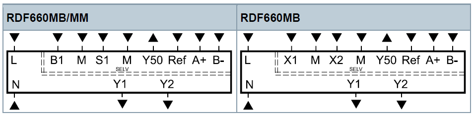
- L, N Operating voltage AC 230 V
- Y50 DC 0…10 V fan output
- M Reference for DC fan
- Y1, Y2 Control output “Valve” AC 230 V (N.O., for normally closed valves), output for compressor or output for electric heater
- B1, S1 (RDF660MB/MM only) Multifunctional input for temperature sensor (e.g. QAH11.1) or potential free switch
- Factory setting:
- B1 = H/C changeover (DI)
- S1 = Window contact
- X1, X2 (RDF660MB only)
- Multifunctional input for temperature sensor (e.g. QAH11.1) or potential free switch
- Factory setting:
- X1 = Window contact
- X2 = External temperature sensor
- M Measuring neutral for sensor and switch
- REF RS485 signal / common ground (differential common)
- A + RS485 Modbus connection
- B – RS485 Modbus connection
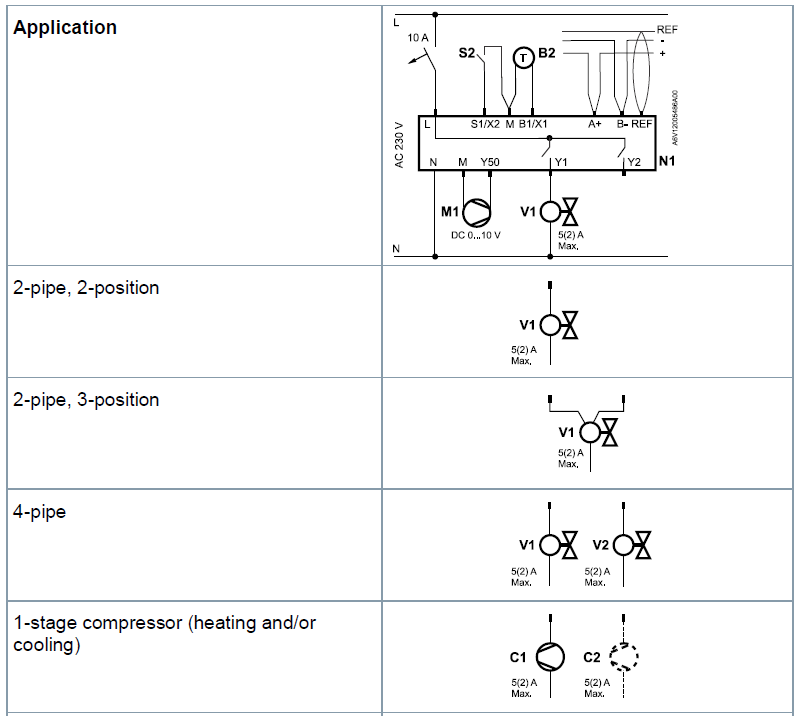
Connection diagrams
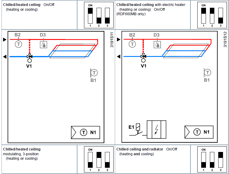
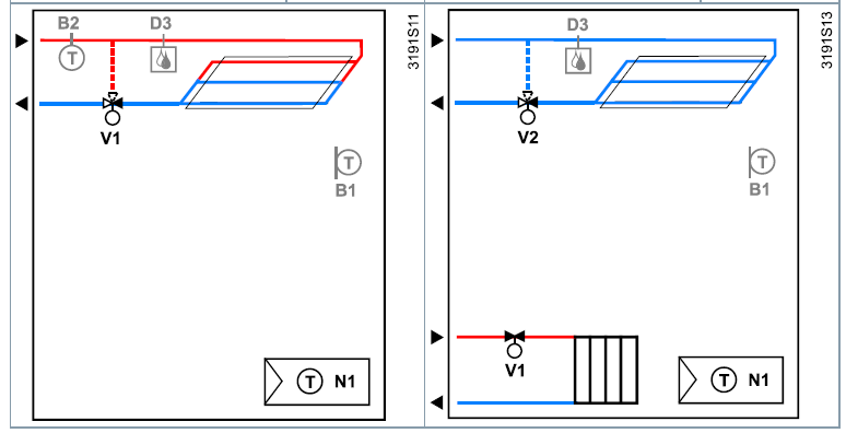
- N1 Room thermostat RDF660MB/MM, RDF660MB
- C1, C2 1-stage compressor
- V1 Valve actuator, 2- or 3-position V1, V2 Valve actuator, 2-position
- S2 Switch (keycard, window contact, presence detector, etc.)
- B2 Temperature sensor (return air temperature, external room temperature, changeover sensor, etc.)
- + RS485 Modbus connection – RS485 Modbus connection
- REF RS485 signal/common ground (differential common)
- M1 DC 0…10 V fan E1 Electric heater (RDF660MB only
Application examples
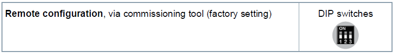
The thermostats support the following applications, that can be configured using the DIP switches inside the front panel of the unit or a Modbus commissioning tool.
Remote configuration
- All DIP switches need to be set to OFF (factory setting) to select an application via commissioning tool.
- Remote configuration, via commissioning tool (factory setting)
Applications for fan coil systems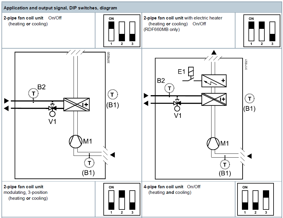
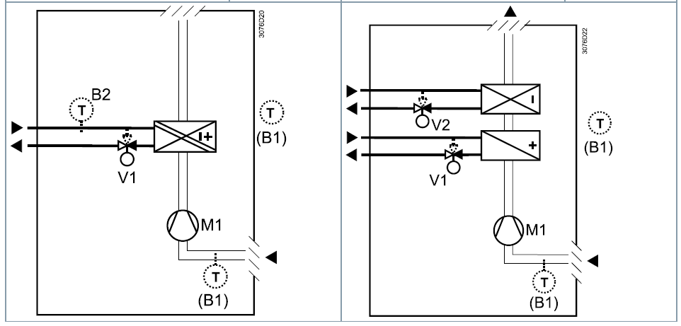
Application and output signal, DIP switches, diagram
Application for heat pump systems
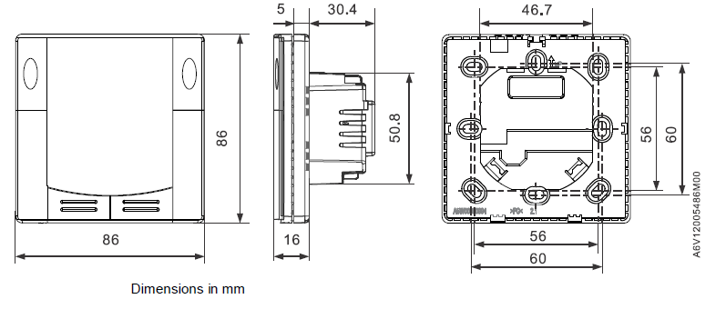
Dimensions
Issued by
- Siemens Switzerland Ltd.
- Building Technologies Division
- International Headquarters
- Theilerstrasse 1a
- CH-6300 Zug
- Tel. +41 58 724 2424
- www.siemens.com/buildingtechnologies
REFERENCE:
DOWNLOAD MANUALS:
Siemens RDF660MB Flush Mount Room Thermostat Product Specifications Guide
Other manuals:
Siemens RDF660MB Flush Mount Room Thermostat Operating Instruction
Siemens RDF660MB Flush Mount Room Thermostat Product Specifications Guide
Leave a Reply