
SIEMENS RDF310.2/MM Flush-mounted Room Thermostat

Flush-mounted Room Thermostat
- for 2-pipe fan coil units
SPECIFICATION
- Output for on/off valve or 3-wire on/off valve actuator
- 3-speed fan control: Automatic or manual
- Manual heating/cooling changeover or continuous Cooling only / Heating only
- Operating modes: Comfort, Protection
- Adjustable commissioning and control parameters
- Optional display of room temperature or setpoint
- Minimum and maximum setpoint limitation
- Display temperature in increments of 0.5 °C
- Operating voltage AC 230 V
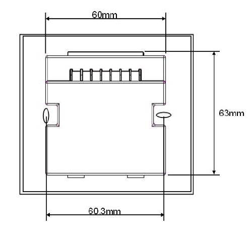
- Mounting on recessed square conduit box, fixing centres 60.3 mm
- User and parameter settings can be retained or restored with power loss
Use
For controlling the room temperature in individual rooms and zones that are
- heated or cooled with 2-pipe fan coil units
The thermostat controls
- a 3-speed fan
- an on/off valve actuator in a 2-pipe system
Suitable for use in systems with
- continuous heating or cooling mode
- manual heating/cooling changeover
Functions
- Manual changeover between heating and cooling mode
- Maintenance of room temperature with integrated internal temperature sensor
- Selection of operating mode with the operating mode button on the thermostat
- 3-speed fan control (automatic or manual)
- Output for 2-position (on/off) valve or 3-wire (on/off) valve actuator
Applications

- V1 Heating/cooling valve actuator
- M1 3-speed fan
- N1 Thermostat
Operation
Temperature control
- The thermostat acquires the room temperature via its built-in sensor and maintains the setpoint by delivering 2-position valve control commands.
- The switching differential is 1 K in heating mode and 1 K in cooling mode (adjustable via parameters P08 and P09).
Display
- The display shows the acquired room temperature or the setpoint of the current operating mode. This can be selected via parameter P18. The factory setting is a display of the current room temperature.
- The heating symbol
 or the cooling symbol
  displays to indicate the output status of the relays connected to the fan coil. This means that the symbol does not display when the thermostat operates in the neutral zone. If the thermostat is under manual heating or cooling changeover, the heating symbol or the cooling symbol displays permanently to indicate the control sequence. i.e. heating or cooling. This means that the symbol displays when the thermostat operates in the neutral zone.
 - If required, room temperature and setpoint can also be displayed in °F in place of °C by changing parameter P17
Operating modes
The following operating modes are available
- Comfort Mode

- In Comfort mode, the thermostat maintains the setpoint, which can be adjusted via the + and – buttons. The fan can be set to automatic or manual fan speed: Low, medium or high.
Tip!
The setpoint setting range can be limited to a minimum (P05) and maximum (P06). This helps prevent the waste of energy, and saving costs.
- In Comfort mode, the thermostat maintains the setpoint, which can be adjusted via the + and – buttons. The fan can be set to automatic or manual fan speed: Low, medium or high.
- Protection Mode

- When the thermostat is in Protection mode , the relevant setpoints of heating or cooling are maintained. These setpoints can be adjusted via control parameters P03 and P04. Factory setting of both setpoints is OFF, indicating the thermostat is not activated when in Protection mode
- When the thermostat is in Protection mode
- Avoiding damage due to moisture
- To avoid damage due to moisture in very warm and humid climatic zones resulting from lack of air circulation in Comfort mode, the fan can be kept running all the time (e.g. in apartments or shops during unoccupied periods), when setting parameter P21 “ON in dead zone”. In this case, the fan keeps running at minimum fan speed 1 in the neutral zone.
Control sequences
Water-based fan coil application
Used in conjunction with a valve, either for heating/cooling with changeover, or heating only, cooling only
ON
The valve receives the OPEN command via control output Y11 when
- the acquired room temperature lies by half the switching differential below the setpoint (heating mode) or above the setpoint (cooling mode), and
- control output Y11 was not energized for more than the “Minimum output off time” (factory setting 1 minute)
OFF
The valve receives the CLOSE command via control output Y11 when
- the acquired room temperature lies by half the switching differential above the setpoint (heating mode) or below the setpoint (cooling mode), and
- control output Y11 was energized for more than the “Minimum output on time”; (factory setting 1 minute)
Note:
Control output Y12 delivers a control command which is inverted to the control command at output Y11 and which can be used for normally open valves
Heating/cooling mode
- When you press the heating/cooling changeover button
 , the thermostat changes from heating to cooling, or vice versa.
 - If the thermostat is set to ”Cooling only” or ”Heating only” via P22, the manual changeover function on the button is not available (the factory setting of parameter P22 is ”manual changeover”). Instead, “NOP” flashes on the display, indicating continuous cooling or heating is set respectively
Minimum output on/off time Y11 and Y12
The minimum output on/off time of Y11 and Y12 is fixed at 1 minute. It means that any readjustment of the setpoint or of Heating/Cooling Mode changeover lasts for 1 minute before Y11 and Y12 react
Fan operation
- The fan operates either in automatic mode or at the selected speed when using manual mode. In automatic mode, the fan speed depends on the setpoint and the current room temperature. When the room temperature reaches the setpoint, the control valve is closed and the fan either remains in fan speed 1 or switches off (parameter P21, factory setting: fan speed 1 in dead zone).
- In “Temperature-dependent” fan control the fan switches off (please see diagram below). The individual switching differentials of the fan speed 1 (Q1 only) can be adjusted via control parameters P08 – P09. The individual switching differentials of the fan speed 2 and 3 (Q2 and Q3) are fixed at 1K.

Ventilation always on
If desired, fan control can be set to ”Temperature-independent”, which means that ventilation is always on, even within the dead zone, using at least fan speed 1. This can be selected individually for Comfort mode via parameter P21; also refer to “Avoiding damage due to moisture” on page 3).
Dwelling time
In automatic mode, a dwelling time of 2 minutes (factory setting) is active. The fan maintains that speed for at least 2 minutes before it switches to the next speed. This dwelling time can be adjusted from 1…5 minutes via parameter P14.
Fan start
Whenever the fan starts from a standstill, it starts with speed 3 for 1 second in order to guarantee a safe fan motor starts (to overcome inertia and friction).
Error handling
The temperature out of range
When the room temperature is out of the measuring range, which means above 49 °C or below 0 °C, the display shows the limiting temperature in flashing figures, e.g. “0 °C” or “49 °C”.
If the current setpoint is not OFF (see parameter P03) and the thermostat is in heating mode, when the temperature is below 0 °C, output Y11 is energized. In all other cases, output Y11 is de-energized until the temperature returns to the measuring range, and then the thermostat resumes Comfort mode.
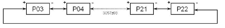
Control parameters
To optimize the control performance, you can use local HMI to adjust a number of control parameters. Proceed as follows to change the control parameter
Parameter settings
- Set the thermostat to Protection mode.
- Press and hold the + and – buttons simultaneously for 3 seconds. Release them and, within 2 seconds, press and hold the + button again for 3 seconds. Then, P03 displays.
- Select the required parameter by pressing the + and – buttons
- Press the + and – buttons simultaneously. Te current value of the selected parameter displays on the screen. Press the + or – button to change the value.
- You can either press the + and – buttons simultaneously to confirm the change or wait for 5 seconds to have the change saved automatically.
- Repeat steps 3 through 5 to change more parameters.
- 10 seconds after the last display or setting, all changes are saved and the thermostat returns to Protection mode
Parameter reset
Reload the factory setting of the control parameters as follows:
- Set the thermostat to Protection mode .
- Press the + and – buttons simultaneously for 3 seconds. Release them and, within 2 seconds, press the button twice.
Then 888 displays during the reloading process.
Control parameters
| Para- meter | Meaning | Setting range | Factory setting |
| P03 | Setpoint of heating in Protection Mode (WheatStb) | OFF, 5 °C…WcoolStb | 8 °C |
| P04 | Setpoint of cooling in Protection Mode (WcoolStb) | OFF, WheatStb …40 °C | OFF |
| P05 | Minimum setpoint limitation in Comfort Mode (WminNorm) | 5 °C…WmaxNorm | 5 °C |
| P06 | Maximum setpoint limitation in Comfort Mode (WmaxNormf) | WminNorm…40 °C | 35 °C |
| P07 | Sensor calibration | -3…3 K | 0 K |
| P08 | Switching differential heating mode SDH | 0.5…4 K | 1 K |
| P09 | Switching differential cooling mode SDC | 0.5…4 K | 1 K |
| P14 | Dwelling time of auto fan speeds | 1…5 min | 2 min |
| P17 | Selection of °C or °F | °C or °F | °C |
| P18 | Display of temperature or setpoint | OFF: Setpoint
ON: Room (or return air) temperature |
ON |
| P21 | Fan control in Comfort mode | OFF in dead zone ON in dead zone | ON |
|
P22 |
Heating/cooling mode |
0: Heating only
1: Cooling only 3: Manual H/C changeover |
3: Manual |
Equipment combinations
ON/OFF actuators
| Type of unit | Product no. | Data sheet |
Electromotoric ON/OFF actuator  |
SFA21… | 4863 |
| Electromotoric ON/OFF valve and actuator (only available in AP, UAE,
SA and IN)
|
MVI…/MXI… |
A6V11251892 |
Zone valve actuators (only available in AP, UAE, SA and IN) |
SUA… | 4832 |
Thermal actuator (for radiator valve)  |
STA23… | 4884 |
| Thermal actuator
(for small valves 2.5 mm) |
STP23… | 4884 |

Ordering
When ordering, please indicate the product name, product number and SSN number: (e.g. room thermostat, RDF310.2/MM, S55770-T187)
Valve actuators should be ordered separately
Mechanical design
The thermostat consists of two parts:
- Front panel which accommodates the electronics, the operating elements and the built-in room temperature sensor
- Mounting base with the power electronics
The mounting base carries on the rear side the screw terminals. It fits on a square conduit box with fixing centres 60.3mm. The front panel engages in the mounting base and snaps on.
Setting and operating elements
Legend
- Display of the room temperature, setpoints and control parameters
 The symbol used when displaying the current room temperature
- Protection mode / fan mode status
- Protection mode
- AUTO Auto fan active
 Fan speed low, medium, high
- output is energized (auto mode) / manual cooling mode (manual mode)
- output is energized (auto mode) / manual heating mode (manual mode)
- Comfort mode
- Buttons for adjusting the setpoints and control parameters
- Button for changing fan operation and Protection mode (
 )
) - Manual heating/cooling changeover
Mounting and installation
The thermostat can be mounted on a recessed square conduit box with fixing centres of 60.3 mm. The mounting location on a wall should not be in niches or bookshelves, not behind curtains, above or near heat sources and wind outlet or inlet, and not exposed to direct solar radiation. Mounting height is about 1.5 m above the floor
Wiring
Please also refer to the Mounting Instructions M3066… enclosed with the thermostat.
Wiring, protection and earthing must be installed in compliance with local regulations
Warning!
No internal line protection for supply lines to external consumers (Q1, Q2, Q3, Y11, Y12)
Risk of fire and injury due to short-circuits!
- Adapt the line diameters as per local regulations to the rated value of the installed overcurrent protection device.
- The AC 230 V mains supply line must have an external circuit breaker with a rated current of no more than 10 A.
- Only valves rated for AC 230 V may be used.
- Disconnect from supply before opening the cover
Commissioning
After applying power, the thermostat makes a reset during which all LCD segments flash, indicating that the reset has been correctly made. This takes about 3 seconds. Then, the thermostat is ready for commissioning by qualified HVAC staff. The control parameters of the thermostat can be set to ensure optimum performance of the entire system (please also refer to “Parameter settings”).
Heating/cooling mode
Set the heating/cooling mode via parameter P22 depending on the application. Factory setting is “Manual heat/cool changeover”. Set P22 accordingly in ”Cooling only” or “Heating only” mode
Calibrating the sensor
When the room temperature displays on the thermostat does not match the room temperature effectively measured, you can recalibrate the temperature sensor via parameter P07
Setpoint and range limitation
For comfort and energy saving reasons, it is suggested to review the setpoints and setpoint ranges (parameters P03…P06), if necessary, to change them accordingly.
Disposal
The device is considered electrical and electronic equipment for disposal in terms of the applicable European Directive and may not be disposed of as domestic garbage.
- Dispose of the device through channels provided for this purpose.
- Comply with all local and currently applicable laws and regulations
Technical data


Connection terminals

- L, N Operating voltage AC 230 V
- Q1 Control output “Fan speed 1 AC 230 V
- Q2 Control output “Fan speed 2 AC 230 V
- Q3 Control output “Fan speed 3 AC 230 V
- Y11 Control output “Valve” AC 230 V (N.O.)
- Y12 Control output “Valve” AC 230 V (N.C.)
Connection diagrams

- N1 RDF310.2/MM
- V1 On/off valve AC 230 V
- M1 3-speed fan

- N1 RDF310.2/MM
- V2 Electromotoric actuator, e.g. SUA21/1
- M1 3-speed fan
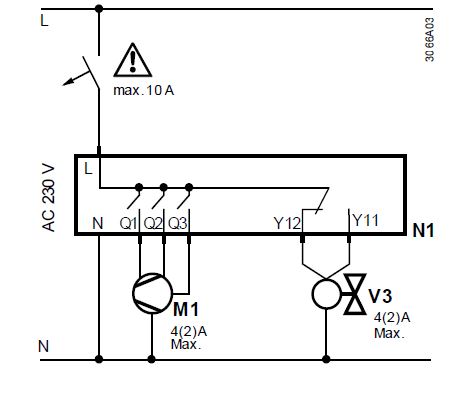
- N1 RDF310.2/MM
- V3 3-wire on/off (SPDT) zone valve
- M1 3-speed fan
Dimensions


© Siemens Switzerland Ltd, 2010 – 2019
Technical specifications and availability are subject to change without notice.
Issued by Siemens Switzerland Ltd Smart Infrastructure Global Headquarters Theilerstrasse 1a
CH-6300 Zug
Tel. +41 58 724 2424
www.swww.siemens.iemens.ccom/buildinom/buildingtechngtechnologologiieses
Siemens Smart Infrastructure
Flush-mounted Room Thermostat
REFERENCE:
DOWNLOAD MANUALS:
SIEMENS RDF310.2MM Flush-mounted Room Thermostat Product Specifications Guide
![]()
SIEMENS RDF310.2/MM Flush-mounted Room Thermostat Product Specifications Guide
Leave a Reply