
SIEMENS RDD810 Flush Mount Touch Screen Room Thermostat

For heating applications
- Large display with backlight
- 2P / PI / P control
- 2-position (ON/OFF) control with potential free output for heating
- 2 multifunctional inputs for the keycard, window contact, external temperature sensor, presence detection, and etc.
- Operating modes: Comfort, Economy and Protection
- Minimum and maximum limitation of room temperature setpoint
- Control depending on the room or external temperature sensor
- Adjustable commissioning and control parameters
- AC 230 V operating voltage
- RDD810: Mounting on round box, with min 60 mm diameter or recessed square 86 mm box with 60.3 mm fixing centers and min 40 mm depth
- RDD810/NF: Mounting on recessed square 86 mm box with 60.3 mm fixing centers and min 40 mm depth, requires additional mounting frame
Use
Room temperature control in a heating system:
Typical applications:
- Apartments
- Commercial buildings
- Schools
For the control of the following pieces of equipment:
- Thermal valves or zone valves
- Gas or oil boilers
- Pumps
- Floor Heating
Functions
- Room temperature control via built-in temperature sensor or external room temperature sensor
- Selection of operating mode via touchscreen
- Temporary Comfort mode extension
- Display of current room temperature or setpoint in °C and/or °F
- The minimum and maximum limitation of room temperature setpoint
- Key lock function: unlock, total lock and setpoint
- 2 multifunctional inputs, freely selectable for:
- External room temperature or return air temperature sensor
- Window contact
- Fault input
- Monitor input for temperature sensor or switch state
- Presence detector
- Floor heating temperature limitation
- Reload factory settings for commissioning and control parameters
- Wizard function for easy commissioning via HMI
The functional descriptions for the thermostat can be referred to the basic documentation P3174
Applications
The thermostat supports the heating applications:
- Hydronic floor heating controls
- Radiators
- Wall-hung boilers
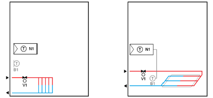
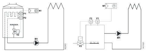
Application Examples
- Room thermostat to control the valve of the radiator application
- Room thermostat to control the valve for the floor heating application
- Room thermostat with direct control of a gas-fired wall-hung boiler
- Room thermostat with direct control of a gas-fired floor-standing boiler
- Room thermostat with direct control of a heat pump (pre-controlled by manual mixing valve)
- Room thermostat with direct control of hydronic floor heating system
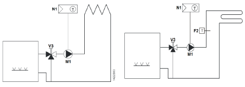
- F1 Thermal reset limit thermostat
- F2 Safety limit thermostat
- M1 Circulating pump
- N1 Room thermostat
- V1 2-port valve
- V2 Mixing 3-port valve with manual adjustment
- V3 Magnetic valve
Type summary
|
Product no. |
Stock no. |
Operating voltage | Control outputs |
Suitable for |
||
| 3-pos | ON/OFF | DC 0..10 V | ||||
| RDD810/NF 2) | S55770-T406 | AC 230 V | — | 2 1) | — | Square conduit box 2) |
| RDD810 3) | S55770-T443 | AC 230 V | — | 2 1) | — | Round or square conduit box |
- ON/OFF output with potential free input from AC 24…230 V
- Mounting frame (ARG800.1) is not included and must be ordered separately. See “Accessories”
- Additional mounting frame is not required.
Ordering
- When ordering, indicate product number, SSN and name.
For example: RDD810/NF (S55770-T406) room thermostat - A mounting frame must be ordered for RDD810… installation (See “Accessories”)
- Order valve actuators separately.
Equipment combinations
| Type of unit | Product no. | Data sheet | |
| Cable temperature sensor or changeover sensor
cable length 2.5 m NTC (3 kW at 25 °C) |
|
QAH11.1 d) |
1840 |
| Room temperature sensor NTC (3 kW at 25 °C) |  |
QAA32 | 1747 |
| Cable temperature sensor, cable length 4 m
NTC (3 kW at 25 °C) |
 |
QAP1030/UFH |
1854 |
| Electromotoric ON/OFF actuator |  |
SFA21… | 4863 |
| Electromotoric ON/OFF valve and actuator a) | 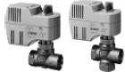 |
MVI…/MXI… | A6V11251892 |
| Zone valve actuators a) | 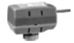 |
SUA… | 4832 |
|
Thermal actuator b) |
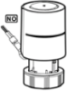 |
STP..21.. |
A6V12986007 |
|
Thermal actuator c) |
 |
STA..21.. |
A6V12986007 |
| Damper actuator | 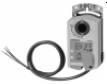 |
GDB.. | 4634 |
|
Damper actuator |
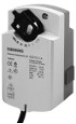 |
GSD.. |
4603 |
|
Damper actuator |
 |
GQD.. |
4604 |
| Rotary damper actuator |  |
GXD.. | 4622 |
- only available in AP, UAE, SA and IN
- for radiator valve
- for small valves 2.5 mm
- both QAH11.1 and QAP1030/UFH are for floor heating applications, such as temperature limitation controls. QAP1030/UFH has a special head and 4 m long that is more suitable for such application
Note:
Refer to data sheets of the actuators for the maximum number of parallel operation
Accessories
| Designation | Product no. / SSN | Data sheet | |
| Single mounting frame, Ivory White*) | 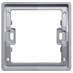 |
ARG800.1 / S55770-T370 |
— |
*) See the dimensions of mounting frame on page 18.
Mechanical design
The thermostats consist of the following parts:
- Front panel with electronics, operating elements and built-in room temperature sensor.
- Mounting base with power electronics.
- Mounting frame is an additional part to complete the installation for RDD810…
The rear of the mounting base contains the screw terminals. Slide the front panel in the mounting base and snap on
Operation and settings

Display
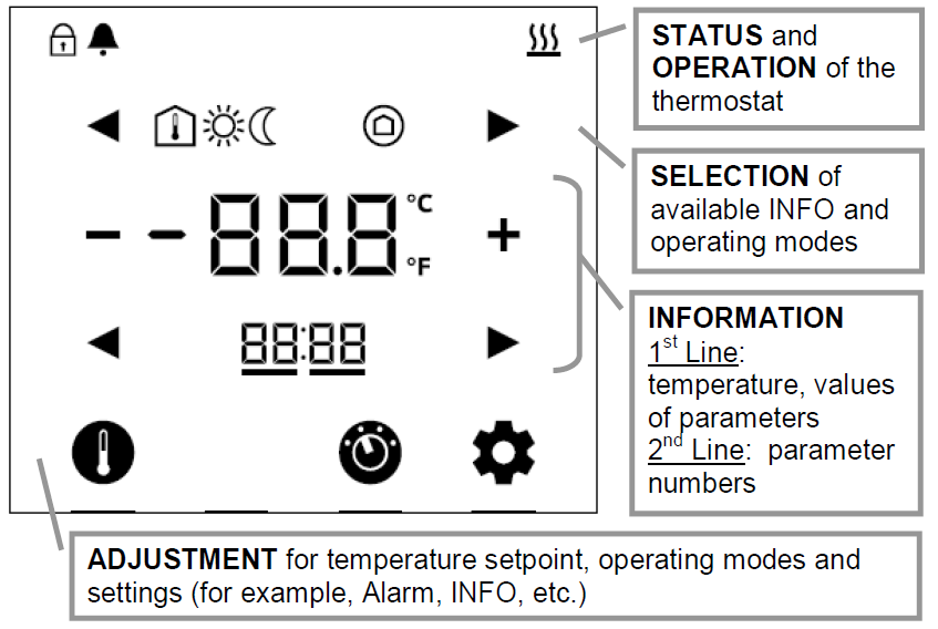
| Status symbols: | |||
| |
Key lock | |
Heating active |
| |
Alarm / Service reminder | ||
| Selection symbols: | |||
|
Indoor temperature |
|
Comfort mode |
|
| |
Protection mode |
|
Economy mode |
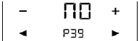
| Operational icons: | |
| + ̶ | Increment, decrement OR selection |
| Selection OR move to next items | |
| |
Temperature OR parameter values, and etc. |
| |
Parameter number OR password, and etc. |
| |
Setpoint mode (temperature only) |
| |
Operating mode |
| |
Setting mode |
Engineering notes
See the “Reference documentation”, page 14, for information on how to select and dimension connecting cables for supply voltage and field devices
Mounting and installation
Mount the room thermostat on a conduit box. Do not mount on a wall in niches or between bookshelves, behind curtains, above or near heat sources, or exposed to direct solar radiation. Mount about 1.5 m above the floor.
![]() Mounting / Dismounting
Mounting / Dismounting
- Do not apply excessive force on screws! The deformation of the mounting frame may lead to improper connections and operation of the unit.
- Mount the room thermostat on a clean, dry indoor place without direct airflow from a heating / cooling device, and not exposed to drips or water.
- Before removing the front cover, disconnect the power supply.
Wiring See the User Manual for the installation instructions enclosed with the thermostat.
 Comply with local regulations to wire, protect and earth the thermostat.
- The device has no internal fuse for supply lines to fan and actuators. To avoid risk of fire and injury due to short-circuits, the AC 230 V mains supply line must have a circuit breaker with a rated current of no more than 10 A.
- The wiring cross section used for power supply (L, N) and 230 V outputs (Qxx – N) must be adapted to the preceding overload protection elements (max 10 A) under all circumstances. Comply under all circumstances with local regulations.
- Properly size the cables to the thermostat and valve actuators for AC 230 V mains voltage.
- Cables of SELV inputs X1-M / X2-M: Use cables with min 230 V insulation, as the conduit box carries AC 230 V mains voltage.
- Inputs X1-M or X2-M of different units (e.g. window contact) may be connected in parallel with an external switch. Consider overall maximum contact sensing current for switch rating.
- No cables are provided with a metal shield.
- Disconnect from supply before opening the cover
Commissioning notes
Before power up
No DIP switch setting is required for RDD810… thermostats
Wizard function
After power up, the wizard function guides users to configure the basic parameters for normal operation according to the table below. Touch ![]() to advance / return to any parameter; Touch
to advance / return to any parameter; Touch ![]() to change value
to change value
| LCD display | Parameter | Range | Factory setting |
 |
User operating mode profile |
1: comfort > protection
2: comfort > economy > protection |
1 |
 |
Selection of
° C or °F |
0: °C
1: °F |
0 |
 |
Standard display |
0: Room temperature
1: Setpoint |
0 |
 |
Display info line (2nd line of LCD display) | 0: — (No display)
3: Time of day (12h) via bus 4: Time of day (24h) via bus |
0 |
|
Functionality of X1 |
0: — No function
1: Ext / Return Temp (AI) 3: Window open detect (DI) 6: Fault input (DI) 7: Monitor input (Digital) 8: Monitor input (Temp) 10: Presence detection (DI) |
3 |
 |
Functionality of X2 |
1 |
|
 |
Operating action of X1 |
Normal Open (NO) Normal Close (NC) |
Normal Open (NO) |
 |
Operating action of X2 | ||
| |
– |
End of wizard |
– |
If more details are required about parameters, refer to basic documentation P3174.
Reset
To reload factory setting for all parameters, set parameter P71 to ON. Restart the thermostat after reset, all LCD segments flash, indicating that the reset is correct. 3 seconds later, the thermostat is ready for commissioning by qualified HVAC staff
Applications
RDD810… thermostats are for heating applications. Configure or changing parameter settings during commissioning using one of the following tools: − Local HMI
Setting parameters using the local HMI
Service level parameters
| Parameter | Name | Factory setting | Range | Resolution |
| Service level | ||||
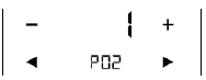
| P02 | User operating mode profile (mode button) | 1 = Comf – Protection | 1 = Comf – Protection
2 = Comf – Econ – Protection |
|
| P04 | Selection of °C or °F | 0 = °C (Degrees Celsius) | 0 = °C (Degrees Celsius)
1 = °F (Degrees Fahrenheit) |
|
| P05 | Sensor calibration (intern, extern) | 0 K | -5 K…+5 K | 0.5 K |
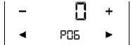
| P06 | Standard temperature display | 0 = Room Temperature | 0 = Room Temperature
1 = Setpoint |
|
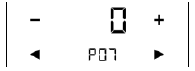
| P07 | Display info line
(2nd line of LCD) |
0 | 0 = — (No display)
1 = °C and °F |
|
| P08 | Comfort setpoint | 21 °C | 5…40 °C | 0.5 K |
| P09 | Minimum setpoint in Comfort mode | 5 °C | 5…40 °C | 0.5 K |
| P10 | Maximum setpoint in Comfort mode | 35 °C | 5…40 °C | 0.5 K |
| P11 | Economy heating setpoint | 15 °C | OFF, 5…30 °C | 0.5 K |
| P14 | Keylock function | 0 | 0 = Unlock
1 = Locked
2 = Setpoint |
|
| P16 | Buzzer function | ON = Enabled | ON = Enabled
OFF = Disabled |
Note: Parameter display depends on the selected application and function.
Expert-level parameters with diagnostics and test
| Parameter | Name | Factory setting | Range | Resolution |
| Expert level | ||||
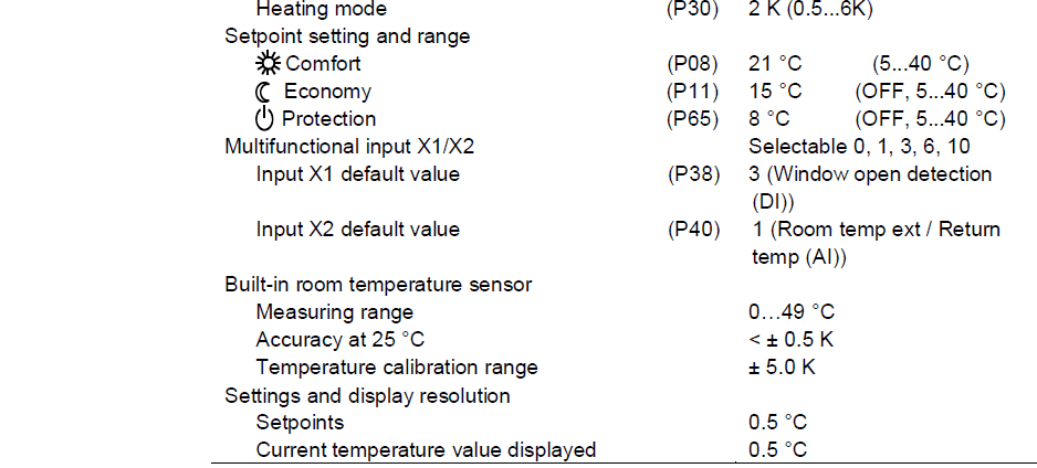
| P30 | P-band / Switching differential in heating mode | 2 K | 0.5…6 K | 0.5 K |
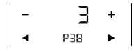
| P38 | Functionality of X1 | 3 = Window open detection (DI) | 0 = — (no function)
1 = Room temp ext / Return temp (AI) 3 = Window open detection (DI) 6 = Fault input (DI) 10 = Presence detection (DI) |
|
| P39 | Operating action of X1 if digital input | 0 = Normally open / Open | 0 = Normally open / Open 1 = Normally closed / Close |
|
| P40 | Functionality of X2 | 1 = Room temp ext / Return temp (AI) | 0 = — (no function) 1 = Room temp ext / Return temp (AI) 3 = Window open detection (DI) 6 = Fault input (DI) 10 = Presence detection (DI) |
|
| P41 | Operating action of X2 if digital input | 0 = Normally open / Open | 0 = Normally open / Open
1 = Normally closed / Close |
|
| P48 | Minimum output on time 2-position control output | 1 min. | 1…20 minutes | 1 min. |
| P49 | Minimum output off time 2-position control output | 1 min. | 1…20 minutes | 1 min. |
| P51 | Floor heat limit temperature | OFF | OFF, 10..50 °C | 1 K |
| P65 | Protection heating setpoint | 8 °C | OFF, 5 … WcoolPro;
WCoolPro = 40 °C max |
0.5 K |
| P69 | Temporary setpoint comfort (see also comfort basic setpoint) | OFF = Disabled | OFF = Disabled ON = Enable | |
| P71 | Reload factory setting | OFF = Disabled | OFF = Disable
ON = Reload factory setting Reload starts only after exits parameter mode. |
|
| P77 | Presence Detector Mode | 1: Standard Presence Mode | 1: Standard Presence Mode
2: Hotel Presence Mode |
| Parameter | Name | Factory setting | Range | Resolution |
| Diagnostics and test | ||||
| d011) | Application no | Diagnose | H | |
| d02 | X1 status | Diagnose
(display values according to the selected function of X1: DI, AI, HC changeover, etc) |
0 = Not activated (for DI) 1 = activated (DI)
0…49 °C = cur. temp. value (for AI) |
|
| d03 | X2 status | Diagnose
(display values according to the selected function of X1: DI, AI, HC changeover, etc) |
0 = Not activated (for DI) 1 = activated (DI)
0…49 °C = cur. temp. value (for AI) |
0.5 K |
| d07 | Host software version
Show Ux.xx |
d01 shows H meaning heating.
Control parameters
The thermostat’s control parameters can be set to ensure optimum performance of the entire system (refer to basic documentation P3174). The parameters can be adjusted using Local HMI For commissioning via local HMI, refer to user manual B3174… for setting the passwords.
Control sequence
Only heating sequence is available
Calibrate sensor
Recalibrate the temperature sensor if the room temperature displayed on the thermostat does not match the room temperature measured (after min. 1 hour of operation). To do this, change parameter P05
Setpoint and range limitation
We recommend to review heating setpoint and their range limitation via parameters P08…P11. If necessary, adjust them to achieve maximum comfort and save energy
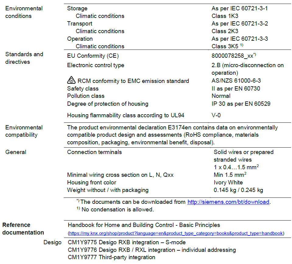
Disposal
The device is considered electrical and electronic equipment for disposal in terms of the applicable European Directive and may not be disposed of as domestic garbage.
![]()
- Dispose of the device through channels provided for this purpose.
- Comply with all local and currently applicable laws and regulations.
Technical data
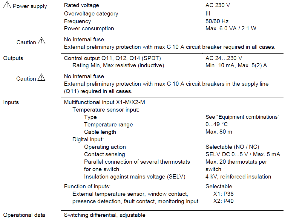
Connection terminals
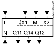
- L, N Operating voltage AC 230 V
- Q11, Q12 NC contact (for NO valves)
- Q11, Q14 NO contact (for NC valves)
- X1, X2 Multifunctional input for temperature sensor or potentialfree switch
Factory setting:- X1 = Window contact
- X2 = External sensor
(function can be selected via parameter P38 / P40)
- M Measuring neutral for sensor and switch
Connection diagrams
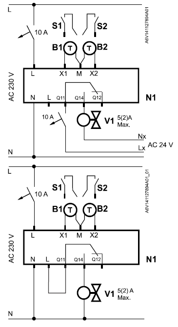
- N1 Room thermostat
- V1 Valve actuator
- Lx AC 24…230 V
- S1, S2 Switch (keycard, window contact, presence detector, etc.)
- B1, B2 Temperature sensor (return air temperature, external room temperature, changeover sensor, etc.)
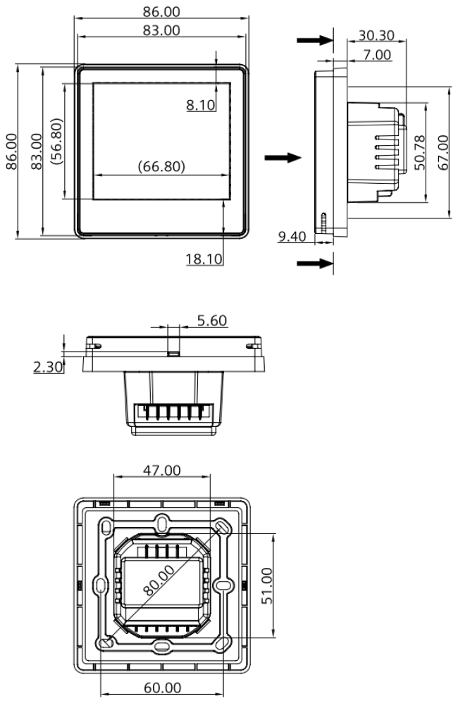
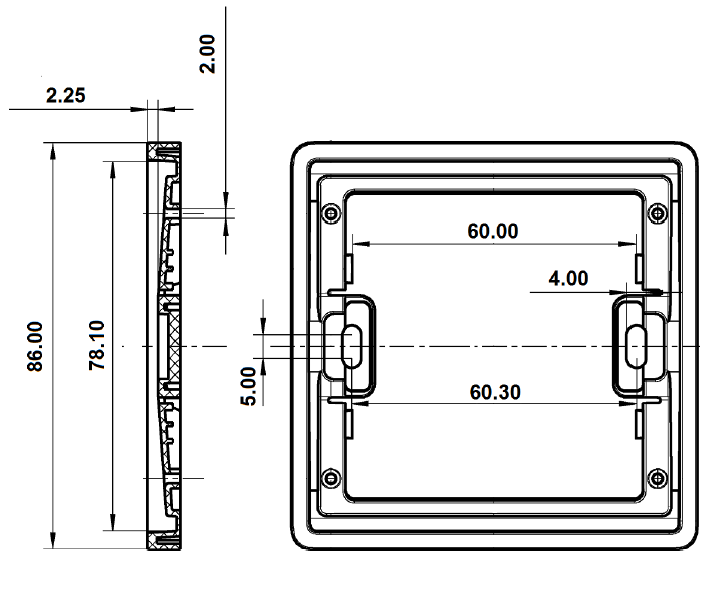
Dimensions mm
RDD810/NF for square conduit boxes only
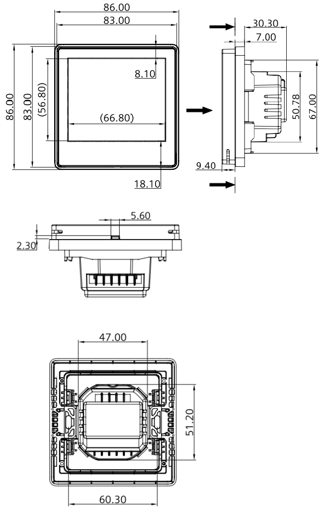
RDD810 for round conduit boxes
ARG800.1 single mounting frame for RDD810/NF
Issued by Siemens Switzerland Ltd Smart Infrastructure Global Headquarters Theilerstrasse 1a CH-6300 Zug Tel. +41 58 724 2424 www.siemens.com/buildingtechnologies
© Siemens Switzerland Ltd, 2019 Technical specifications and availability subject to change without notice.
REFERENCE:
DOWNLOAD MANUALS:
SIEMENS RDD810 Flush mount touch screen room thermostat Product Specifications Guide
![]()
SIEMENS RDD810 Flush Mount Touch Screen Room Thermostat Product Specifications Guide
Leave a Reply