
SIEMENS RDD510 F Heating or Cooling Room Thermostat

For heating or cooling only units
- LCD backlit display
- Keylock function
- Display either room temperature or setpoint
- Comfort and Protection(Off) operating modes
- Timer with delay Off function: preset or user selection from 1 to 23 hours
- Minimum and maximum setpoint limitation
- Return to previous operating mode or Protection(Off) upon power down
- Internal sensor calibration
- Adjustable commissioning and control parameters
- Fit into 86×86 square conduit boxes
- Three standard color variants are available: reference color codes are WHITE (RAL 9003), SILVER (Cool Grey 4C), GOLD (Gold 453C), BLACK (Pantone Black 7C)
- Customization is available
Use
To control the room temperature in individual rooms using:
Heating or cooling-only equipment (RDD510)
The thermostats control:
One on/off valve actuator
Functions
- Maintenance of room temperature via built-in temperature sensor
- Control sequence Heating or Cooling only selection (P01)
- Operating mode selection via button
- Display either room temperature value or setpoint value (P06)
- Internal sensor calibration (P05)
- Minimum and maximum setpoint limitation (P09&P10)
- Full or partial keylock (P14)
- Reload factory settings for commissioning and control parameters (P71)
- On/Off output for valve actuator
Advanced functions
- Timer with delay Off (P28)
- Operating mode settings upon power down (P27)
Mechanical design
The thermostat consists of two parts:
- One LCD display and five key buttons on the user interface.
- One mounting plate for fitting onto a square conduit box with 60.3 mm fixed meters.
Operating and setting elements

- Keylock activated
- Timer with delay Off mode
- Cooling mode selected
- Cooling mode selected
- Heating mode selected
- Operating mode selection: On, Off, timer with delay Off
- 3 key buttons to adjust setpoints and operating modes while 2 non-functional key buttons are required for parameter mode and other access
- Temperature setpoint adjustment
- Temperature value
- Room temperature
Type summary
Ordering
| Type | Stock Number | Designation |
| RDD510 | Upon request | Room thermostat (White) in single pack of 1 unit |
| RDD510/BP | S55770-T425 | Room thermostat (White) in bulk pack of 20 units |
| RDD510/BP.VS | S55770-T432 | Room thermostat (Silver) in bulk pack of 20 units |
| RDD510/BP.VB | Upon request | Room thermostat (Black) in bulk pack of 20 units |
| RDD510/BP.VG | Upon request | Room thermostat (Gold) in bulk pack of 20 units |
Delivery
Order valve actuators separately.
Equipment combinations
| Type of units | Product number | Data Sheet | |
| Electromotor ON/OFF valve and actuator (only available in AP, UAE, SA and IN) | 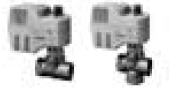 |
MVI…/MXI… | A6V11251892 |
| Electromotoric ON/OFF actuator |  |
SFA21… | N4863 |
| Thermal actuator (for radiator valve) AC 230 V, NO |  |
STA23… | N4884 |
| Thermal actuator (for radiator valves) AC 24 V, NO |  |
STA73… | N4884 |
| Thermal actuator AC 230 V (for small valves 2.5 mm) , NC |  |
STP23… | N4884 |
| Thermal actuator AC 24 V (for small valves 2.5 mm), NC |  |
STP73… | N4884 |
| Zone valve actuators (only available in AP, UAE, SA and IN) |  |
SUA… | N4832 |
| Damper actuator |  |
GDB… | N4634 |
| Damper actuator |  |
GSD… | N4603 |
| Damper actuator |  |
GQD… | N4604 |
| Rotary damper actuator |  |
GXD… | N4622 |
All documents can be downloaded from https://www.downloads.siemens.com/downloadcenter/.
Product Documentation
| Title | Document ID |
| Mounting and operating instructions | A6V11881111 |
| CE declarations | A6V101090515 |
| Environmental declarations | A5W00085405A |
All the documents can be downloaded from https://www.downloads.siemens.com/downloadcenter/.
Notes
Security
 |
CAUTION |
| National safety regulations
Failure to comply with national safety regulations may result in personal injury and property damage ● Observe any national provisions and comply with the appropriate safety regulations. |
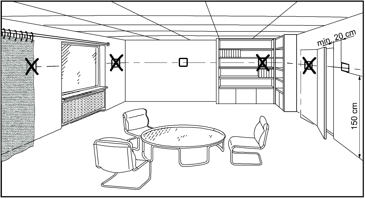
Mounting
Do not wall-mount in niches or bookshelves, behind curtains, above or near heat sources, wind outlets or inlets, and do not expose to direct solar radiation. Mount about 1.5 m above the floor.
|
WARNING |
| Wire, protect, and earth in compliance with local regulations.
Current loading is limited by a standard slow-blow 6.3 A fuse (replaceable). Risk of fire and injury due to short circuits! ● Adapt the line diameters as per local regulations to the rated value of the installed overcurrent protection device. ● The AC 230 V mains supply line must have an external circuit breaker with a rated current of no more than 10 A. ● Use only valve actuators rated for AC 230 V. ● Disconnect from supply before removing the unit from its mounting plate. ● Do not connect terminal Y12 to either L or N. ● Do not use terminal Y12 as AC 230 V power supply. |
Commissioning
After powering up, the thermostat resets and all LCD segments light up for about 3 seconds. Afterward, the room temperature is displayed (factory setting) and the unit is ready for commissioning by qualified HVAC staff.
The thermostat’s control parameters can be adjusted to ensure the optimum performance of the entire system (see “Parameter settings”).
Surge protection at power-up
When the thermostats are powered up, LCD display and key buttons work normally except all valve outputs, e.g., Y12, Y14.
The outputs of thermostats start up at random to protect the mains from overload. It may take up to two minutes before all outputs of thermostats work properly.
Sensor calibration
The thermostat has an internal sensor for accurate temperature display. If the temperature display is influenced by its installation location, calibrate the sensor via parameter P05 to adjust the readings.
Setpoint and range limitation
For comfort and energy saving reasons, we suggest to review the setpoints and setpoint ranges (parameters P09, P10, P65 and P66) and change them as needed.
Control sequences
On/Off control
On 2-pipe applications, the thermostat controls an On/Off valve in heating/cooling mode (P01 = 0, factory set).
Heating mode

- T[°C] Room temperature
- W Room temperature setpoint
- YH Control command “Valve” (heating)
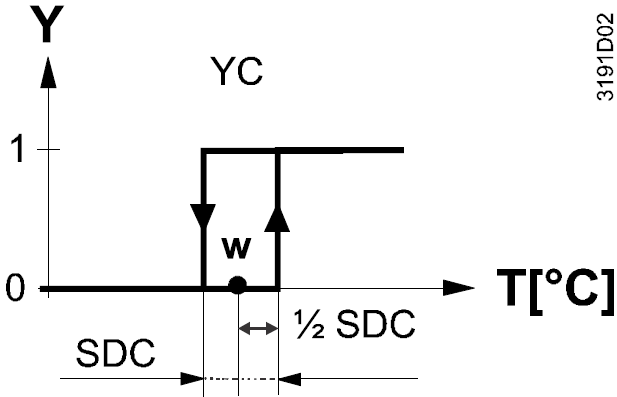
Cooling mode
- SDH Switching differential “Heating”
- SDC Switching differential “Cooling”
- YC Control command “Valve” (cooling)
On/Off control signal
The valve receives the On command via control output Y14 when:
- The acquired room temperature is below the setpoint (for heating mode) or above the setpoint (for cooling mode), and
- The control output was not energized for more than the “Minimum output off time” (factory setting 1 minute)
The valve receives the Off command when:
- The acquired room temperature is above the setpoint (for heating mode) or below the setpoint (for cooling mode), and
- The control output was energized for more than the “Minimum output on time”; (factory setting 1 minute)
Note:
- Control output Y12 delivers a control command which is inverted to the control command at output Y14 that can be used for normally open valves.
- Valve output can respond immediately and does not consider minimum On/Off time if users manually adjust the setpoint via local HMI.
Error handling
Temperature out of range
Factory setting of the heating/cooling setpoint in Protection mode is Off, i.e. overheating/frost protection is disabled.
In this case, when the room temperature is out of range, i.e. above 49 °C or below 0 °C, the temperature displays and flashes at and the thermostat continues to work.
Sensor error
When the internal sensor is not working properly, is displayed.
Control parameters
Parameter settings
To optimize control performance, use the local HMI to adjust a number of control parameters. All control parameter settings are retained after power down. Proceed as follows to change the control parameters:
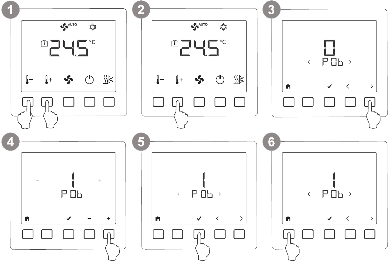
- Press and hold down the + and – buttons simultaneously for more than 3 seconds.
- Release the buttons, and within 2 seconds, press and hold down the + button for 3 seconds. P01 is displayed.
- Press < or > to access the desired parameter and press the √ button. The current value of the selected parameter is displayed.
- Press the + or – button to change the value.
- Press the √ button to confirm the change, and repeat steps 3 to 5 to change more parameters.
- Press
 to exit the parameter setting mode
Reload factory setting
- Select parameter P71 and set it to On.
- The factory settings of the control parameters are reloaded. – “- – -” is displayed on the screen while reloading.
Control parameters
| Parameter | Description | Factory setting | Setting range |
| P01 | Control sequence | RDD510 = 0 | 0:= Heating only
1:= Cooling only |
| P05 | Sensor calibration | 0 K | -5…+5 K |
| P06 | Standard temperature display | 0 | 0:= Room temperature
1:= Setpoint |
| P09 | Minimum setpoint in Comfort mode | 5 ℃ | 5…40 ℃ |
| P10 | Maximum setpoint in Comfort mode | 35 ℃ | 5…40 ℃ |
| P14 | Keylock function | 0 | 0:= No lock
1:= Full lock 2:= Partial lock |
| P27 | Operating mode settings upon power down | 0 | 0:= Return to previous operating mode or user settings
1:= Protection mode 2: = Comfort mode |
| P28 | Timer with delay Off | 0 | 0:= Users to set on-time duration 1 to 23:= Preset with a fixed on-
time in hours |
| P30 | Switching differential in heating mode | 1 K | 0.5 … 6 K |
| P31 | Switching differential in cooling mode | 1 K | 0.5 … 6 K |
| P65 | Protection heating setpoint | 8 ℃ | OFF, 5 ℃…Wcoolpro;
Wcoolpro=40℃ max. |
| P66 | Protection cooling setpoint | OFF | OFF, Wheatpro…40℃; Wheatpro=5℃ min. |
| P71 | Reload factory setting | OFF | OFF:= Disable ON:= Reload start
“—” is displayed for 3 seconds while reloading
|
Operation
Temperature control
The thermostat acquires the room temperature via its built-in sensor and maintains the setpoint by delivering 2-position valve control commands. The switching differential is 1 K in heating mode and 1 K in cooling mode (adjustable via parameters P30 and P31).
Display
The display shows the current room temperature or the setpoint of the current operating mode (adjustable via parameter P06). The factory setting is to display the current room temperature. The heating symbol![]() or the cooling symbol
or the cooling symbol![]() indicates the selected control sequence. The triangle symbol indicates the relay output connected to the fan coil unit is energized.
indicates the selected control sequence. The triangle symbol indicates the relay output connected to the fan coil unit is energized.
Setpoint adjustment and limitations
The factory setting for the Comfort basic setpoint is 21 ℃. The Comfort setpoint can be adjusted via the +/- buttons. For comfort or energy-saving purposes, the setpoint setting range is limited to a minimum (P09) and maximum (P10).
P09<P10 (comfort concept)
If the minimum setpoint (P09) is set lower than the maximum setpoint (P10), both heating and cooling setpoints are adjustable between these two limits. The customer sets the desired setpoint and the thermostat controls the room temperature accordingly. For 4-pipe applications, the selected Comfort setpoint is in the middle of the dead zone (P33). The unit stops energizing the heating/cooling outputs as soon as the room temperature reaches the deadline
Example
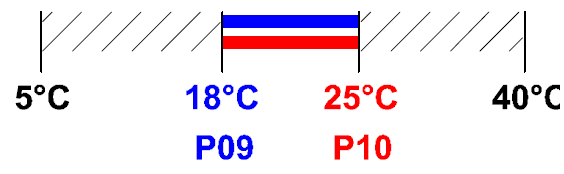
- Cooling setpoint adjustable: 18…25 ℃
- Heating setpoint adjustable: 18…25 ℃
P09≥P10 (energy saving concept)
If the minimum limit P09 is set higher that the maximum limit P10, then:
- The setting range of cooling setpoint is P09…40 ℃ in place of 5…40 ℃.
- The setting range of heating setpoint is 5 ℃…P10 in place of 5…40 ℃.
As a result, the maximum heating setpoint and the minimum cooling setpoint can be limited, thus saving energy and lowering costs.
For 4-pipe applications:
The thermostat runs with the setpoint of the active sequence:
- In heating mode, the heating setpoint is active and adjustable via buttons.
- In cooling mode, the cooling setpoint is active and adjustable via buttons.
Switching from heating to cooling setpoint and vice-versa occurs when the room temperature reaches the adjusted limitation (P09 or P10) of the inactive sequence. e.g. the thermostat is in heating sequence and runs on the heating setpoint. When the room temperature reaches P09, the thermostat switches to cooling mode and runs on the cooling setpoint, provided the room temperature does not drop below P10. Keylock Keylock can be activated or deactivated via parameter P14 when the thermostat is in Comfort and Protection mode. Either full lock (P14=1) or partial lock (P14=2) can be selected. All buttons are disabled if full lock is set. On partial lock, only setpoints can be adjusted.
Operating modes
The following operating modes are available:
Comfort mode![]()
In Comfort mode, the thermostat maintains the setpoint, which can be adjusted via the + and – buttons.
![]() To save energy, the setpoint setting range has a minimum (P09) and maximum limitation (P10).
To save energy, the setpoint setting range has a minimum (P09) and maximum limitation (P10).
Protection mode![]()
When the thermostat is in Protection mode, the related setpoints of heating or cooling setpoints are maintained. They can be adjusted via control parameters P65 and P66. The factory setting for P66 is OFF, indicating the thermostat is not active in Protection (cooling) mode.
Timer with delay Off mode![]()
In timer with delay Off mode, the timer starts counting down according to the hour selected (via parameter P28) after the thermostat is turned ON. When the timer expires, the thermostat automatically turns OFF
- Activation of timer with delay Off mode can be activated in two ways:
- Parameter P28 = 0 (factory setting) When P28 = 0, the delay timer is not active when the thermostat is powered up. To activate the delay timer mode, please press and hold the button for more than 3 seconds.
- Parameter P28 ≠0 When P28 ≠0, the delay timer is active in normal mode whenever the thermostat is turned on.
- Setting of timer with delay Off mode Refers to the Parameter settings.
- Cancellation of timer with delay Off mode Cancel by setting the timer to 0 hour.
Operating mode setting upon power down
If the thermostat is disconnected from AC 230 V power supply and then reconnected, the thermostat returns to the previous operating mode or user settings if P27=0, or remains in Protection (Off) mode if P27=1.
Disposal
The device is considered an electronic device for disposal in accordance with the European Guidelines and may not be disposed of as domestic garbage.

- Dispose of the device through channels provided for this purpose.
- Comply with all local and currently applicable laws and regulations.
Warranty
Technical data on specific applications are valid only together with Siemens products listed under “Equipment combinations”. Siemens rejects any and all warranties in the event that third-party products are used.
Technical data
| Power supply | |
| Operating voltage | AC 230 V (+10%, -15%) |
| Frequency | 50/60 Hz |
| Power consumption | Max. 12 VA |
| Internal fuse (replaceable) | |
| Fuse type | SLOW-BLOW |
| Size | dia. 5.2×20 mm |
| Voltage rating | 250 V |
| Current rating | 6.3 A |
| Outputs | |
| Valve output (RDD510) Y12 (N.C.)/Y14 (N.O.)
Rating |
AC 230 V
5 mA…4(2) A |
| Operational data | |
| Switching differential
– Heating mode – Cooling mode |
0.5…6 K (factory setting: 1 K) 0.5…6 K (factory setting: 1 K) |
| Setpoint setting range (see note below)
– Comfort mode – Protection mode |
5…40 °C OFF, 5…40 °C |
| Built-in room temperature sensor
– Measuring range – Accuracy at 25 °C – Temperature calibration range |
0…50 °C < ±0.5 K – 5.0…+5.0 K |
| Resolution of settings and display
– Temperature setpoints – Current temperature value displayed |
0.5 °C 0.5 °C |
Note: The standard range is 5…40 °C. Customization is available upon request (e.g. 0…50 °C).
| Ambient conditions and protection classification | |
| Safety class | II as per EN 60730-1 |
| Pollution class | II as per EN 60730-1 |
| Degree of protection of housing | IP30 as per EN 60529 |
| Climatic ambient conditions
– Storage as per EN 60721-3-1 – Transport as per EN 60721-3-2 – Operation as per EN 60721-3-3 |
– Class 1K3 – Class 2K3 – Class 3K5 1) |
No condensation is allowed.
| Standards, directives and approvals | |
| EU conformity (CE) | A6V101090515 *) |
| Environmental compatibility | The product environmental declaration (A5W00085405A *) contains data on environmentally compatible product design and assessments (RoHS compliance, materials composition, packaging,
environmental benefit, disposal). |
All documentations can be downloaded from https://www.downloads.siemens.com/download-center/.
| General | |
| Connection terminals | Solid wires or prepared stranded wires: 1×0.4-1.5 mm2 |
| Weight | Mounting frame: 20 g
RDD510 unit with mounting frame: 160 g |
| Color of front housing | White, RAL 9003 Silver, Cool Grey 4C Gold, Gold 453C
Black, Pantone black 7C |
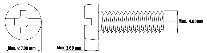
Mounting screws
Diagrams
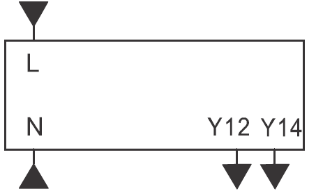
Connection terminals
| RDD510 | |
 |
|
| L, N | AC 230 V power supply, mains and neutral |
| Y12 | Output “Valve”, AC 230 V (NC) |
| Y14 | Output “Valve”, AC 230 V (NO) |
RDD510
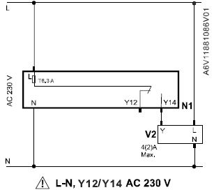
Example 1: with SUA21/3
Example 2: with 3-wire valve
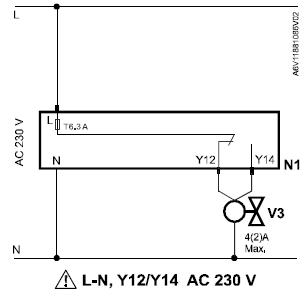
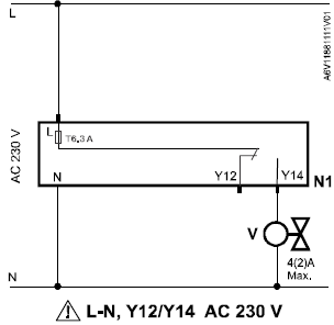
- N1 RDD510
- L, N AC 230 V power supply, mains and neutral
- V1 On/Off valve
- V2 On/Off valve: Siemens SUA21/3
- V3 ON/Off valve: third party 3-wire valve
- Y12 SPDT relay output, normally closed
- Y14 SPDT relay output, normally open
- T 6.3 A Internal fuse (6.3 A), replaceable
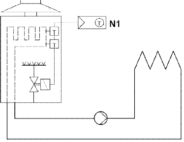
Application examples
| Heating | ||||||
| ● Floor heating
● Radiators ● Wall-hung boilers |
||||||
 |
 |
|||||
| Room thermostat controls the valve of the floor heating or radiator application | Room thermostat directly controls a gas-fired wall-hung boiler | |||||
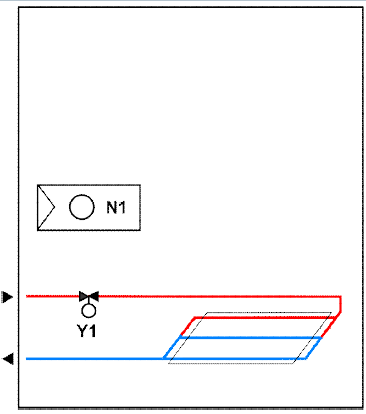
| Cooling | ||||||
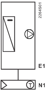 |
||||||
| Room thermostat directly controls cooling equipment | ||||||
| N1 | Room thermostat | Y1 | 2-port valve | E1 | Cooling equipment | |
Dimensions
Dimensions in mm View A View B
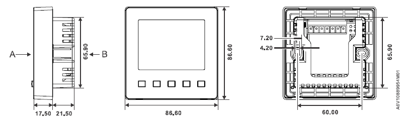 Above are the dimensions for the thermostat and its mounting plate
Issued by
Siemens Switzerland Ltd Smart Infrastructure Global Headquarters Theilerstrasse 1a
- CH-6300 Zug
- Tel. +41 58 724 2424
- www.siemens.com/buildingtechnologies
© Siemens Switzerland Ltd, 2020 Technical specifications and availability are subject to change without notice.
REFERENCE:
DOWNLOAD MANUALS:
SIEMENS RDD510 F Heating or Cooling Room Thermostat Product Specifications Guide
![]()
SIEMENS RDD510 F Heating or Cooling Room Thermostat Product Specifications Guide
Leave a Reply