

Seltron ST2 Digital Room Thermostats

Appearance and description
ST2 is a powerful and efficient modular room thermostat with exchangeable modules. It can be used in heating or (and) cooling systems. It is suitable for radiator, convector and surface heating systems. This manual applies for:
- ST2R – ST2 with relay module
- ST2RDR – ST2 with double relay module
- ST2JV – ST2 with module for Junkers and Vaillant gas boilers
- ST2JVDR – ST2 with module for Junkers and Vaillant gas boilers and auxiliary relay module
- ST2TX – ST2 with module for wireless control
Room thermostat ST2 also enables connection of auxiliary tem-perature sensor1 and remote activation with the telephone1.
LEGEND
![]()
- Hold the key while pressing other keys.
- Hold the key until you hear a beep sound.
- Press and release key.
- Press the key to increase or decrease the value.
1 this option is not available in all ST2 editions
Controlled devices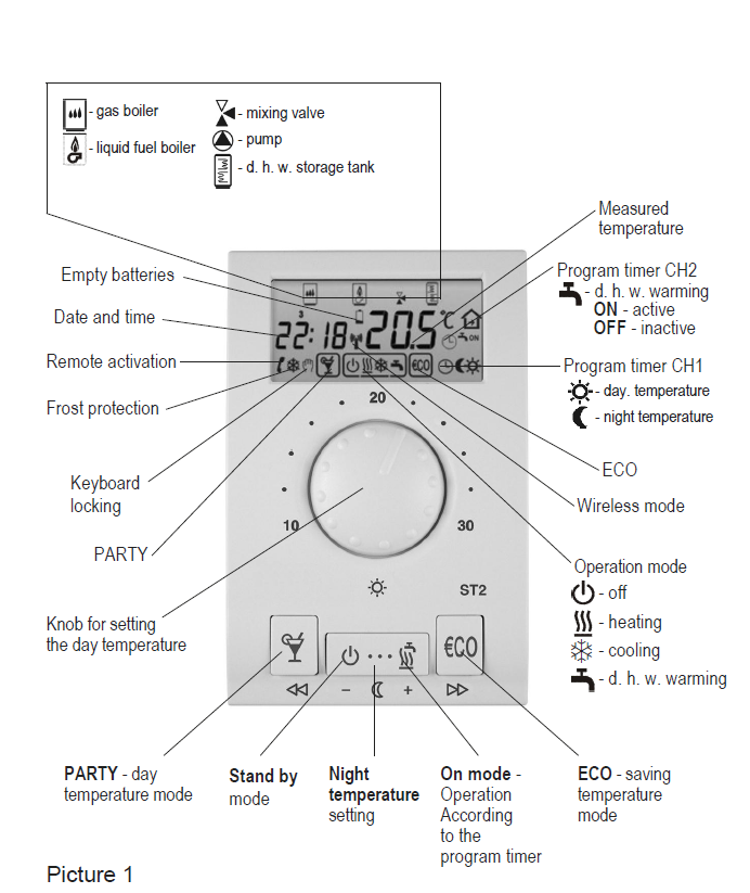
Operating mode selection
Heating activation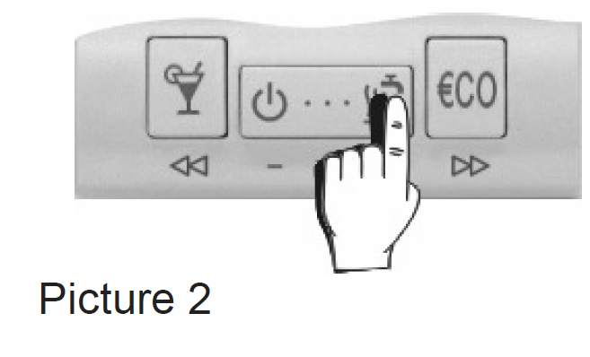
Press the key![]() to select the requested operating mode (Picture 2). The selected operation mode is indicated on display
to select the requested operating mode (Picture 2). The selected operation mode is indicated on display
![]()
- room heating
- room cooling
- domestic hot water warming
Room heating operates according to the program timer CH1, domestic hot water warming operates according to the program timer CH2.
Stand-by
Press the key![]() (Picture 3). On the display appears symbol
(Picture 3). On the display appears symbol![]() .
.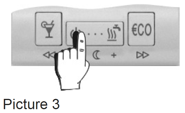
Frost protection remains active
The frost protection temperature is 6 °C and can be changed in program group P1.3 (page 26).
Setting the day and night temperature
Day temperature
Turn the knob to set the requested day temperature between 10 °C and 30 °C (Picture 4).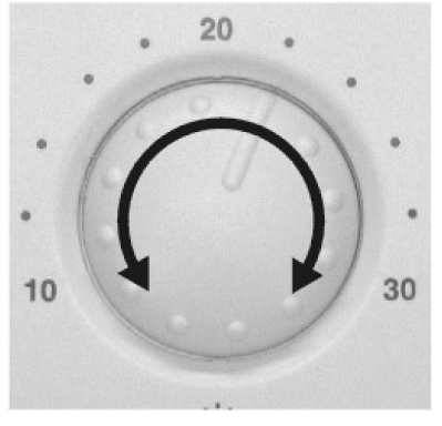
Night temperature
Hold a key ![]() (
(![]() ) for approx. 5 seconds (Picture 5a). Release the key after you hear a beep. Now press key
) for approx. 5 seconds (Picture 5a). Release the key after you hear a beep. Now press key![]() (
(![]() ) or
) or ![]() (
(![]() ) to set the requested night temperature (Picture 5b). To save and quit set-up, press key ( ) once again.
) to set the requested night temperature (Picture 5b). To save and quit set-up, press key ( ) once again.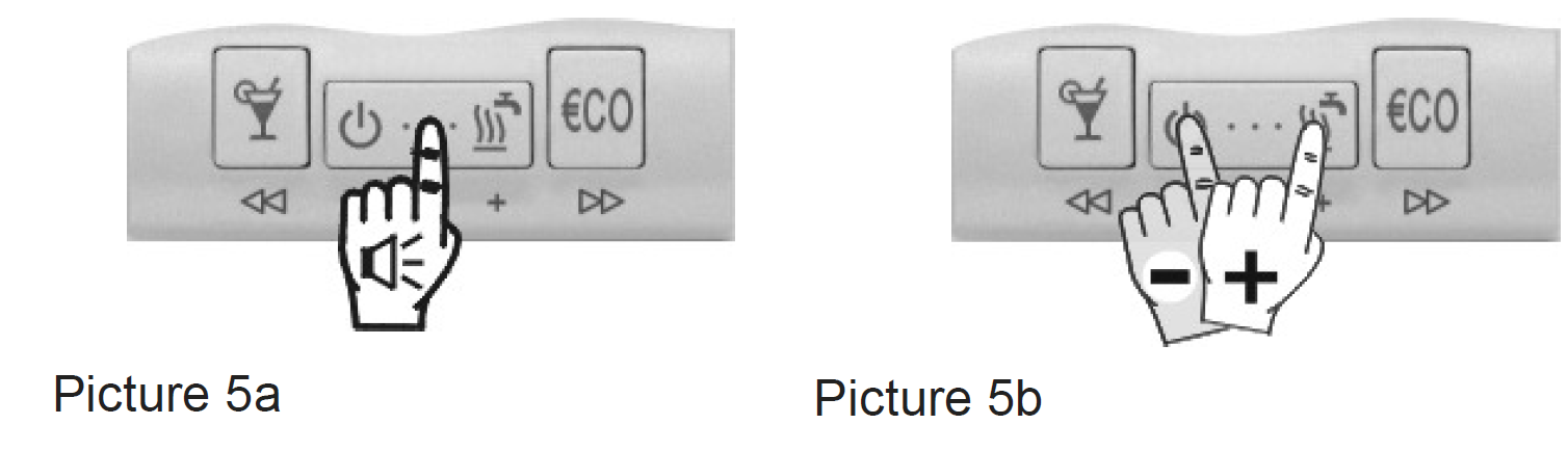
Setting the comfort temperature
Hold the key![]() for 5 seconds (Picture 6a). Use key
for 5 seconds (Picture 6a). Use key ![]() (
( ![]() ) or
) or![]() (
(![]() ) to set the COMFORT temperature between 10 °C and 30 °C (Picture 6b). To save and quit set-up, hold the key
) to set the COMFORT temperature between 10 °C and 30 °C (Picture 6b). To save and quit set-up, hold the key![]() for 5 seconds.
for 5 seconds.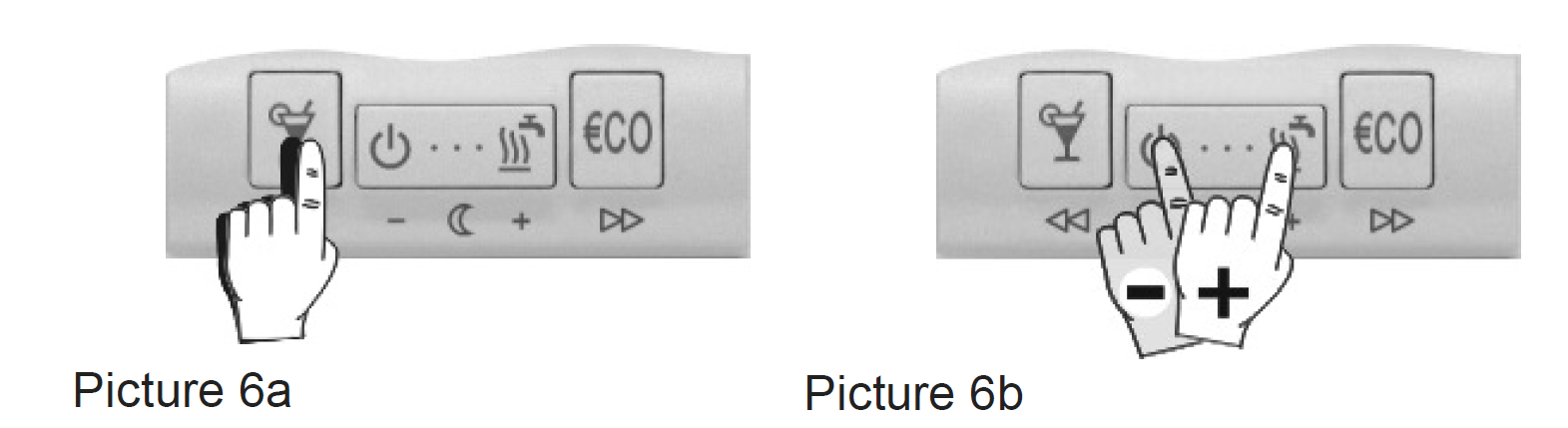
Room heating with the comfort temp. operates according to the program timer CH3 and has precedence over to room heating according to the program timer CH1.
If the comfort heating mode is inactive, the comfort temperature setting is also inactive. The comfort temperature mode is set in program group P1.8 (page 26).
PARTY and ECO operating mode
PARTY – day temperature operation
Press key![]() . Use key
. Use key![]() (
(![]() ) or
) or![]() (
(![]() ) to set the duration of the PARTY mode between 1 and 24 hours. For permanent PARTY mode, select on. To stop PARTY mode at any time, press the key
) to set the duration of the PARTY mode between 1 and 24 hours. For permanent PARTY mode, select on. To stop PARTY mode at any time, press the key![]() .
.
ECO – night temperature operation
Press key![]() . Use key
. Use key ![]() (
(![]() ) or
) or![]() (
(![]() ) to set the duration of the ECO mode between 1 and 24 hours. For permanent ECO mode, select on. To stop ECO mode at any time, press the key
) to set the duration of the ECO mode between 1 and 24 hours. For permanent ECO mode, select on. To stop ECO mode at any time, press the key![]() .
.
The ECO temperature reduction is set in program group P1.2 (page 26).
Holiday mode
Hold the key ![]() for approximately 15 seconds. Release the key after you hear a beep. Use key
for approximately 15 seconds. Release the key after you hear a beep. Use key ![]() (
(![]() ) or
) or ![]() (
(![]() ) to set the duration of the HOLIDAY mode between 1 and 99 days.
) to set the duration of the HOLIDAY mode between 1 and 99 days.
To stop HOLIDAY mode at any time, again hold the key![]() for 15 seconds
for 15 seconds
The HOLIDAY mode temperature is set in program group P1.4 (page 26). Factory pre-setted HOLIDAY temperature is 12 °C.
Setting the accurate time
- Hours
Hold key and press key
 (
( ) or
) or  (
( ) to set the hours (Picture 7).
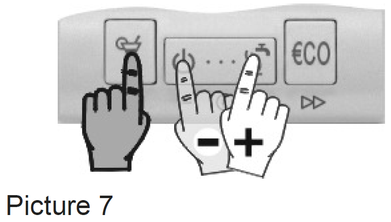
- Minutes
Hold the key and press key ( ) or ( ) to set the minutes (Picture 8).
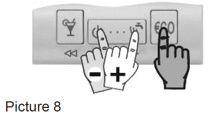
- Day
Hold both keys and , then press key ( ) or ( ) to set the day (Picture 9). The days are marked from 1 to 7. Monday is marked as 1 and Sunday as 7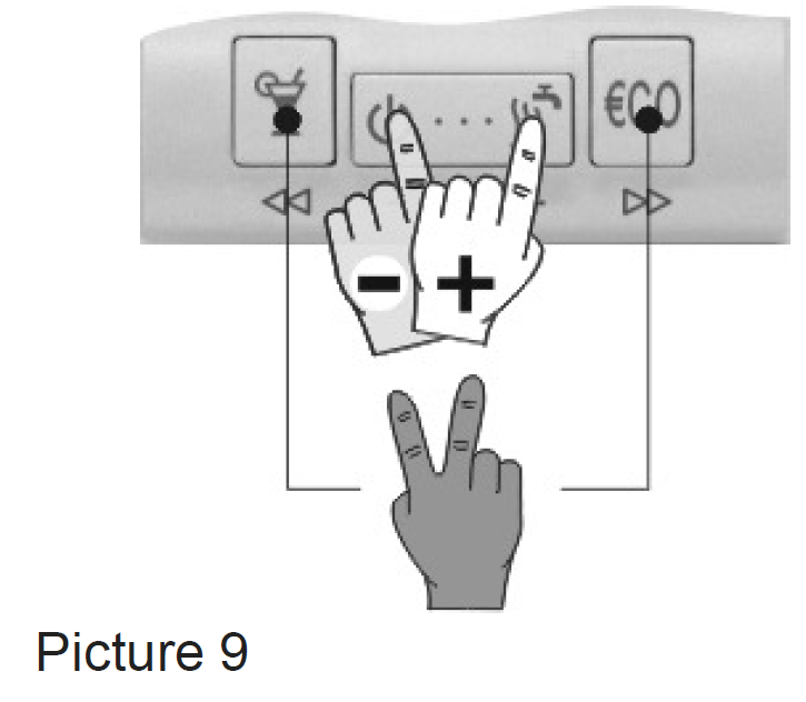
If the ST2, by battery exchange, isn’t functional for a while, the time is set to Monday, 20:00.
Program timer
- The program timer has three channels: CH1, CH2, and CH3.
- CH1 is used for programming the room heating (day/night),
- CH2 is used for programming domestic hot water warming,
- CH3 is used for programming the comfort room heating
Selecting the program channel
Hold the key![]() and press the key
and press the key![]() (Picture 10). Release both keys after you hear a beep. Press key
(Picture 10). Release both keys after you hear a beep. Press key![]() (
(![]() ) or key (
) or key (![]() ) to select the program channel you wish to modify.
) to select the program channel you wish to modify.
Modifying the time program
Press key![]() (
(![]() ) or
) or ![]() (
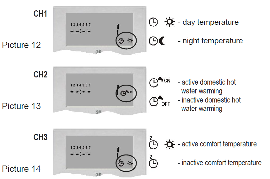
(![]() ) to select the program place that you wish to modify. The display simultaneously writes out the time command, the successive number of the program space (Picture 11) and the switch-on/off command (Pictures 12, 13, and 14).
) to select the program place that you wish to modify. The display simultaneously writes out the time command, the successive number of the program space (Picture 11) and the switch-on/off command (Pictures 12, 13, and 14).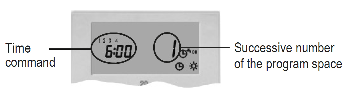
Now press key![]() (
(![]() ). On the display starts to flash day. Press key
). On the display starts to flash day. Press key ![]() (
(![]() ) or
) or![]() (
(![]() ) to set day, then press key
) to set day, then press key![]() (
(![]() ). On the display starts to flash hours. Press key
). On the display starts to flash hours. Press key![]() (
(![]() ) or
) or![]() (
(![]() ) to set hours, then press key
) to set hours, then press key ![]() (
(![]() ). On the display starts to flash minutes. Press key
). On the display starts to flash minutes. Press key ![]() (
(![]() ) or
) or![]() (
(![]() ) to set minutes, then press key
) to set minutes, then press key ![]() (
(![]() ). The display stops flashing. Now is possible to move to the next program space. Press
). The display stops flashing. Now is possible to move to the next program space. Press ![]() (
(![]() ) to move to the next program space or press
) to move to the next program space or press![]() (
(![]() ) to move to the previous program
) to move to the previous program
Every channel in the program timer (CH1, CH2 and CH3) has 32 program spaces. Time commands for day and night temperature mode, time commands for active and inactive d. h. w. warming and time commands for active and inactive comfort temp. mode are successively followed.
Unused time commands are indicated as – -:- – (picture 15). Room thermostat ST2 displays only used program spaces.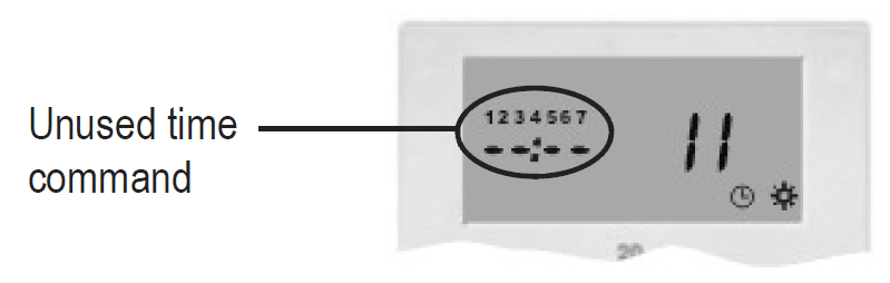
Pre-setted time programs
Room thermostat ST2 has 6 pre-setted time programs for room heating and 6 pre-setted time programs for domestic hot water warming. For each channel CH1 and CH2 is possible to select between 4 fixed (Pr1, Pr2, Pr3, and Pr4) and 2 users set time programs (Pr1 and Pr2 ).
Pre-setted time program selection
Hold the key![]() and by pressing the key
and by pressing the key![]() select the suitable time program (Picture 16). The symbol indicates programs for room heating (CH1), the symbol
select the suitable time program (Picture 16). The symbol indicates programs for room heating (CH1), the symbol![]() indicates programs for domestic hot water warming. (CH2). Te view the time commands in the program, press the key
indicates programs for domestic hot water warming. (CH2). Te view the time commands in the program, press the key ![]() (
(![]() ) or
) or ![]() (
(![]() ).
).
The selected time program always overwrites the previous one. To keep the current time program active, select – – -.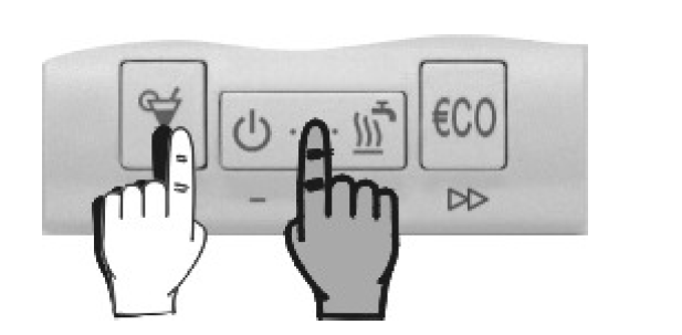
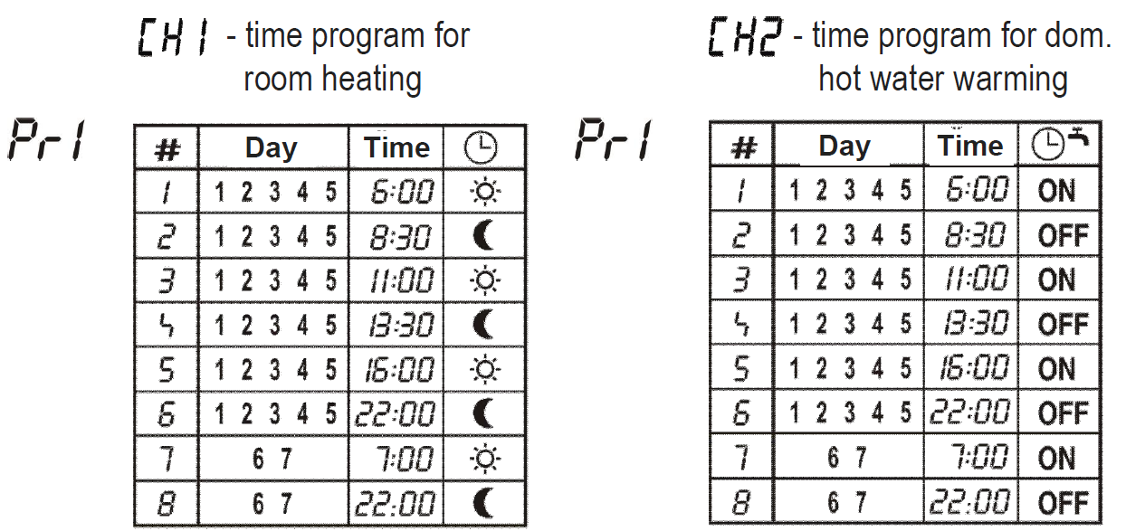
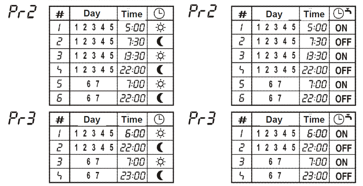
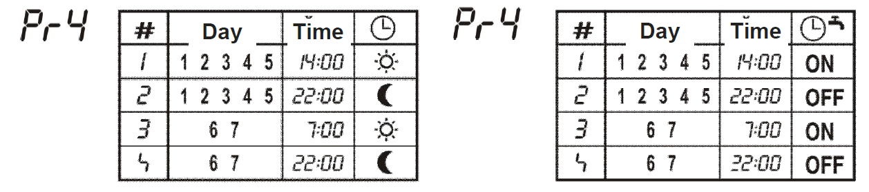
Table 1: Pre-setted time programs Pr1, Pr2, Pr3, Pr4
In the program timer, CH1 and CH2 are factory pre-stored time programs Pr1
User-pre-setted programs Pr1![]() and Pr2
and Pr2![]()
Pre-setted time programs with a symbol![]() can be user modified. These programs can be changed or modified the same way as programs in the program timer (see chapter Modifying the time pro-gram, on page 15).
can be user modified. These programs can be changed or modified the same way as programs in the program timer (see chapter Modifying the time pro-gram, on page 15).
By default is in program Pr1![]() , stored program Pr1, and for program Pr2
, stored program Pr1, and for program Pr2![]() , program Pr3.
, program Pr3.
Anti-legionaries disease program
In order to protect against legionaries disease, this room unit has a special function that warms the d. h. w. over 63 °C.
The function is activated with a five-minute ON interval in the program timer (CH2).
Example :
| Day | ON | OFF |
| Mo-Fr | 6:00 | 8:30 |
| Mo-Fr | 11:00 | 13:30 |
| Mo-Fr | 16:00 | 22:00 |
| Fr | 5:00 | 5:05 |
| Sa-So | 6:00 | 20:00 |
The ST2 will warm the d. h. w. over 63 °C every Friday at 5 a. m.. If no d. h .w. temperature sensor is connected to the room there-most will warm the d. h. w. for 2 hours.
We suggest you, to run the anti-legionaries program once in a week during the nighttime.
Manual d. h. w. warming activation
Hold key ![]() for 5 seconds. Release the key after you hear a beep.
for 5 seconds. Release the key after you hear a beep.
Manual domestic hot warming is automatically deactivated when requested d. h. w. temperature is reached or at the latest after 1 hour.
Thermostat locking
Hold the key![]() for 15 seconds. Release the key after you hear a beep. The symbol
for 15 seconds. Release the key after you hear a beep. The symbol![]() indicates a locked room unit. To unlock the ST2, again hold key
indicates a locked room unit. To unlock the ST2, again hold key![]() for 15 seconds.
for 15 seconds.
Setting or modifying the parameters by locked ST2 isn’t possible or it’s limited.
ST2 locking is set in service group S1.9 (page 29).
Selection between heating or cooling
To switch over between heating and cooling and in reverse, hold the key![]() for approximately 10 seconds (Picture 17). Release the key after you hear a beep. The display writes out active mode for a few seconds, HEA – heating or COO – cooling (Picture 18).
for approximately 10 seconds (Picture 17). Release the key after you hear a beep. The display writes out active mode for a few seconds, HEA – heating or COO – cooling (Picture 18).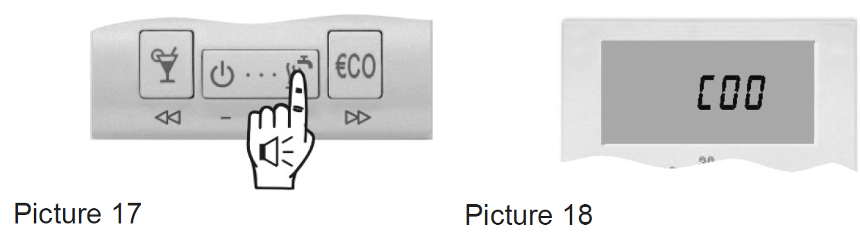
Remote control
With the telephone is possible to remotely activate the day temperature mode. Remote activation is signalized with the symbol![]() . This function is set in Program Group P3 (page 27). For analog telephone line device, G1-D is available.
. This function is set in Program Group P3 (page 27). For analog telephone line device, G1-D is available.
Auxiliary temperature sensor – temperature overview
The temperature of the additional temperature sensor is displayed if in the normal display mode the command “Escape˝ is applied, . Only if the additional temperature sensor is connected.
Command to quickly save and quit (Escape)
Every time you wish to quick store and quit set-up, hold the key![]() and press key
and press key![]() . Release both keys after you hear a beep.
. Release both keys after you hear a beep.
All modifications made, are stored. This command isn’t valid for program and service settings.
Battery replacement
Empty batteries are indicated with the symbol![]() on display. We suggest the battery replacement every 2 years. ST2 is supplied with two alkaline batteries 1.5 V type AAA. The battery socket is inside the ST2. To remove the thermostat from the wall plate, do the following. Hold the thermostat in the height of keys and pull it towards yourself (Picture 19 – OPEN). After battery exchange, put ST2 back on the wall plate, by doing the following. Hook ST2 on top and push it with the bottom towards the wall plate (Picture 19 – CLOSE).
on display. We suggest the battery replacement every 2 years. ST2 is supplied with two alkaline batteries 1.5 V type AAA. The battery socket is inside the ST2. To remove the thermostat from the wall plate, do the following. Hold the thermostat in the height of keys and pull it towards yourself (Picture 19 – OPEN). After battery exchange, put ST2 back on the wall plate, by doing the following. Hook ST2 on top and push it with the bottom towards the wall plate (Picture 19 – CLOSE).
Battery exchange should be done within 20 seconds. In another case you will have to set the accurate time again.
All data and settings are joined into 16 groups:
- CH1 ············ program timer for room heating
- CH2 ············ program timer for d. h. w. warming
- CH3 ············ program timer for comfort room heating
- d1 ·············· room thermostat data
- P1 ·············· Program group 1
- P2 ·············· Program group 2
- P3 ·············· Program group 3
- S1 ·············· Service group 1
- S2 ·············· Service group 2
- S3 ·············· Service group 3
Menu
To enter the menu, hold the key![]() and press the key
and press the key![]() (Picture 26). Release keys after you hear a beep. The display writes out the first group CH1.
(Picture 26). Release keys after you hear a beep. The display writes out the first group CH1.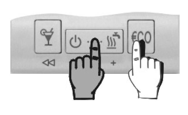
Menu navigation
In the menu, keys have new meanings, marked below them (Picture 21). To move between the groups press key![]() (
(![]() ) to move to the left and key
) to move to the left and key ![]() (
(![]() ) to move to the right (Picture 22). To move within the group press key
) to move to the right (Picture 22). To move within the group press key![]() (
(![]() ) to move down between the lines and key
) to move down between the lines and key![]() (
(![]() ) to move up between the lines. For your better understanding, all the lines are marked. The first two symbols mark the group and the third symbol successive number of the line in the group(Picture 23).
) to move up between the lines. For your better understanding, all the lines are marked. The first two symbols mark the group and the third symbol successive number of the line in the group(Picture 23).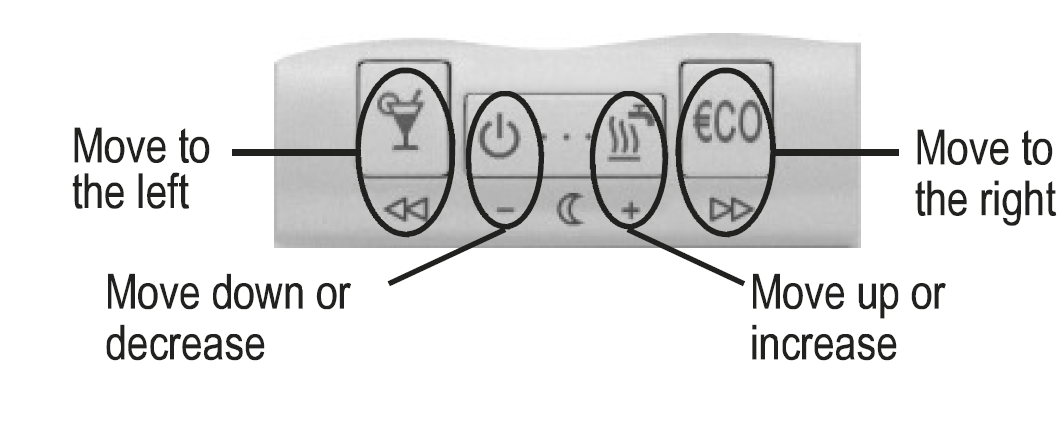
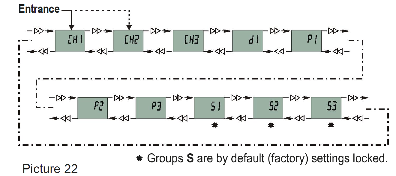
Group locking is setted in Service group S3 (page 30).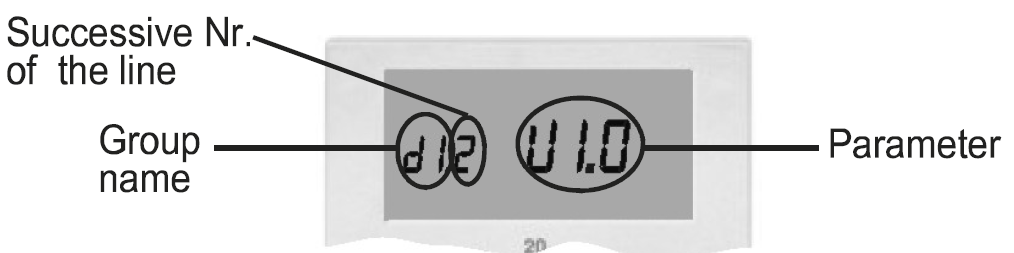
- Program timer for room heating CH1
For changing the time program see chapter Modifying the time program (page 15). - Program timer for domestic hot water warming CH2
For changing the time program see chapter Modifying the time program (page 15). - Program timer for comfort room heating CH3
For changing the time program see chapter Modifying the time program (page 15).
Room thermostat data d1
This group is sort of ST2. ID. In this group are information about ST2, modifying isn’t possible. The information are displayed in the following order:
- [d1.1] Room thermostat type (ST2)
- [d1.2] Software version
- [d1.3] Heating or cooling
- [d1.4] ED constant or actuator speed or controlled device
- [d1.5] Built-in temperature sensor calibration
- [d1.6] Auxiliary temperature sensor calibration
- [d1.7] Selected controlled system
- [d1.8] Battery voltage
- [d1.9] Reserved
Program group P1
Program group P1 is used for the thermostat user settings. To change the selected parameter, hold key![]() for approximately 5 seconds. The parameter starts to flash. Press key
for approximately 5 seconds. The parameter starts to flash. Press key ![]() (
(![]() ) or
) or![]() (
(![]() )to set the parameter value. To store the setted value, again hold key
)to set the parameter value. To store the setted value, again hold key ![]() for approximately 5 seconds
for approximately 5 seconds
This procedure, for modifying the parameter, is the same for all program and service groups
Group P1 contains the following parameters; (factory setting):
- [P1.1] Night temperature (6 °C ÷ 26 °C); (17 °C)
- [P1.2] temp. reduction in ECO mode (0 °C ÷ -9 °C); (-3 °C)
- [P1.3] frost protection temperature (2 °C ÷ 20 °C, – – – deactivated, P – temp. is set with the knob); (6 °C)
- [P1.4] holiday mode temperature (5 °C ÷ 25 °C); (12 °C)
- [P1.5] ED constant (5 min ÷ 50 min, – – – deactivated); (20 min)
- [P1.6] Display of controlled device (- – – none, 1 – oil boiler, 2 – gas boiler, 3 – actuator, 4 – pump); (1)
- [P1.7] Temperature sensor calibration (-2 °C ÷ 2 °C); (6 °C)
- [P1.8] Comfort mode temp. (10 °C ÷ 30 °C, – – – inactive); (- – -)
- [P1.9] Periodic activation of pumps and mixing valve (- – – deactivated, 1 – activated) 1; (1).
1 Activation is every Saturday at:
- 21:01 – mixing valve or circulation pump activation
- 21:02 – d. h. w. circulation pump activation
Program group P2
- Program group P2 is intended for additional thermostat settings.
In program group P2 are the following parameters; (factory setting):
- [P2.1] Domestic hot water temperature (20 °C ÷ 80°C); (55 °C)
- [P2.2] Switch-on hysteresis for domestic hot water (0.5 °C ÷ 10 °C); (4°C)
- [P2.3] Minimal boiler temperature (20 °C ÷ 70 °C); (50 °C)
- [P2.4] Maximal boiler temperature (50 °C ÷ 97 °C); (90 °C)
- [P2.5] Naximal stand-pipe temperature (25 °C ÷ 95 °C); (65 °C)
- [P2.6] Maximal floor temperature (10 °C ÷ 40 °C); (30 °C)
- [P2.7] Beeper mode (- – – silent, 1 – by typing, 2 – by program
Timer changeover, 3 – by typing and program timer changeover); (1) - [P2.8] Radio channel number (1 ÷ 16); (1)
- [P2.9] Radio module type (1 – AM module, 2 – FM module); (1)
- [P2.10] Display of measured temperatures (1 – built-in sensor,
- 2 – auxiliary sensor, 3 – both sensors – alternating,
- 4 – display of requested (set) temperature,
- 5 – return-pipe temperature sensor); (1)
- [P2.11] Actuator speed (1 ÷ 8 min); (2 min)
- [P2.12] Tvmin in cooling mode (10 ÷ 24 °C); (16 °C)
Program group P3
- Program group P3 is intended to set the remote control with the telephone.
In program group P3 are the following parameters; (factory setting):
- [P3.1] Requested temperature (10 °C ÷ 30 °C, P – temperature setted with the knob); (P)
- [P3.2] Operation mode (1 – room heating
- 2 – domestic hot water warming, 3 – room heating and
- d. h. w. warming, 4 – changeover to cooling mode,
- 5 – Party mode 1); (3)
Service group S1
Service group S1 is intended for thermostat service settings. In program group S1 are the following parameters; (factory setting):
- [S1.1] Controlled heating system (1 – heating circuit (ON / OFF control),
- 2 – heating circuit (ON / OFF control) and dom. hot water,
- 3 – heating circuit (3-point control),
- 4 – heating circuit (ON / OFF control) + boiler with built-in domestic hot water storage tank,
- 5 – floor heating,
- 6 – domestic hot water,
- 7 – gas boiler Junkers or Vaillant (flame power modulation),
- 8 – gas boiler Junkers or Vaillant and d. h. w. circulation),
- 9 – heating circuit (ON / OFF control) and cooling; (depends on installed module – see Table 2)
- [S1.2] Auxiliary sensor (- – – no sensor, 1 – room temp. sensor,
- 2 – outdoor temp. sensor, 3 – d. h. w. temperature sensor,
- 4 – floor temp. sensor, 5 – boiler temp. sensor,
- 6 – stand-pipe temperature sensor) (depends on installed module – see Table 2)
- [S1.3] Room temperature (1 – built-in sensor, 2 – auxiliary sensor,
- 3 – min. measured temperature, 4 – max. measured temperature,
- 5 – average temperature); (1 °C)
- [S1.4] Auxiliary temperature sensor calibration (-2 °C ÷ 2 °C); (0 °C)
- [S1.5] Measured temp. roundup (0.1 °C, 0.2 °C, 0.5 °C, 1.0 °C) ; (0,5 °C)
- [S1.6] Heating optimisation 1 (- – – deactivated, 1 – activated); (2)
- [S1.7] Controlling algorithm (1 – P-controller, 2 – PI-controller); (P)
- [S1.8] Pre-setted time programs – selection (- – – no selection,
- 1 – fixed only,
- 2 – user programs only,
- 3 – fixed and user progr.); (3)
- [S1.9] Thermostat locking (- – – no locking, 1 – no locking, but a limited function of key, 2 – enabled key Party and knob,
- 3 – enabled only key Party, 4 – full lock); (2)
- [S1.10] Relay output timeout – delay (- – – none, 1 ÷ 5 min); (- – -)
1 Heating optimization: ST2 automatically calculates the switch-on time and at set time (night-day changeover) the requested temperature is already reached.
Service group S2
Service group S2 is intended for additional thermostat service settings. In program group S2 are the following parameters; (Factory setting):
- [S2.1] Min. scale for temperature setting (0 °C ÷ 90 °C); (10 °C)
- [S2.2] Max. scale for temperature setting (10 °C ÷ 90 °C); (30 °C)
- [S2.3] Minimal temperature setting – limitation (0 °C ÷ 90 °C, – – – no limitation); (- – -)
- [S2.4] Maximal temperature setting – limitation (10 °C ÷ 90 °C, – – – no limitation); (- – -)
- [S2.5] Thermostat hysteresis (± 0.2 °C ÷ ± 10 °C); (± 0.2 °C)
- [S2.6] P-zone (± 0.5 °C ÷ ± 10 °C) (± 0.7 °C)
- [S2.7] Timer accuracy correction (-5 sec/day ÷ 5 sec/day); (0 sec/day)
- [S2.8] Differential constant (0.1 ÷ 10)1; (1)
- [S2.9] Proportional constant (0.1 ÷ 10)1; (1)
- [S2.10] Integral constant (0.1 ÷ 10)1; (1)
Service group S3
Service group S3 is intended for special thermostat settings.
In program group S3 are the following parameters:
- [S3.1] Group locking (- – – no locking,
- locked are groups S,
- locked are groups S and P,
- locked complete menu); (1)
Access to parameter S3.1 is possible in the following way. Hold key for 20 seconds (picture 24). Release the key after you hear a beep. On the display appears parameter (S3.1). Now it’s possible to modify this or any other parameter.
1 Parameter S2.8, S2.9, and S2.10 are intended only for heating circuits with 3-point control
Radio connection – test mode for ST2TX
Check if your receiver has the same radio channel number as settled in parameter S2.8 on ST2TX. Now activate test mode. Hold key and press and hold the key for 5 seconds (picture 25). Release the keys after you hear a beep.
Signal power indication by receivers RX22, versions up to V1.9
If the radio connection is established, R1 is activated and deactivated every 2 seconds. Receiver every 10 seconds lowers the reception intention, which is signalized with the light R2. Radio connection will operate without interceptions if R1 is activated and deactivated also by lowered signal intensity.
Signal power indication by receivers RX22, version V2.0 or higher
If the radio connection is established, R1 is activated and deactivated every 2 seconds. Signal light R2 indicates the signal intensity with flashing. Signal intensity is indicated with 1 to 5 flashes. The radio connection will operate without interruptions if the light R2 flashes at least 2 times.
Test mode automatically expires after 5 minutes. You can also end it by using the command ”Escape”.
Factory settings – ST2 reset
To restore the factory settings hold keys![]() and
and![]() for approx. 20 seconds (Picture 26). Release keys after you hear a beep
for approx. 20 seconds (Picture 26). Release keys after you hear a beep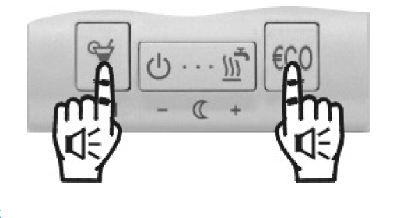
Controlled heating system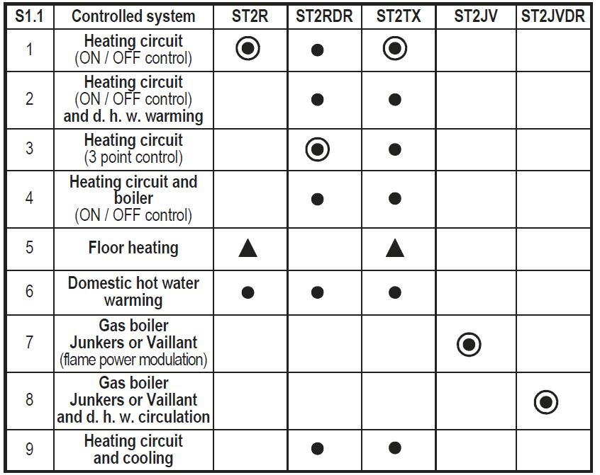
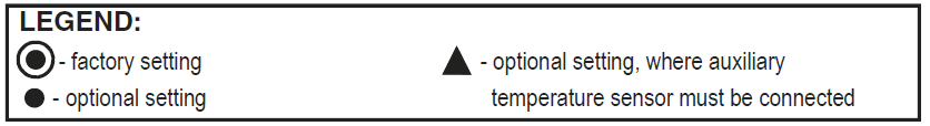
Table 2: Possible applications for particular modules
- For the floor heating system, an auxiliary temperature sensor must be connected.
- The thermostat automatically detects the connected module and selects the default controlled heating system for this module.
Place of mount
The place of the mount is very important for proper ST2 operation. Suitable places are inner walls, which aren’t sun lighted or exposed to sources of heat and wind. ST2 should be mounted approximately 150 cm above the floor (Picture 27).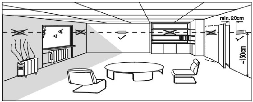
Wall plate mount 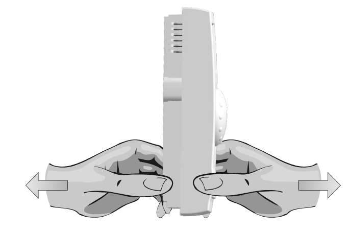
Remove the ST2 from the wall plate, by doing the following. With one hand hold ST2 in the height of the keys and with the other hand the wall plate. Now pull them apart (Picture 28).
Unscrew and temporarily remove the protection cover (Picture 29). The room thermostat is intended for wall mounting. In case you don’t have installed a flush box, tear away the drilling template from the package and mark drilling holes. Use enclosed screws to fasten the wall plate on the wall (Picture 30). After you have done connecting the wires (see chapter Connecting the wires), screw back the protection cover. Now put ST2 back onto the base by doing the following. Hook ST2 on top of the wall plate and push it with the bottom towards the wall plate (Picture 19- CLOSE).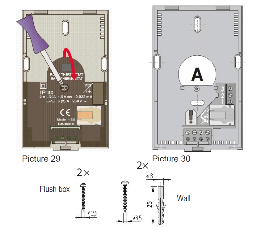
Wires connection
WARNING: Mounting and wiring connections must be done by a qualified installer or authorized company. Local regulations or VDE 0100 and EN IEC 60364 regulations for electrical installations must be considered by doing the wiring connections.
Bring the wires through the opening in the bottom of the wall plate (Picture 30-position A). How to connect the module is detailed and described on pages 115 to 133.
Connecting the auxiliary temperature sensor
Always connect the auxiliary tem-perature sensor into the connector terminals a and b on the wall ST2 plate (Picture 45). Set the parameters for this sensor in service group S1.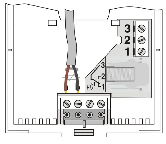
- If a wireless module (TX) is installed, the connection of the auxiliary temperature sensor isn’t possible.
On the ST2 only MURATA-type sensors can be connected. - These sensors are: outdoor sensor AF/M, room sensor PS10-12/M, and immersion sensor TF/M.
Error reports
Sensor malfunction
If auxiliary temp. the sensor is in a short circuit, the display writes out![]()
If the auxiliary sensor is disconnected, the display writes out![]()
ST2R – ST2 with relay module R
With a room thermostat ST2 is possible to control:
- direct heating circuit pump
- boiler control
- heating circuit with mixing valve
- gas boiler
- electric floor heating
- domestic hot water warming
The table on page 115 shows parameter S1.1 settings for thermostat ST2R.
ST2RDR – ST2 with double relay module RDR
With a room thermostat, ST2RDR is possible to control:
- direct heating circuit
- direct heating circuit and domestic hot water warming
- indirect heating circuit – 3-point control
- D. h. w. warming
- direct heating circuit and boiler with built-in domestic hot water storage tank (- direct heating circuit and cooling)
The table on page 122 shows parameter S1.1 settings for thermo-stat ST2RDR.
ST2TX – ST2 with relay module R with module for wireless control TX
- ST2TX enables wireless control for 9 different heating systems (see Table on page 23). The receiver should be mounted in the near of controlled device.
- The thermostat and receiver must have the same radio channel Nr. (setting P2.8, page 27).
- Set the controlled heating system in service group S1.1 (page 28) (default factory setting is 1).
- For connecting the RX22 see the Receiver manual.
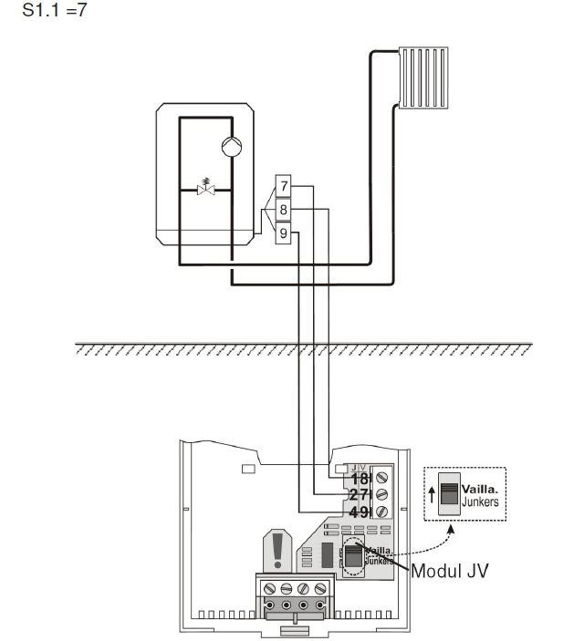
ST2JV – ST2 with module for gas boilers JV
With a room thermostat, ST2JV is possible to control:
- flame power by Junkers gas boilers
- flame power by Vaillant gas boilers
The table on page 128 shows parameter S1.1 settings for thermostat ST2JV.
ST2JVDR – ST2 with module for gas boilers JV and auxiliary relay module DR
With ST2JVDR is possible to control:
- flame power by Junker gas boilers and domestic hot water circulation
- flame power by Vaillant gas boilers and domestic hot water circulation
The table on page 131 bellow shows parameter S1.1 settings for thermostat ST2JVDR.
Technical data
- Model: ……………………………………… ST2
- Operation mode: ……………………….. P – regulator (ON / OFF), sliding mode or PI – controller (3 point control)
- Power supply: …………………………… 2 batteries LR03, size AAA
- Relay output:…………………………….. 230 V ~ / 6 (3) A
- JV module: ……………………………….. 24 V output
- Radio module:…………………………… 433.92 MHz, modulation OOK
- Consumption:……………………………. I= 0,022 mA; P= 0,066 mW
- Temp. sensor type: ……………………. Murata NTC
- Degree of protection: …………………. IP 30 by EN 60529
- Safety class: …………………………….. II by EN 60730-1
- Temperature control class:
- ST2R, ST2RDR, ST2TX ………… IV
- ST2JV, ST2JVDR …………………. V
- Housing: ………………………………….. ABS thermoplast, white
- Dimensions (l × w × h): ………………. 72 × 32 × 112 mm
- Weight: ……………………………………. 150 g
Conformity with standards and directives
Room thermostats ST2 meet the requirements and rules of the following directives:
- LVD: Low voltage directive 2014/35/EC,
- EMC: Directive for Electromagnetic compatibility 2014/30/EC,
- RoHS II: Directive for hazardous substances in electric and electronic appliances 2011/65/EC,
- R&TTE: Directive for radio and telecommunications terminal equipment 1999/5/EC.
PRODUCT DESCRIPTION:
Room thermostat
MODEL:
ST2R, ST2RDR, ST2TX, ST2JV, ST2JVDR
APPLIED STANDARDS:
- EN60730-1:2001, EN60730-1:2001/A2:2009,
- EN60730-2-9:2011,EN 301 489-3:2000,
- EN 300 220-3:2000, EN 60950:1992,
- EN 60950:1992/A1:1993, EN 60950:1992/A2:1993,
- EN 60950:1992/A3:1995, EN 60950:1992/A4:1997.
Disposal of Old Electrical & Electronic Equipment
Disposal of Old Electrical & Electronic Equipment (Applicable in the European Union and other European countries with separate collection systems)
This symbol on the product or on its packaging indicates that this product shall not be treated as household waste. Instead it shall be handed over to the applicable collection point for the recycling of electrical and electronic equipment. By ensuring this product is disposed of correctly, you will help preventpotential negative consequences for the environment and human health, which could otherwise be caused by inappropriate waste handling of this product. The recycling of materials will help to conserve natural resources. For more detailed information about recycling of this product, please contact your local city office, your household waste disposal service or the shop where you purchased the product.
Schemes
ST2R
| Type | Description | S1.1 |
|
ST2R |
Boiler control (picture 31) |
1 |
|
ST2R |
Direct heating circuit pump (picture 32) |
1 |
|
ST2R |
Heating circuit with mixing valve (picture 33) |
1 |
|
ST2R |
Gas boiler (picture 34) |
1 |
|
ST2R |
Electric floor heating (picture 35) |
5 |
|
ST2R |
Domestic hot water warming (picture 36) |
6 |
ST2R default setting for parameter S1.1=1.
Boiler Control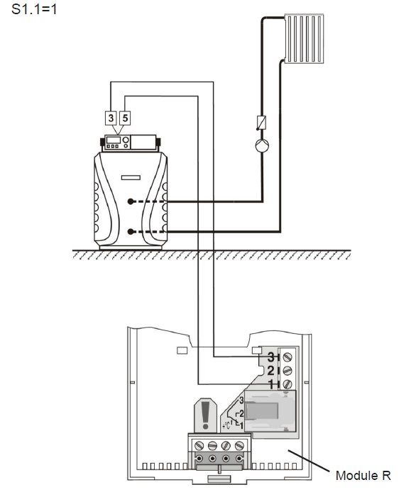
Direct heating circuit pump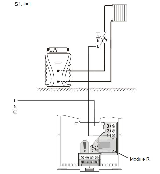
Heating circuit with mixing valve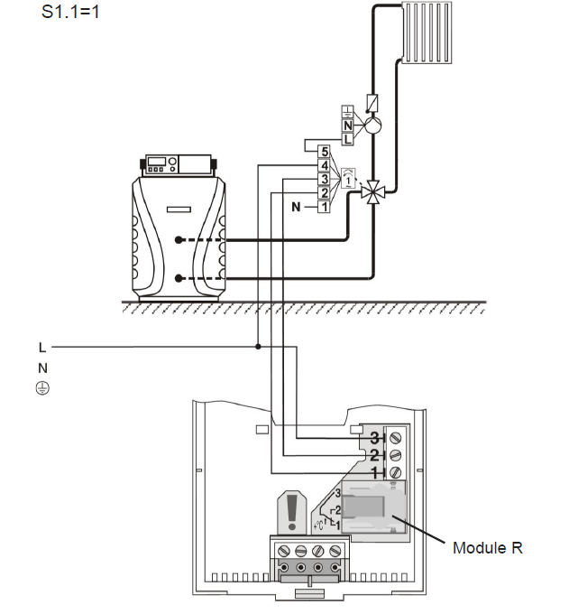
Gas Boiler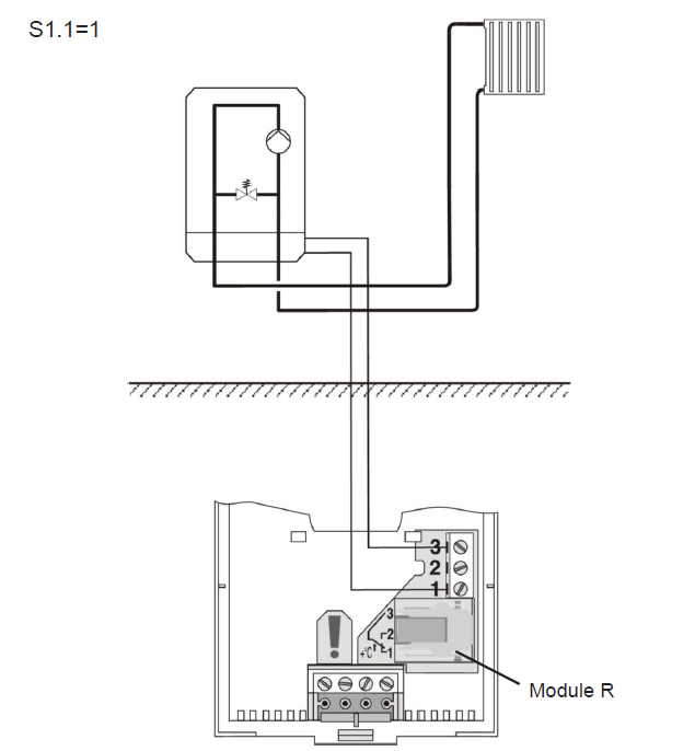
Electric floor heating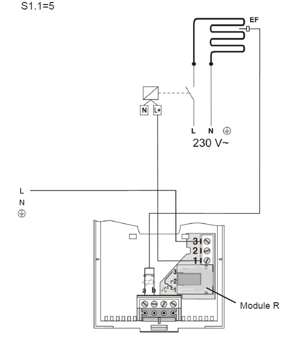
Domestic hot water warming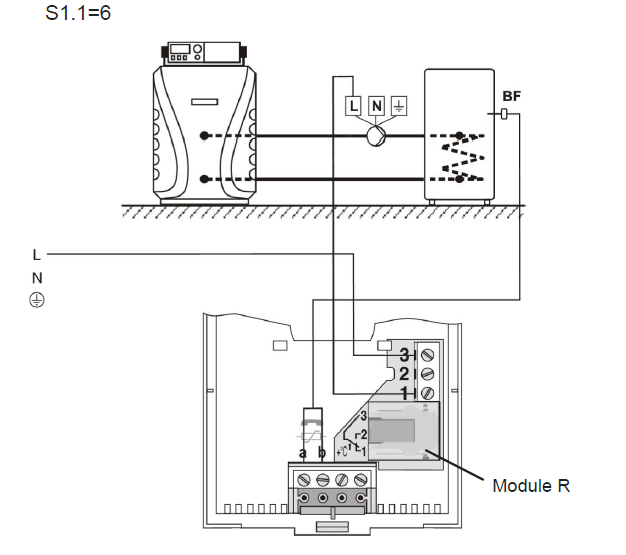
ST2RDR
| Type | Description | S1.1 |
|
ST2RDR |
Direct heating circuit (picture 37) |
1 |
|
ST2RDR |
Direct heating circuit and domestic hot water warming (picture 38) |
2 |
|
ST2RDR |
Indirect heating circuit – 3-point control (picture 39) |
3 |
|
ST2RDR |
Direct heating circuit and boiler with built in domestic hot water storage tank 1 (picture 40) |
4 |
|
ST2RDR |
D. h. w. warming (picture 41) |
6 |
|
ST2RDR |
Direct heating circuit and cooling (picture 42) |
9 |
ST2RDR default setting for parameter S1.1=2.
1 Boiler is activated when there is need for domestic hot water.
Direct heating circuit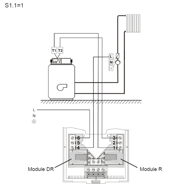
Direct heating circuit and domestic hot water warming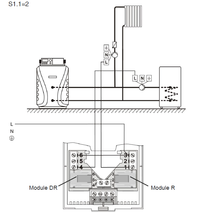
Indirect heating circuit – 3 point control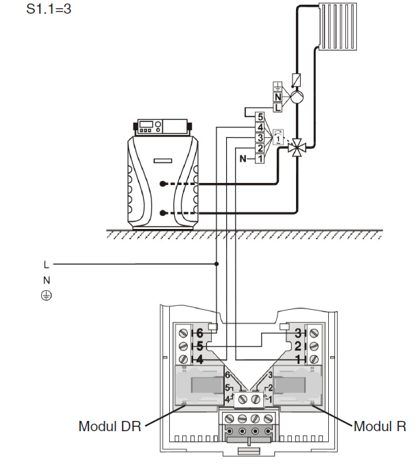
Direct heating circuit and boiler with built in domestic hot water storage tank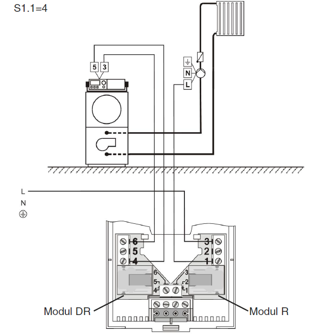
D. h. w. warming 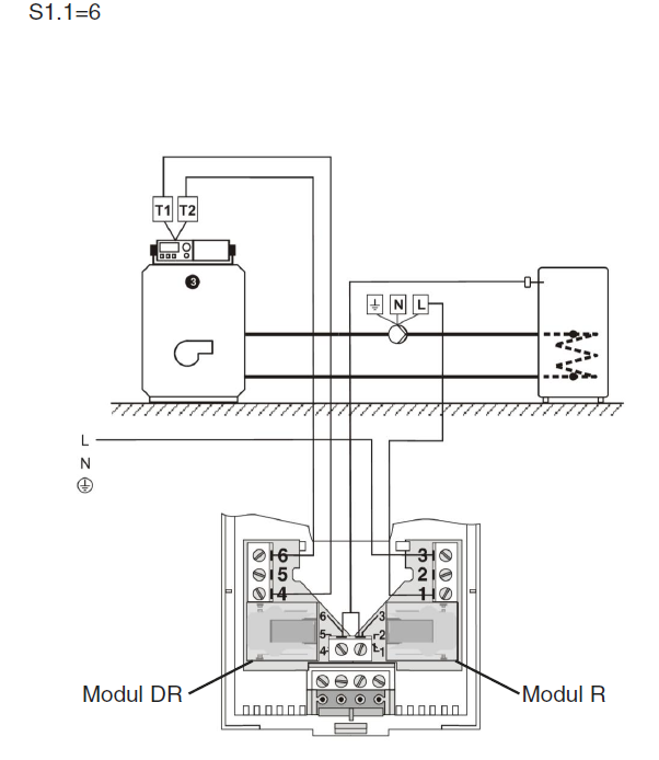
ST2JV
| Type | Description | S1.1 |
|
ST2JV |
Gas boiler Junkers (picture 41) |
7 |
|
ST2JV |
Gas boiler Vaillant (picture 42) |
7 |
ST2JV default setting for parameter S1.1=7.
Gas boiler Junkers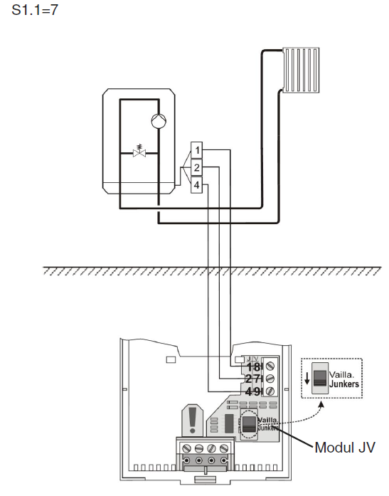
ST2JVDR
| Type | Description | S1.1 |
|
ST2JVDR |
Gas boiler Junkers and domestic hot water circulation (picture 44) |
8 |
|
ST2JVDR |
Gas boiler Vaillant and domestic hot water circulation (picture 45)
|
8 |
ST2JV default setting for parameter S1.1=7.
D. h. w. warming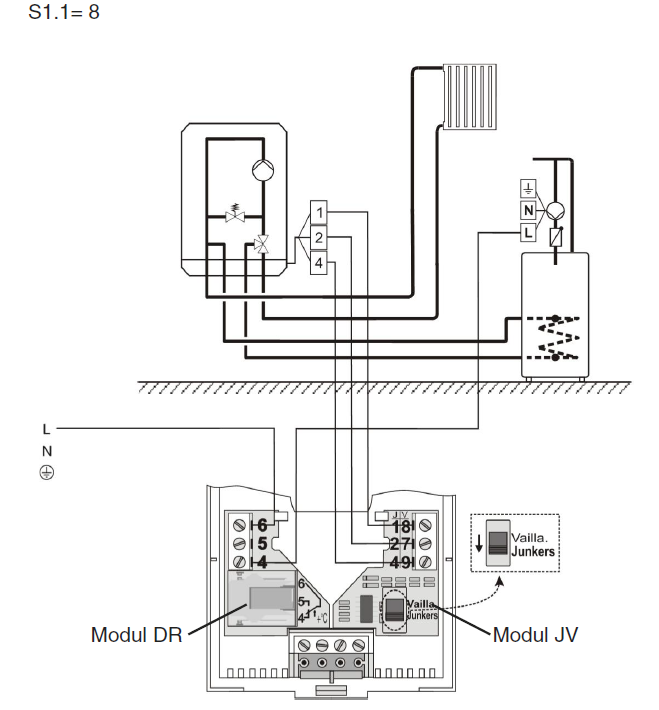
Gas boiler Junkers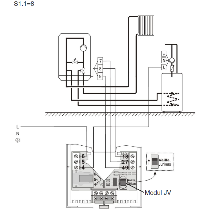
We reserve the right for changes and improvements
Reference
Download Manual:
Seltron ST2 Digital Room Thermostats USER MANUALS

Leave a Reply