
Robertshaw RS9210 Programmable Thermostat
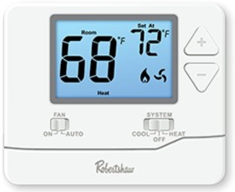
Thank you for purchasing a Robertshaw® thermostat. This manual will describe how to install and test the Robertshaw RS9210 thermostat.
Thermostat System Types
| Gas, Oil, or Electric Heat with Air Conditioning |
| Heat Pumps (with or without auxiliary or emergency heat) |
| Multi-Stage Systems |
| Heat-Only, including for Floor and Wall-Furnace |
| Cool-Only |
| 750 Millivolt Heating Systems |
Power Options
- Battery Power
- Hardwire (Common Wire)
IMPORTANT SAFETY INFORMATION WARNING
- Always turn off power at the main power source by unscrewing the fuse or switching the circuit breaker to the off position before installing, removing, cleaning, or servicing the thermostat.
- Read all of the information in this manual before installing or programming this thermostat.
- This is a 24V AC low-voltage thermostat. Do not install on voltages higher than 30V AC.
- All wiring must conform to local and national building and electrical codes and ordinances.
- Do not short (jumper) across terminals on the gas valve or at the system control to test installation. This will damage the thermostat and void the warranty.
INSTALLATION LOCATION
Install the thermostat 4 to 5 feet above the floor in an area with good air circulation and average temperature. For new installations, mount the thermostat on an inside wall, 4-5 feet above the floor. Do not install the thermostat in the following locations:
- Behind a Door
- In a Corner
- Near Air Vents
- In Direct Sunlight
- With an Outside Wall Behind the Thermostat
- Near any Heat or Steam Generating Fixtures
- Near any Concealed Pipes or Chimneys
Installation at these locations will affect thermostat operation.
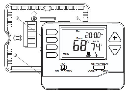
THERMOSTAT QUICK REFERENCE
Getting to know your thermostat
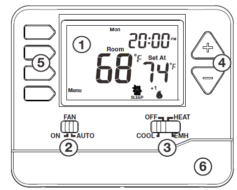
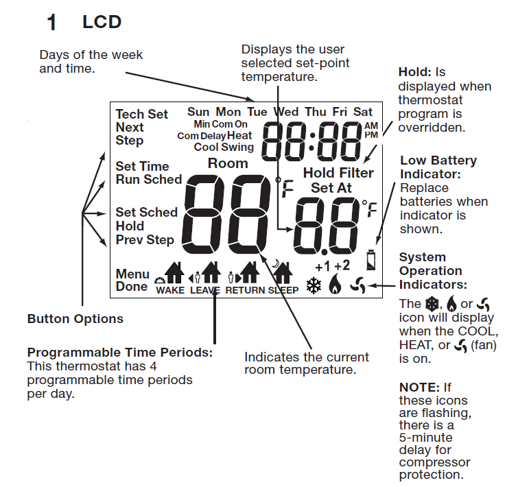
- LCD Screen
- Fan Switch
- System Switch
- Temperature Set-Point Buttons
- User Buttons
- Easy Change Battery Door
WALLPLATE INSTALLATION
Caution:
Electrical Hazard
Disconnect power before installing this product. Failure to do so can cause electric shock or equipment damage.
Mercury Notice:
This product is mercury-free. However, if this product is replacing a control that contains mercury, it needs to be disposed of properly. Contact your local waste management authority for instructions regarding recycling and proper disposal of the control.
WIRING
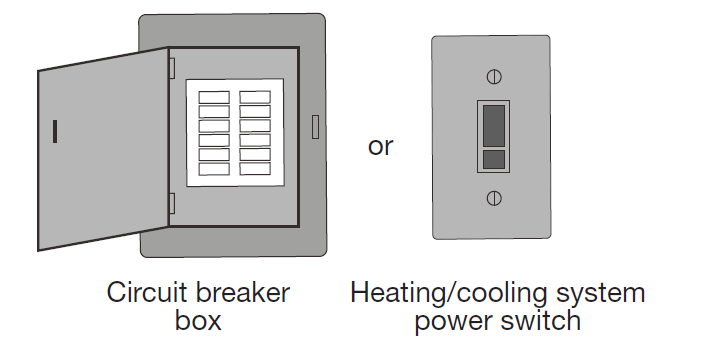
- Turn Off Power to the Heating/Cooling System
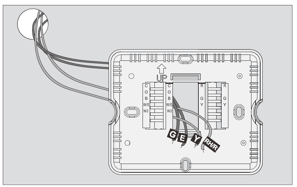
- Remove Old Thermostat
Remove the old thermostat but leave the wallplate with wires attached. Do not remove the wallplate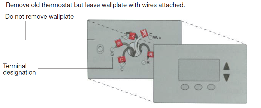
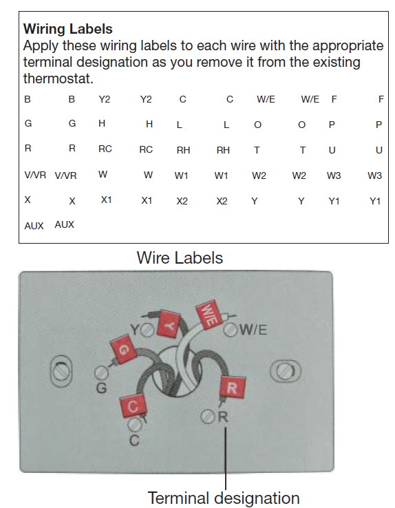
- Label Wires with Tags Label the wires using the supplied wire labels as you disconnect them.
- Separate Wallplate from New Thermostat
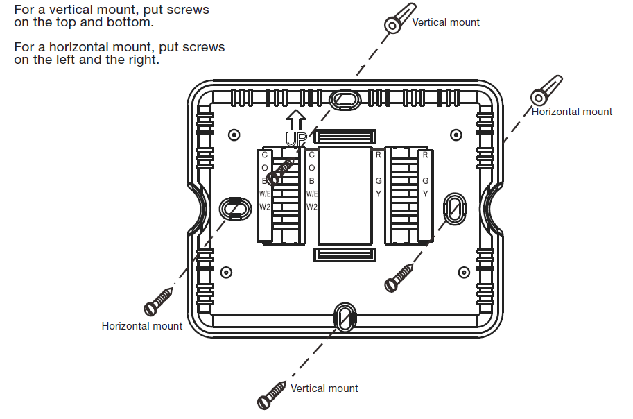
Remove the wallplate from the new thermostat and mount it onto the wall.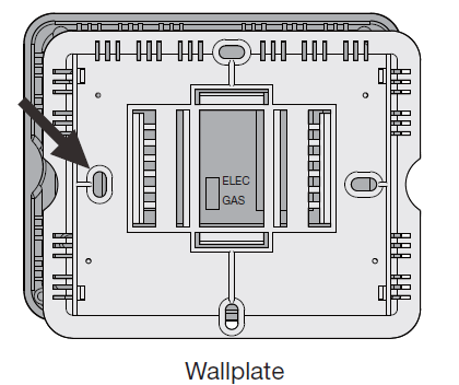
- Mount Wallplate for New Thermostat Mount the new wallplate using the included screws and anchors.
- Drill 3/16-in. holes for drywall
- Drill 3/16-in. holes for plaster
- Connect Wires Simply match wire labels.
If labels do not match the letters on the thermostat, check “Alternate Wiring (Conventional Systems) on page 9 and connect to the terminal as shown (see notes, below).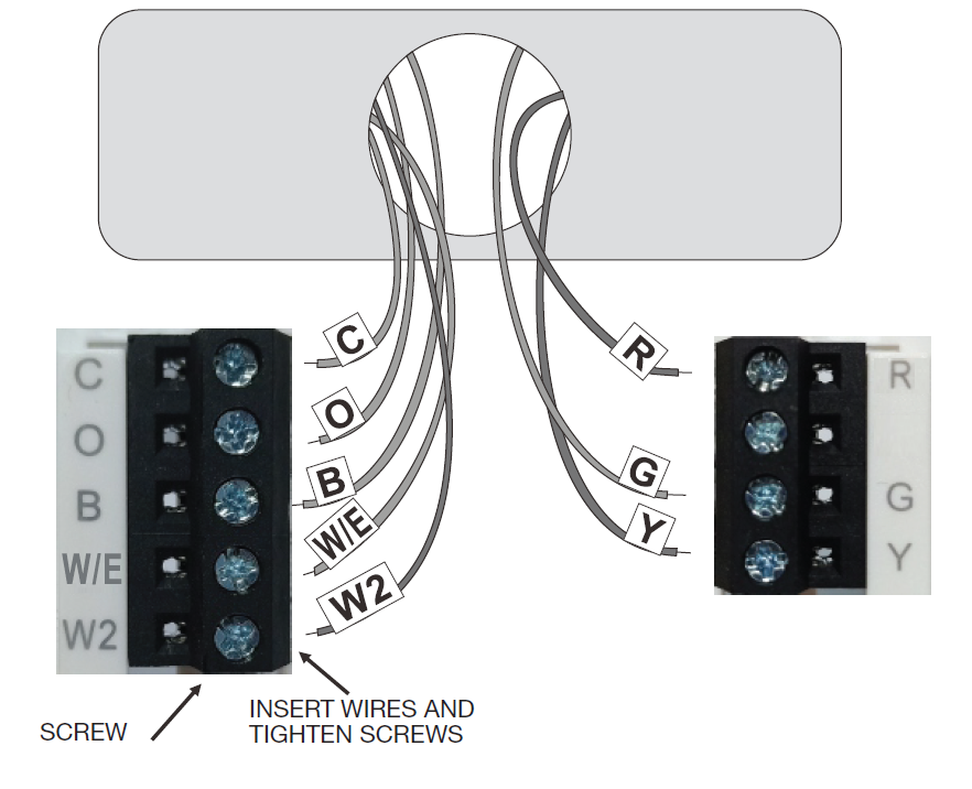
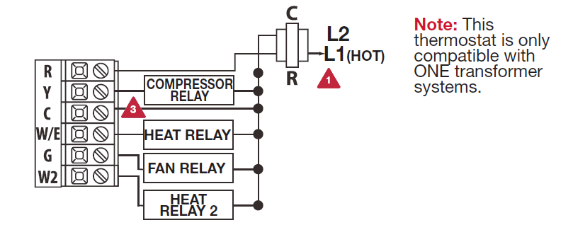
Alternate Wiring (Conventional Systems)
If labels do not match the letters on the thermostat, check the chart below and connect to the terminal as shown here (See notes, below).
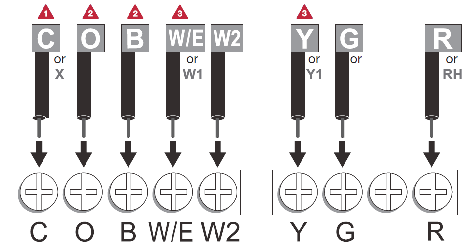
- If there is a C or X wire available then you can connect with C terminal. If there is no C or X wire then no need to connect with C terminal.
- If you have a heat pump without auxiliary/backup heat connect either the O or B, not both. If you do not have a heat pump, do not connect O or B. Wrap bare end of wire with electrical tape.
- Place a jumper (a piece of wire) between Y and W if you are using a heat pump without auxiliary/backup heat.
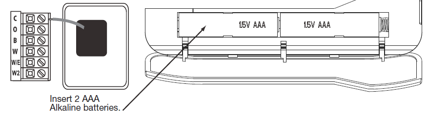
Terminal Designations
| Transformer Power | Transformer Power | |
| Transformer Common | Transformer Common | |
| Reversing Valve Energized in HEAT | Energized in HEAT | |
| Reversing Valve Energized in COOL | Energized in COOL | |
| Fan Relay | Fan Relay | |
| First Stage of Emergency HEAT | First Stage of HEAT | |
| Second Stage of HEAT/ EMERGENCY HEAT | Second Stage of HEAT | |
| First Stage of HEAT and COOL | First Stage of COOL |
Installation Tip
Do not overtighten terminal block screws, as this can damage the terminal block. A damaged terminal block can keep the thermostat from fitting on the sub-base correctly or cause system operation issues. Max Torque = 6in/Ibs.
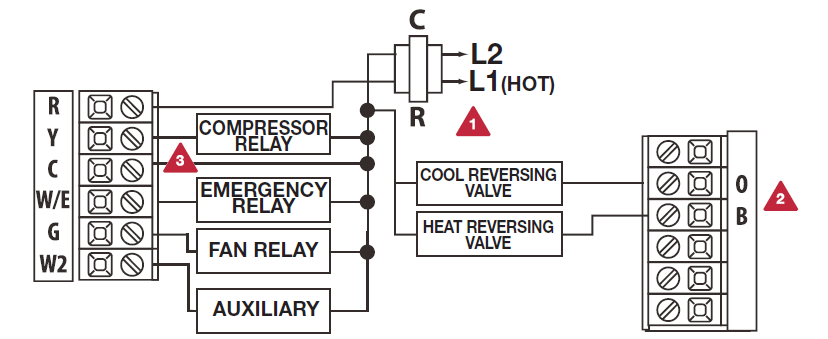
- Power supply.
- Use either O or B terminals for reversing the valve.
- Optional 24 VAC common connection when the thermostat is used in battery power mode.
- Jumper (not supplied).
2H/1C Heat Pump System

Typical 2H/1C Heat Pump System with separate emergency heat
Conventional System 1H/1C, 2H/1C (Heat pump set to OFF in tech settings)
This thermostat has an installer setup menu for easy configuration. Follow the procedure below to set up the thermostat to match the specific heating/cooling system.
- Press MENU.
- Press and hold TECH SET for 3 seconds.
- Configure the installer options as desired using the table on page 14.
Use ![]() or
or ![]() change settings and NEW STEP or PREV STEP to move from one option to another. Note: Only press DONE when you want to exit the Installer Setup options.
change settings and NEW STEP or PREV STEP to move from one option to another. Note: Only press DONE when you want to exit the Installer Setup options.

MOUNTING & BATTERY INSTALLATION
Align the 4 tabs on the faceplate with the corresponding slots on the back of the thermostat, then push gently until the thermostat snaps into place. Battery installation is optional if used with AC power (the C terminal is connected). During power outages, the batteries will save settings and power the display.
PROGRAMMING
- Press MENU.
- Press SET TIME.
- The day of the week will be flashing. Use
 or
or  to select the current day of the week.
 - Press NEXT STEP.
- The current hour will be flashing. Use or to select the current hour.
Note the correct a.m. or p.m. indicator is selected. - Press NEXT STEP.
- The minutes will be flashing. Use or to select the current minutes.
- Press DONE when completed.
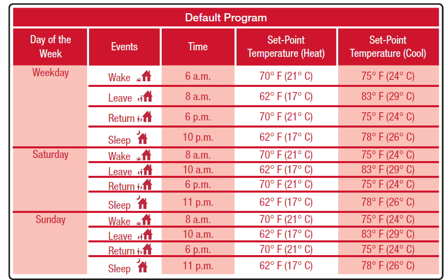
Default Program
This thermostat is pre-programmed for energy-saving operation. The default program is below:
You can use the table below to plan your customized program schedule.
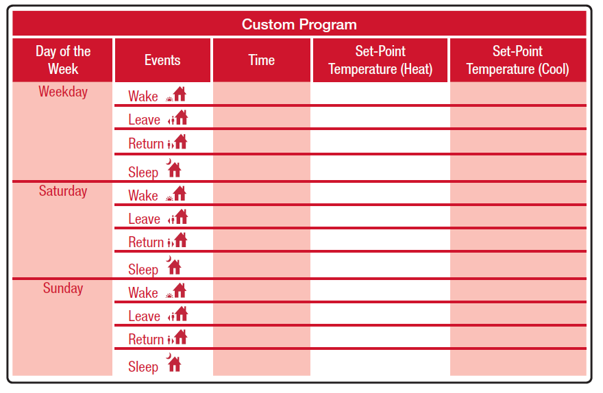
Custom Programming
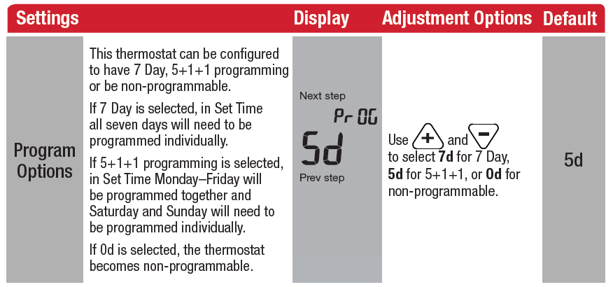
This thermostat can be configured to have 7-Day or 5+1+1 programming. If 7 Day is selected, all seven days will need to be programmed individually. If 5+1+1 programming is selected, Monday–Friday will be programmed together and Saturday and Sunday will need to be programmed individually. There are four time periods for each day (WAKE, LEAVE, RETURN, SLEEP).
Follow the steps below to customize your program schedule:
- Select HEAT or COOL. Note: Heat and cool need to be programmed separately.
- Press MENU (If the menu does not appear first, press RUN SCHED).
- Press SET SCHED. Note: Monday–Friday (or Monday if in 7-Day mode) will be displayed and the WAKE icon is shown.
- Time will be flashing. Use or to make your time selection for the WAKE time period for Monday–Friday (or Monday if in 7-Day mode).
- Press NEXT STEP.
- The set-point temperature will be flashing.
Useor to make your set-point selection for the WAKE time period for Monday–Friday (or Monday if in 7-Day mode). - Press NEXT STEP.
- Repeat steps 4 through 7 for the LEAVE time period, for the RETURN time period, and for the SLEEP time period for Monday–Friday (or Monday if in 7-Day mode).
- Repeat steps 4 through 8 for the Saturday WAKE, LEAVE, RETURN, and SLEEP time periods, and then again for the Sunday WAKE, LEAVE, RETURN, and SLEEP time periods for the 5+1+1 program schedule, and for each day for the 7-day program schedule.
Specifications
- Temperature Display Range…………………….41°F to 95°F (5°C to 35°C)
- Temperature Control Range…………………….44°F to 90°F (7°C to 32°C)
- Load Rating…………………………………………..1 amp per terminal, 1.5 amp maximum all terminals combined
- Display Accuracy…………………………………..± 1°F
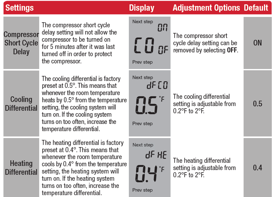
- Differential……………………………………………. Heating is adjustable from 0.2°F to 2.0°F
- Cooling is adjustable from 0.2°F to 2.0°F
- Power Source………………………………………. 18 to 30 VAC, NEC Class II, 50/60 Hz for hardwire (common wire) Battery power from 2 AAA Alkaline batteries
- Operating Ambient Temperature……………..32°F to +105°F (0°C to +41°C)
- Operating Humidity………………………………..90% non-condensing maximum
- Dimensions…………………………………………..4.72”W x 3.86”H x 0.98”D
Customer Service +1.800.304.6563
Technical Service +1.800.445.8299
[email protected]
www.robertshaw.com • 352-00301-001352-00304-0016 Rev. B
© 2021 Robertshaw Controls Company.
Robertshaw® is a trademark of Robertshaw Controls Company.
Reference
Download Manual:
Robertshaw RS9210 Programmable Thermostat Installation Manual
OTHER MANUALS
Robertshaw RS9210 Programmable Thermostat Operational Mnaual
Robertshaw RS9210 Programmable Thermostat Product Specifications Guide
![]()
Robertshaw RS9210 Programmable Thermostat Installation Manual
Leave a Reply