
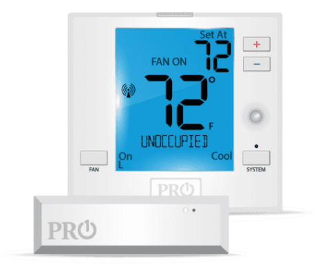
Pro1 Technologies T731WO Wireless Non-Programmable Thermostat
Pro1 Technologies
P.O. Box 3377
Springfield, MO 65808-3377 Toll-Free: 888-776-1427
Web: www.pro1iaq.com
Hours of Operation: M-F 9 AM – 6 PM Eastern
Thermostat Application Guide
| Description | |
| Gas or Oil Heat | Yes |
| Electric Furnace | Yes |
| Heat Pump (No Aux. or Emergency Heat) | Yes |
| Heat Pump (With Electric Aux.) | Yes |
| Heat Pump (With Gas Aux.) | No |
| Multi-Stage Systems | Yes |
| Heat Only Systems – Floor or Wall Furnace | Yes |
| Cool Only Systems | Yes |
| High, Medium and Low Fan Speed | Yes |
| Millivolt | No |
| Emergency Heat | No |
| Conventional Single Stage Furnace | Yes |
| Geothermal | Yes |
Power Type
- Battery Power
- Hardwire (Common Wire)
- Hardwire (Common Wire) with Battery
- Backup
A trained, experienced technician must install this product. Carefully read these instructions. You could damage this product or cause a hazardous condition if you fail to follow these instructions.
Installation Tips
Wall Locations
The thermostat should be installed approximately 4 to 5 feet above the floor. Select an area with average temperature and good air circulation.
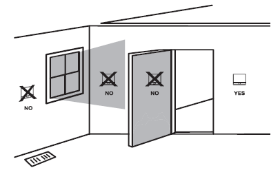
Pick an installation location that is easy for the user to access. The temperature of the location should be representative of the building.
Subbase Installation
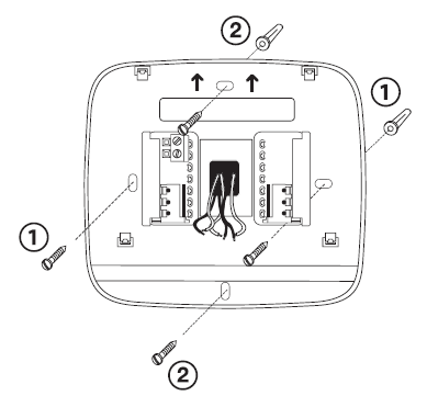
- Horizontal Mount V
- vertical Mount
For vertical mount put one screw on the top and one screw on the bottom. For horizontal mount put one screw on the left and one screw on the right.
Do not install thermostats in locations:
- Close to hot or cold air ducts
- That is in direct sunlight
- With an outside wall behind the thermostat
- In areas that do not require conditioning
- Where there are dead spots or drafts (in corners or behind doors) Where there might be concealed chimneys or pipes
Installation Tip:
Electrical Hazard
Failure to disconnect the power before beginning to install this product can cause electrical shock or equipment damage.
Mercury Notice
All of our products are mercury-free. However, if the product you are replacing contains mercury, dispose of it properly. Your local waste management authority can give you instructions on recycling and proper disposal.
Thermostat Quick Reference
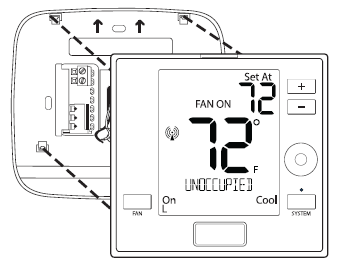
Mount Thermostat
Align the 4 tabs on the subbase with corresponding slots on the back of the thermostat, then push gently until the thermostat snaps in place.
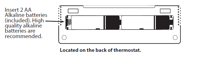
Battery Installation
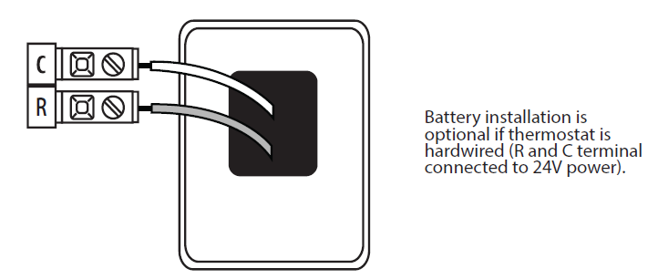
Important:
High-quality alkaline batteries are recommended. Rechargeable batteries or low-quality batteries do not guarantee a 1-year life span.
Getting to know your thermostat

- LCD
- Glow in the Dark Light Button Setpoint Buttons
- Fan Button
- System Button
- Occupancy Sensor
- (Occupancy Model Only)
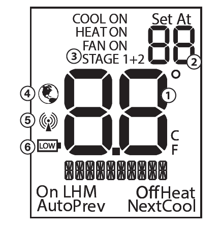
- Ambient Temperature:
Displays the current room temperature - Set At Temperature:
Displays the selected desired room temperature. - Staging Indicators:
If these or the fan indicators are flashing, it means that the system is in a delay of some type (compressor relay, cooling fan relay, or staging delay) or a pending change. - Energy Efficient Globe:
Indicates you are making an energy-efficient set at temperature. - Wireless Symbol: Indicates you have a wireless connection.
- Low Battery Indicator: Replace batteries when this indicator appears.
Important
The low battery indicator is displayed when the AA battery power is low. If the user fails to replace the battery within 21 days, the screen will only show the low battery indicator but maintain all functionality. If the user fails to replace the batteries after an additional 21 days (days 22-42 since the first “low battery” display) the setpoints will change to 55˚F (Heating) and 85˚F (Cooling). If the user adjusts the setpoint away from either of these, it will hold for 4 hours and then return to either 55˚F or 85˚F. After day 63 the batteries must be replaced immediately to avoid freezing or overheating because the thermostat will shut the unit off until the batteries are changed.
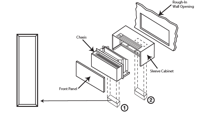
Base Module Mounting Tips
The range between the thermostat and the base module is up to 100 feet with no obstructions and up to 50 feet through standard building materials. To optimize the range try placing the base module with no metal between it and the thermostat. The base module is designed to be mounted behind the front grille of a packaged terminal air conditioner (PTAC). Refer to the PTAC manufacturer’s manual for instructions to remove the front grille. Check clearance to ensure the fit of the front grille after base module installation. See below for a few location recommendations.
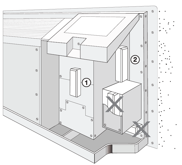
- Front Mount: Inside PTAC Housing
- Side Mount: Inside PTAC Housing
Wiring
Base Module Mounting Tips
When Working With A Vertical Unit
- Do not mount the Module inside the cabinet of the unit, or in a metal enclosure.
- Mount on the outside of the unit to maximize wireless communication.
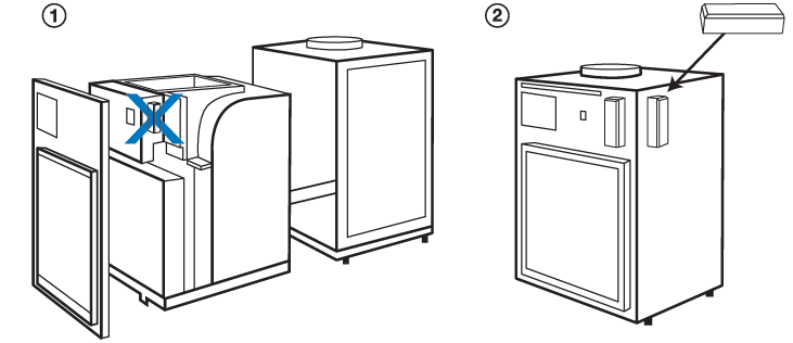
When Working With A Metal Sleeve Cabinet, Room Cabinet, or PTAC Cover
- If the cabinet has an open bottom, mount the module just inside the cabinet as close to the open bottom as possible without placing it in danger of being bumped or touched by furnishings, vacuum, etc.
- Another good module location would be on the underside of the top of the cabinet or cover. Directly behind the open Louver/Grill.
Caution: Electrical Hazard
Failure to disconnect the power before beginning to install this product can cause electrical shock or equipment damage.
Wiring
- If you are replacing a thermostat, make note of the terminal connections on the thermostat that is being replaced. In some cases, the wiring connections will not be color coded. For example, the green wire may not be connected to the G terminal.
- Loosen the terminal block screws. Insert wires then retighten terminal block screws.
- Place non-flammable insulation into the wall opening to prevent drafts.
All components of the control system and the thermostat installation must conform to Class II circuits per the NEC Code. Do not overtighten terminal block screws, as this can damage the terminal block. A damaged terminal block can keep the thermostat from fitting on the sub base correctly or cause system operation issues. Max Torque = 6in-lbs.
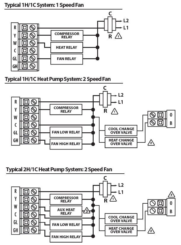
Terminal Designations
| R | Transformer Power | Transformer Power |
| C | Transformer Common | Transformer Common |
| B | Changeover Valve Energized in HEAT | N/A |
| O | Changeover Valve Energized in COOL | N/A |
| GL | Fan Relay, Low | Fan Relay, Low |
| GH | Fan Relay, High | Fan Relay, High |
| W | Second Stage of HEAT | First Stage of HEAT |
| Y | First Stage of HEAT and COOL | First Stage of COOL |
The base module is packaged with labeled thermostat wire. Wire appropriately into the PTAC board terminals. The thermostat and Base Module come factory linked (communicating) out of the box. However, if the link is lost, use the process on page 14 to re-link the devices.
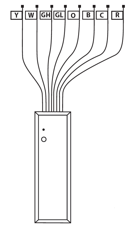
The base module may be mounted using adhesive tapes, such as double-sided tape or hook and loop strips. The base module must be hardwired (C & R terminals connected to 24V power). Use a secondary source of securement to prevent the module from dropping into the condenser drain pan.
Connecting to a PTAC
When connecting the Base Module to a PTAC, refer to the PTAC manufacturer’s instructions to enable remote thermostat operation.
Caution
Electrical Hazard Failure to disconnect the power before beginning to install this product can cause electrical shock or equipment damage.
Warning
All components of the control system and the thermostat installation must conform to Class II circuits per the NEC Code.
Thermostat Wiring Tips
C Terminal
The C (common wire) terminal does not have to be connected when the thermostat is powered by batteries.
Wire Specifications
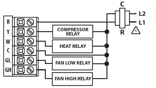
Use shielded or non-shielded 18-22 gauge thermostat wire. Most PTAC systems support two-speed fan operation. In a single-speed fan PTAC system or conventional single-speed fan system, the GL terminal will be used, and “I” must be selected in the Technician Setup Menu.
- Power supply
- The thermostat must be set to O or B to match the changeover valve, O is the cool changeover valve, and B is the heat changeover valve.
- The Aux. Heat Relay is energized as the second stage of heat.
Typical 1H/1C System: 2-Speed Fan
Technician Setup
- To enter Tech Setup Menu, press
 and
and  hold together for 3 seconds.
 - Use or to select the desired valve for each setting.
- Tap the previous or next to select different tech settings.
- To exit Tech Setup Menu, press and hold together for 3 seconds or wait 60 seconds
Important Tech Setting Notes
- Tech settings must be transferred to the base module.
- The transfer happens automatically when you exit the tech menu.
| Tech Setup Steps | LCD Will Show | Adjustment Options | Default | |
| Room Temperature Calibration | This feature allows the installer to change the calibration of the am- bient room temperature display. For example, if the thermostat reads 70 degrees and you would like it to read 72 then select +2. | 0
CALIBRATE |
4 ˚ – -4 ˚ | 0˚F |
|
Cooling Swing |
The swing setting, often called “cycle rate”, “differential” or “antic- ipation” is adjustable and dictates how frequenlty the system cycles on and off. For example: A swing setting of 0.8˚ will turn the cooling on at approximately 0.8˚ above the setpoint and turn the cooling off at approximately 0.8˚ below the setpoint. |
0.8 COOL SWING |
0.2 ˚ – 2 ˚ |
0.8˚ |
|
Heating Swing |
The swing setting, often called “cycle rate”, “differential” or “antic- ipation” is adjustable and dictates how frequenlty the system cycles on and off. For example: A swing setting of 0.8˚ will turn the heating on at approximately 0.8˚ below the setpoint and turn the heating off at approximately 0.5˚ above the setpoint. |
0.8 HEAT SWING |
0.2 ˚ – 2 ˚ |
0.8˚ |
| Tech Setup Steps | LCD Will Show | Adjustment Options | Default | |
|
Fan Operation |
Select Gas (GS) for applications where the air handlers controls the fan during a call for heat. Slect Electric (EL) if you would like the thermostat to control the fan during a call for heat. | EL
FAN SET |
EL = Electric for thermostat control
GS = Gas for system control |
Electric |
|
Fan Speeds |
Select number of fan stages you would like the thermostat to operate. | 2
FAN SPEEDS |
1 = 1 Speed: On, Auto
2 = 2 Speed: Low (On L), High (On H), Auto 3 = 3 Speed: Low (On L), Med (On M), High (On H), Auto |
2 Speed:
Low High Auto |
| Medium | Select the terminal you would like to use to operate the medium speed fan. (only if fan speed is set to 3) | 0
M FAN TERM |
O or B | O |
| Speed Fan | ||||
| Terminal | ||||
| Designation | ||||
|
F or C |
Select F for Fahenheit temperature or C for Celsius. |
F OR C |
F = Fahrenheit C = Celsius | F |
|
Display Light |
The display light can be configured to stay on permanently or only when a key is pressed.
NOTE: HARDWIRE ONLY. Keeping the display light continually “ON” will greatly reduce battery life. |
OF
dL DISP LIGHT |
OF = OFF configures the display light to come on when the light key or any button is pressed.
LO = LOW configures the display light to stay on at a lower intensity until a button is pressed and then it goes to the normal high intensity.
HI = HIGH configures the dis- play light to stay on at normal high intensity all the time. |
OFF when battery powered / LOW when hardwired |
|
Heat Pump |
When turned on the thermostat will operate a heat pump. Y will be the first stage of heat & cool, W will be the second stage of heat. | OF
HEAT PUMP |
OFF configures the thermostat for non heat pump systems. ON configures the thermostat for heat pump systems. |
OFF |
| Tech Setup Steps | LCD Will Show | Adjustment Options Default | |||||
|
Compressor Short Cycle |
This setting protects the compressor from “short cycling”. When ON, the compressor will delay for 5 minutes after it was last turned off. |
COMP DELAY |
ON = Turns 5 minute delay on OF(OFF) = Removes the delay | ON | |||
| Heating Temperature Setpoint Limit | Set a maximum heat setpoint value. Once set, the setpoint temperature cannot be raised above this value. | 90
HE HEAT LIMIT |
45.0 – 90.0˚ F
7.0 – 32.0˚ C |
90˚ | |||
| Cooling Temperature Setpoint Limit | Set a minimum cool setpoint valve. Once set, the setpoint temperature cannot be lowered below this value. | 44
44 COOL LIMIT |
45.0 – 90.0˚ F
7.0 – 32.0˚ C |
44˚ | |||
|
Enter Network (Only displayed if you are not paired) |
This setting is a secondary way to pair the thermostat with the base module. | P
START PAIR |
Press the “+” button to enter paring mode | N/A | |||
|
Exit Network (Only displayed if you are not paired) |
Exit network (only displayed if you are paired). | UP
UNPAIR |
Press the “+” button to exit the network | N/A | |||
| Signal Strength
(Only shows if you are paired) |
View the strength of the wireless signal. 1 indicates a weak signal and 5 indicates a strong signal. | 3
SIG STR |
1-5 | N/A | |||
| Tech Setup Steps LCDWill Show | Adjustment Options Default | |||||
|
Local Occupancy Sensor |
When using the Occupancy model the installer can choose to utilize the occupancy sensor to set back the room temperature while it is not being occupied. | 0F
OCC SENSOR |
ON OF(OFF) | OF | ||
| Duration of Occupancy
(Only displayed if Local Occupancy Sensor is ON) |
When the occupancy sensor is turned on you have the ability to set how long the thermostat will go into occupancy mode everytime a person is sensed. | 8
OCC LENGTH |
30 = 30 minutes, 1 = 1 hour,
2 = 2 hours, 3 = 3 hours, 4 = 4 hours, 5 = 5 hours, 6 = 6 hours, 7 = 7 hours, 8 =8 hours, 9 = 9 hours, 10 = 10 hours, 11 = 11 hours, and 12 = 12 hours. |
8 |
||
| Occupied Cool Setting
(Only displayed if Local Occupancy Sensor is ON) |
Set the cooling temperature and fan operation that you would like the system to be while the space is being occupied. | 75
OCC COOL |
Full temperature range defined by setpoint limits.
First adjust the temperature using the + and – buttons. Use the Fan button to change the fan operation. |
78˚ |
||
| Occupied Heat Setting
(Only displayed if Local Occupancy Sensor is ON) |
Set the heating temperature and fan operation that you would like the system to be while the space is being occupied. | 70
OCC HEAT |
Full temperature range defined by setpoint limits.
First adjust the temperature using the + and – buttons. Use the Fan button to change the fan operation. |
70˚ |
||
|
Unoccupied Cool Setting (Only displayed if Local Occupancy Sensor is ON) |
Set the cool temperature and fan operation that you would like the system to be while the space is unoccupied. | 83
UNOCC HEAT |
Full temperature range defined by setpoint limits.
First adjust the temperature using the + and – buttons. Use the Fan button to change the fan operation. normal high intensity all the time. |
83˚ |
||
| Tech Setup Steps LCDWill Show | Adjustment Options Default | |||||
| Unoccupied Heat Setting
(Only displayed if Local Occupancy Sensor is ON) |
Set the heat temperature and fan operation that you would like the system to be while the space is unoccupied. | 62
UNOCC COOL |
Full temperature range defined by setpoint limits.
First adjust the temperature using the + and – buttons. Use the Fan button to change the fan operation. |
62˚ |
||
|
Occupancy Sensitivity Setting (Only displayed if Local Occupancy Sensor is ON) |
Set the level of sensitivity of the occupancy sensor. Lowering the sensitivity will cause the sensor to respond only to larger movements. |
HI |
High Sensitivity:
This is the most sensitive setting and will detect very slight motions. This is the recommended setting because it will work well for nearly all applications, and will detect any movement. Medium Sensitivity: This is the medium sensitive setting and can be used without pets setting it off. Low Sensitivity: This is the least sensitive setting and can be used in areas of heavy traffic. This will not be set off by pets, small children, or people more than 20’ from the sensor location. |
HI |
||
|
Cycle Minimizer (Only displayed if local Occupancy Sensor is ON) |
Maximize efficiency and equipment longevity by increasing the heating and cooling swing settings to 2.0˚ during the unoccupied and leave time periods. This will result in significantly fewer system cycles. | 0F
CYCLE MIN |
ON OF(OFF) |
OF |
||
Establishing A Connection
Establishing Communication between the thermostat & the base module The Thermostat and Base module in this package are linked at our factory. Upon powering up they will automatically begin communicating. If you wish to make any changes to the network such as adding or removing devices, please follow the instructions on this page.
Establishing A Connection
On the Base module:
- Press the button next to the LED.
- The Base module will begin double blinking pink for 2 minutes while it waits for a remote to join.
- Once a device joins, the LED will show green blinks and return to normal operating mode.
How To Pair
On the Thermostat:
- Press and hold the light button for 3 seconds. The LED will flash 3 times and pair with the base module.
- The Thermostat will attempt to connect to a Base module within the range
- Once paired, the LCD will temporarily display “PAIRED” when it joins with a Base module.
How To Unpair
On the Base Module:
- PRESS and HOLD the button next to the LED for 6 seconds.
- The Base module LED will turn RED for 6 seconds.
- All connected devices will be deleted.
On the Thermostat
- Enter the “UNPAIRING” tech menu.
- Press and hold the “+” button.
- The LCD will show “UNPAIRED”.
- The Thermostat will no longer be connected to a network.
Base Module LED Information
The Base module’s LED is used to communicate the status of the wireless network.
- Green Blink at 3s: Normal operating mode. All devices are connected and healthy.
- Yellow Blink at 3s: Normal operating mode. One or more (but not all) remote devices are NOT reporting.
- Red Blink at 3s: Normal operating mode. ALL network devices are NOT reporting.
- White Blink at 3s: Unpaired mode. The base module is powered but is NOT paired to any remotes.
- Blue double blink: Transmission received from a remote.
- Purple double blink: The base module is in pairing mode waiting for a remote.
- Green 5 quick blinks: A remote has successfully been added to the base modules network.
Note:
This equipment has been tested and found to comply with the limits for a Class B digital device, pursuant to part 15 of the FCC Rules. These limits are designed to provide reasonable protection against harmful interference in a residential installation. This equipment generates, uses and can radiate radio frequency energy and, if not installed and used in accordance with the instructions, may cause harmful interference to radio communications. However, there is no guarantee that interference will not occur in a particular installation. If this equipment does cause harmful interference to radio or television reception, which can be determined by turning the equipment off and on, the user is encouraged to try to correct the interference by one or more of the following measures:
- Reorient or relocate the receiving antenna.
- Increase the separation between the equipment and the receiver.
- Connect the equipment to an outlet on a circuit different from that to which the receiver is connected.
- Consult the dealer or an experienced radio/TV technician for help.
Network Specifications
Wireless Network Specifications
- The thermostat will attempt to pair with the first Base module it “hears”. Do not attempt to create more than one “pair” at the same time in the same
- To ensure paring success, place the T731W/O within a few feet of the Base module Once paired, the signal strength tech menu can be used to ensure a robust wireless connection.
- Placing either device in or around large metal objects can severely degrade the wireless
- The wireless network will automatically recover in the event of a power loss or temporary signal
Network Capabilities
- Thermostat units will require up to 60 seconds to reflect changes in the system.
Specifications Thermostat
- The display range of temperature … 41˚F to 95˚F (5˚C to 35˚C) The control range of temperature 44˚F to 90˚F (7˚C to 32˚C)
- Load rating…………………… 1 amp per terminal, 1.5 amp
- maximum all terminals combined Swing (cycle rate or differential) Heating is adjustable from 0.2˚ to 2.0˚
- Cooling is adjustable from 0.2˚ to 2.0˚ Power source 18 to 30 VAC, NEC Class II, 50/60 Hz for hardwire
- Battery power from 2 AA Alkaline batteries
- Operating ambient……………. 32˚F to +105˚F (0˚C to +41˚C)
- Operating humidity……………. 90% non-condensing maximum
- Dimensions of thermostat……….. 4.7”W x 4.4”H x 1.1”D
- Frequency…………………… 916 MHz
Base Module
- Load rating…………………… 1 amp per terminal, 1.5 amp
- maximum all terminals combined. Power source 18 to 30 VAC, NEC Class II, 50/60 Hz
- Operating ambient……………. 32˚F to +150˚F (0˚C to +65˚C)
- Operating humidity……………. 90% non-condensing maximum
Note
Changes or modifications not expressly approved by the manufacturer could void the user’s authority to operate the equipment
Reference
Download Manual:
Pro1 Technologies T731WO Wireless Non-Programmable Thermostat Installational Manual
OTHER MANUALS
Pro1 Technologies T731WO Wireless Non-Programmable Thermostat Product Specifications Guide
Pro1 Technologies T731WO Wireless Non-Programmable Thermostat Operational Manual
![]()
Pro1 Technologies T731WO Wireless Non-Programmable Thermostat Installational Manual
Leave a Reply