
![]()
Pro1 Technologies T701 Programable Thermostats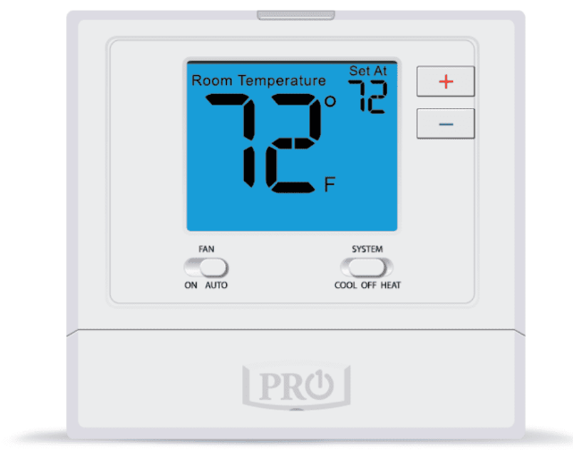
Pro1 Technologies
- P.O. Box 3377
- Springfield, MO 65808-3377 Toll-Free: 888-776-1427
- Web: www.pro1iaq.com
- Hours of Operation: M-F 9 AM – 6 PM Eastern
Thermostat Application Guide
| Description | |
| Gas or Oil Heat | Yes |
| Electric Furnace | Yes |
| Heat Pump (No Aux. or Emergency Heat) | Yes |
| Heat Pump (With Aux. or Emergency Heat) | Yes |
| Multi-Stage Systems | Yes |
| Heat Only Systems | Yes |
| Heat Only Systems – Floor or Wall Furnace | Yes |
| Cool Only Systems | Yes |
| Millivolt Conventional Systems | Yes |
| Two Transformer Systems | No |
Power Type
Hardwire (24V Common Wire)
Installation Tips
Wall Locations
The thermostat should be installed approximately 4 to 5 feet above the floor. Select an area with average temperature and good air circulation.

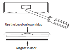
Removing The Private Label Badge
Gently slide a screwdriver into the bottom edge of the badge. Gently turn the screwdriver counterclockwise. The badge is held on by a magnet in the well of the battery door. The badge should pry off easily. DO NOT USE FORCE. All of our thermostats use the same universal magnetic badge. Visit the company website to learn more about our free private label program.
Subbase Installation

- Horizontal Mount
- Vertical Mount
Mount Thermostat
Align the 4 tabs on the subbase with corresponding slots on the back of the thermostat, then push gently until the thermostat snaps in place.

Getting to know your thermostat
- LCD
- Glow in the dark light button
- Fan button
- System button
- Easy change battery door
- Temperature setpoint buttons
Wiring
- Power Supply
- Factory-installed jumper, remove only when installing on a 2-installer system.
- Use either O or B terminals for changeover value.
- Use a small piece of wire (not included) to connect W and Y terminals.
- Set fan operation to electric
- A 24 VAC 500mA common connection is required with this thermostat.
Replacement Thermostat Wiring
- If you are replacing a thermostat, make note of the terminal connections on the thermostat that is being replaced. In some cases, the wiring connections will not be color coded. For example, the green wire may not be connected to the G terminal.
- Loosen the terminal block screws. Insert wires then retighten terminal block screws.
- Place non-flammable insulation into the wall opening to prevent drafts.
- This thermostat requires a 24V common wire to the C terminal.
Wiring Chart
For all systems, the following terminals are wired according to whether you have a single or dual transformer system as shown:
Technician Setup
To enter tech setup:
- Press and hold the + and – buttons for 3 seconds.
- Press the TECH button at the lower left.
- Configure the installer options as desired using the table below. Use the + or – buttons to change settings and the PREV and NEXT buttons to move from one step to another.
- To exit tech setup: press and hold the + and – buttons for 3 seconds, or wait 20 seconds.
Tech Setup continued
WIFI Setup
- Press and hold the + and – buttons for 3 seconds.
- Press the WIFI button at the lower right.
- The top of the display will show:
- “WIFI NOTOK” is NOT connected to WIFI. “WIFI OK” if connected to WIFI.
- IF the NEXT button is pressed, the top of the display will show:
- The firmware and software versions that are installed on the thermostat. You can scroll through them with the + and – buttons.
- IF the NEXT button is pressed again, the top of the display will show:
- The SSID # of the thermostat. if NEXT is pressed again, you will return to step 4.
- Go through steps 1 and 2 from the WIFI menu at left.
- Press and hold the TECH button at the lower left for 3 seconds.
- The top of the display will show:
- “RESET WIFI”
- Press the YES button at the lower left. After a 5-second countdown, the thermostat will reset.
- Or press NO to exit
REFERENCE
DOWNLOAD MANUAL
Pro1 Technologies T701 Programable Thermostats Installational Manual
OTHER MANUALS:
Pro1 Technologies T701 Programable Thermostats Operation Manual
![]()
Pro1 Technologies T701 Programable Thermostats Installational Manual
Leave a Reply