
PERRY 1TP TE402/B WALL MOUNTING ELECTRONIC DIGITAL THERMOSTAT
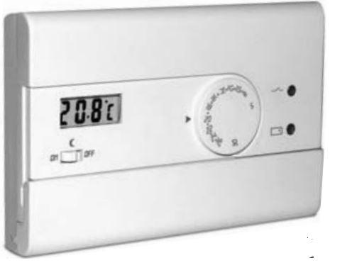
TECHNICAL DATA
- Supply voltage:N° 2 alkaline batteries 1,5V each type AAA (LR03)
- Type of action, disconnect and device:1/ B / Electronic
- Type of output: Relay with changeover contact NO / COM / NC voltage free – max 8(2)A / 250 V~
- Output connection (load):2 or 3 conductors
- Wire section at terminals: min. 0,75 mm ÷ max. 1,5 mm
- Insulation type:Class II
- Protection degree: IP30
- Pollution: Normal
- Operating temperature limits:0 °C ÷ +50 °C
- Storage temperature limits:-10 °C ÷ +65 °C
- Temperature adjustment range:+5 °C ÷ +30 °C
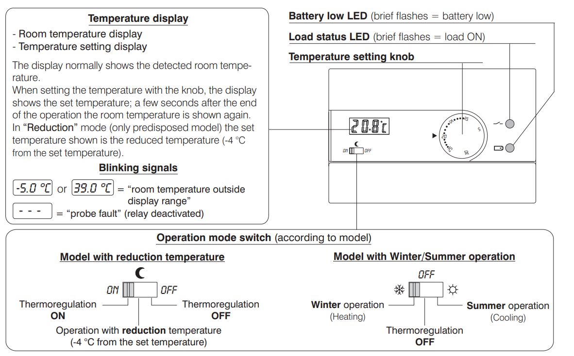
- Temperature display range:-5 °C ÷ +39 °C
- Reduction temperature:-4 °C from the set temperature (only for the predisposed model)
- The precision of reading of the temperature:± 0,5 °C
- Ambient temperature indicator resolution:0,1 °C
- Differential operation:t selectable: = 0,3 °C – 0,5 °C – 0,7 °C – 0,9 °C
- Thermal gradient:1 °K/15 min
- Battery life:1 year min.
- Time remaining from battery low indication: About 1 month
- Reference standard for CE mark: LVD EN60730-2-9
(directives 73/23/CEE – 89/336/CEE): EMC EN60730-2-9
SIGNALS AND CONTROLS
INSTALLATION GUIDELINES
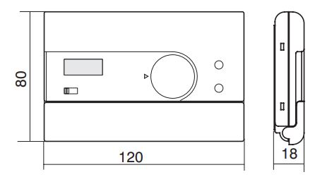
Dimensions
Important: installation and electrical connections of devices and appliances must be carried out by skilled people and in compliance with current regulations. The manufacturer declines any liability in connection with the use of products subject to special environmental and/or installation standards.
Installation of thermostat: independent-fixed
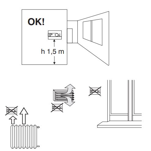
- Wall mounting.
- Install the thermostat at a height of 1,5 m ÷ 1,7 m from the floor, far from heat sources, air vents, doors or windows and anything else that could affect its operation.
FIXING BASE TO THE WALL
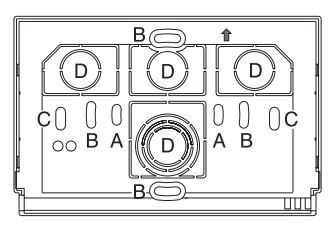
- Isolate the controlled appliance from the electrical power supply.
- Fix with screws the base of the thermostat to the back box (or to the wall), using the pairs of holes provided.
- for round box (diam. 60mm) with claws
- for round or square box (with screws)
- for 3 spaces rectangular box (with screws)
- knockouts allowing entry of wires (flexible only)
N. B.: To ensure the thermostat is fitted correctly to the wall-mounted base, care must be taken to ensure that the base is not distorted by screwing the back box too tightly to the wall.
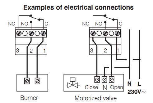
ELECTRICAL CONNECTIONS
- turn off the electrical power to the wiring.
- Connect the controlled device to the terminals:
- n° – common
- n° – normally open contact
- n° – normally closed contact
Note for the contractor
Make the electrical connections taking particular care in the event of surface mounting without box that the wires are correctly arranged and do not hinder a proper fit between the body and the base.
TEMPERATURE DIFFERENTIAL VALUE SETTING
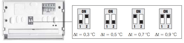
The thermostat operates in differential modes (ON-OFF) with a modifiable differential value (factory-set to 0,5 °C).
Changing the differential: position the dip-switches, located on the back of the thermostat, for the required differential value.
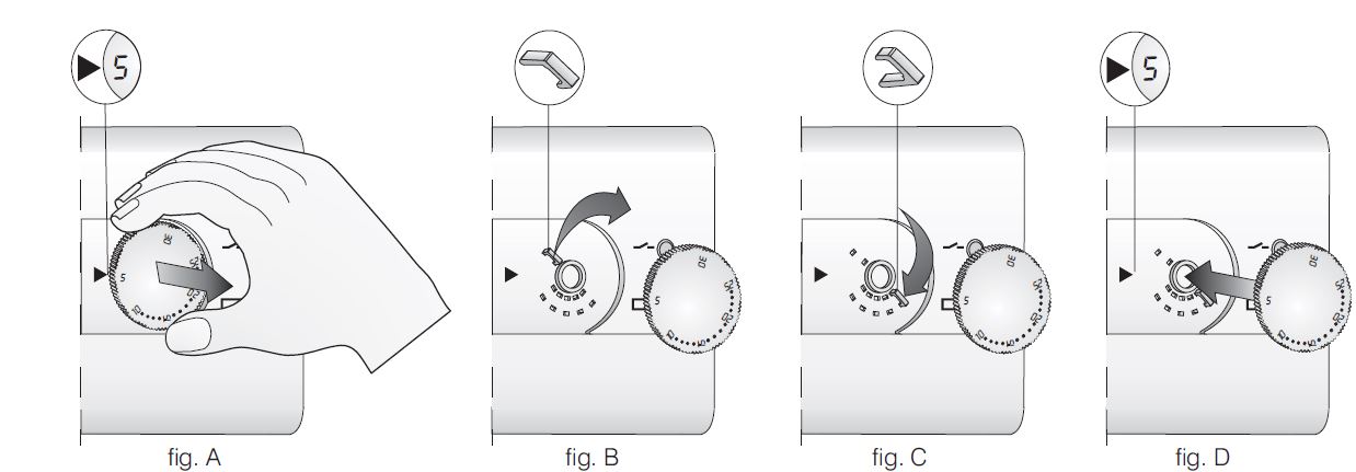
FIXING THE THERMOSTAT TO BASE
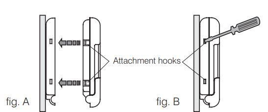
Fit the body to the base as shown in fig. A.
Exert light pressure until you hear the click of the attachment hooks.
To remove thermostat the insert a small screwdriver as a lever in the position corresponding to the attachment hooks (fig. B).
INSERTING OR REPLACING BATTERIES
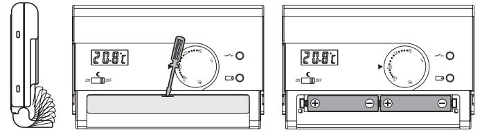
- Open the cover of the battery compartment.
- Replace the dead batteries with two 1,5 V type AAA (LR03) alkaline batteries, paying attention to their polarity.
- Close the cover.
LIMITATION OF THE MAXIMUM ROOM TEMPERATURE
The maximum adjustable value of the temperature setting can be limited as follows:
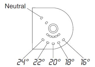
- turn the knob to the 5 °C mark; then remove the knob (fig. A)
- extract the JUMPER from its housing (fig. B)
- Insert the JUMPER in the holes corresponding to the desired temperature (fig. C) fig.
- replace the knob, making certain it is positioned as before the 5 °C position coinciding with the index on the front of the case (fig. D).
REFERENCE:
DOWNLOAD MANUALS:
PERRY 1TP TE402-B WALL MOUNTING ELECTRONIC DIGITAL THERMOSTAT USER INSTRUCTIONS

PERRY 1TP TE402/B WALL MOUNTING ELECTRONIC DIGITAL THERMOSTAT USER INSTRUCTIONS
Leave a Reply