
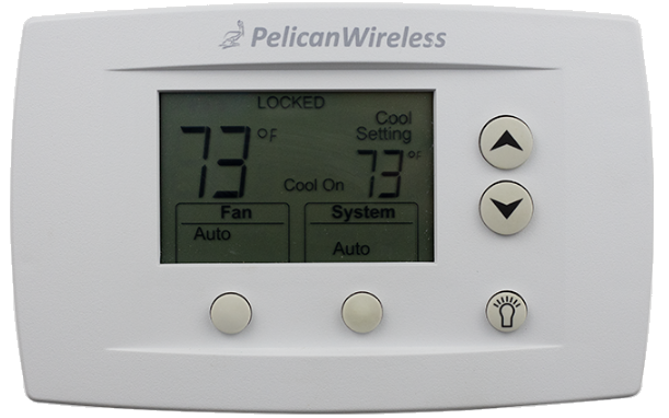
Pelican TS250 Programmable Thermostat
Before Removing the Old Thermostat!
Note the wire colors and letter designations of the existing thermostat to assist in identifying the correct wiring connections to the TS250.
CAUTION Failure to follow these instructions can damage the product or cause a hazardous condition. Disconnect power during the installation of this product. All wiring must conform to local codes and ordinances. We strongly recommend that any installation or servicing be performed by a qualified technician. This thermostat is designed for use with 24VAC systems only. For additional support contact Pelican Technical Support at 888-512-0490 or email [email protected].
WARNING NEVER INSTALL THE PELICAN THERMOSTAT ENCLOSED IN METAL. WIRELESS CANNOT COMMUNICATE THROUGH METAL.
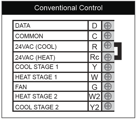
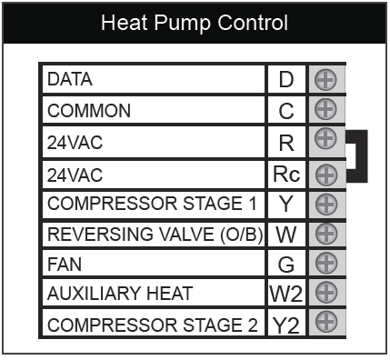
Thermostat Terminal Designations
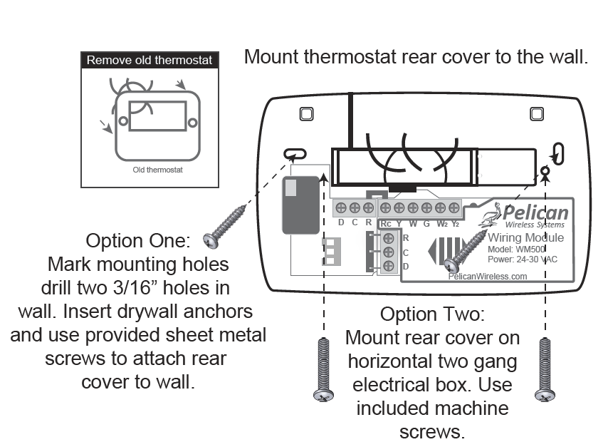
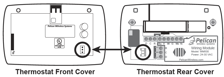
TS250 Mounting and Assembly
- Grasp front and back of thermostat and firmly pull apart.
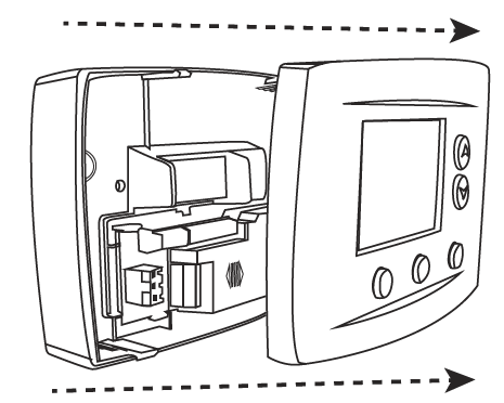
- Align three pin connector from thermostat front cover to three pin connector on rear cover. Push front cover onto rear cover until secure.
Optional Tamper Resistant Lock
The thermostat contains an internal locking mechanism to secure the front cover to the rear cover. This is intended to keep untrained individuals from tampering with the power and thermostat wire. To engage the lock, assemble the thermostat and insert a 7/64″ Allen wrench (not included) into the key hole on the top of the thermostat. Rotate clockwise until reaching the stop to secure. Rotate counter-clockwise until reaching the stop to release.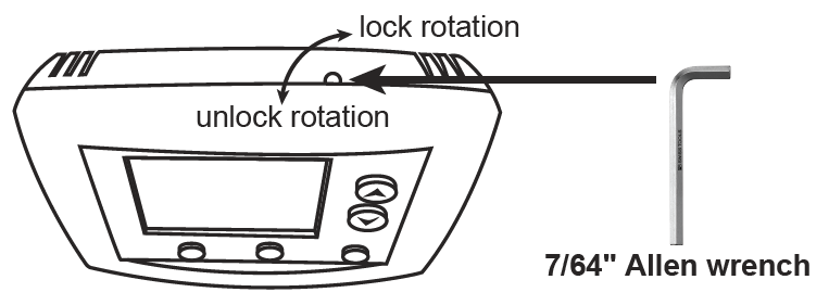
Wiring Guide
Conventional Wiring Guide
5 Wire, 24VAC Conventional 1 stage cooling with 1 stage heat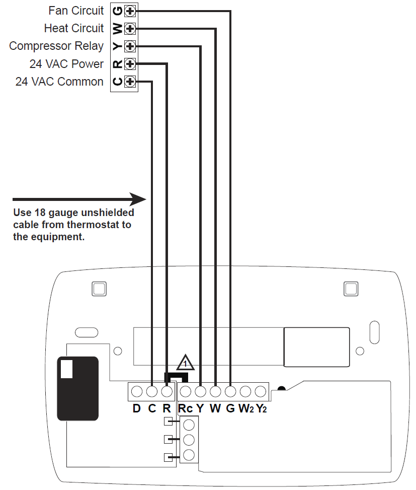
- For a Two Transformer System – remove jumper between R and Rc. Connect the 24VAC power for energizing the unit’s Compressor to thermostat’s (R) terminal. Connect second 24VAC power to thermostat’s (Rc) terminal.
6 Wire, 24VAC Conventional 1 stage cooling with 2 stage heat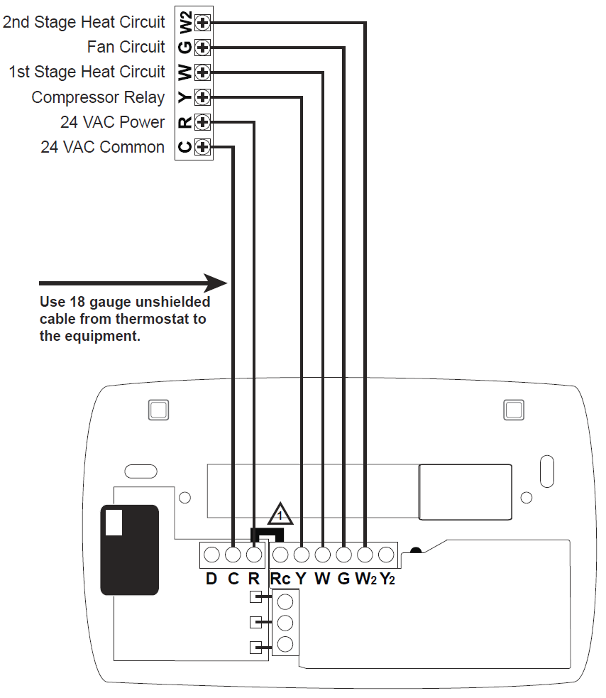
- For a Two Transformer System – remove jumper between R and Rc. Connect the 24VAC power for energizing the unit’s Compressor to thermostat’s (R) terminal. Connect second 24VAC power to thermostat’s (Rc) terminal.
6 Wire, 24VAC Conventional 2 stage cooling with 1 stage heat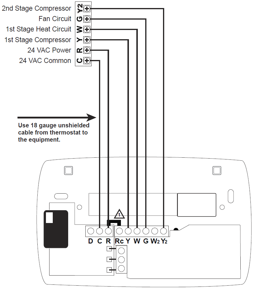
- For a Two Transformer System – remove jumper between R and Rc. Connect the 24VAC power for energizing the unit’s Compressor to thermostat’s (R) terminal. Connect second 24VAC power to thermostat’s (Rc) terminal.
7 Wire, 24VAC Conventional 2 stage cooling with 2 stage heat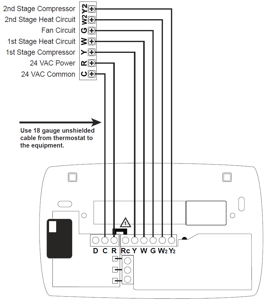
- For a Two Transformer System – remove jumper between R and Rc. Connect the 24VAC power for energizing the unit’s Compressor to thermostat’s (R) terminal. Connect second 24VAC power to thermostat’s (Rc) terminal.
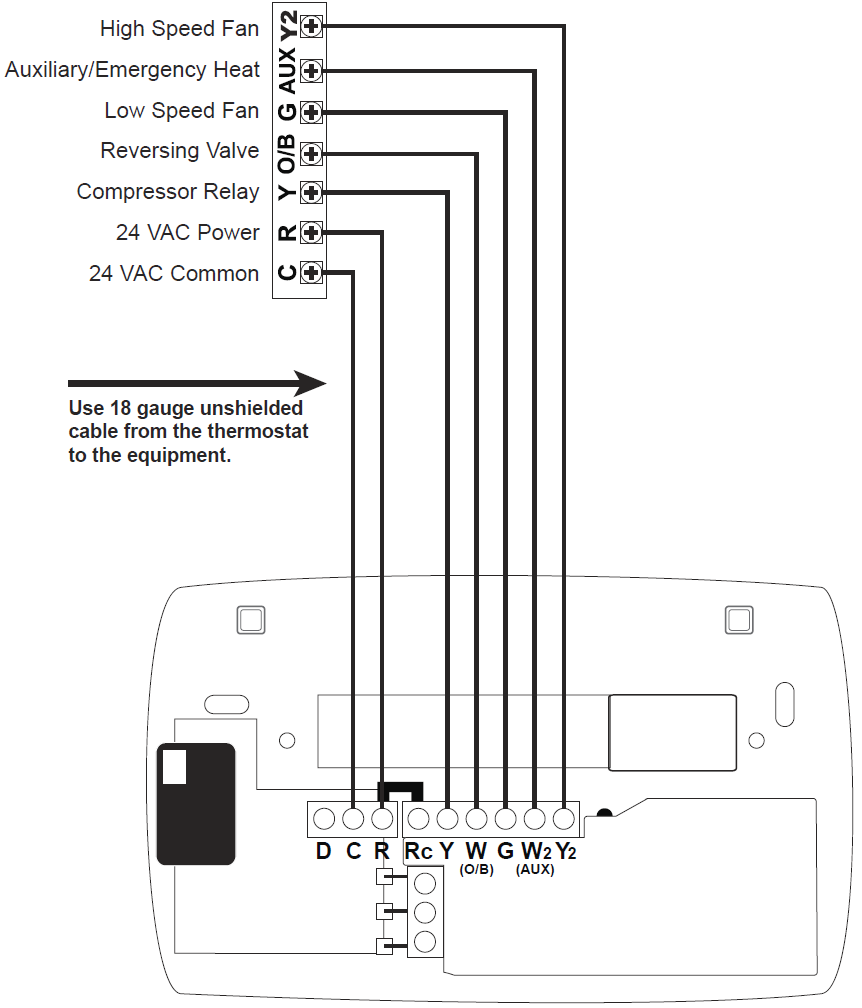
7 Wire, 24VAC Conventional 1 stage cooling, 2 stage heat, and 2 fan speeds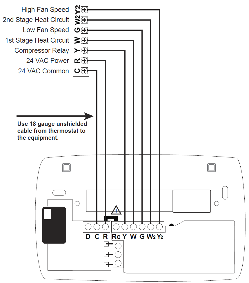
- For a Two Transformer System – remove jumper between R and Rc. Connect the 24VAC power for energizing the unit’s Compressor to thermostat’s (R) terminal. Connect second 24VAC power to thermostat’s (Rc) terminal.
Heat Pump Wiring Guide
5 Wire, 24VAC Heat Pump 1 stage cooling with 1 stage heat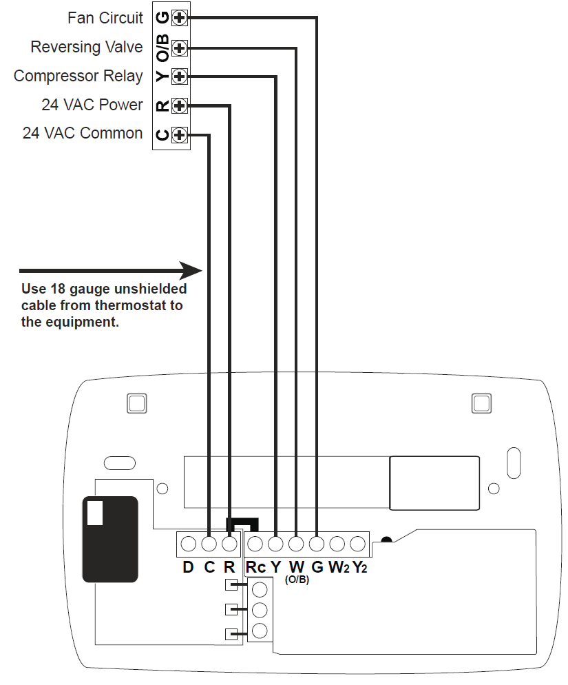
6 Wire, 24VAC Heat Pump 2 stage cooling with 2 stage heat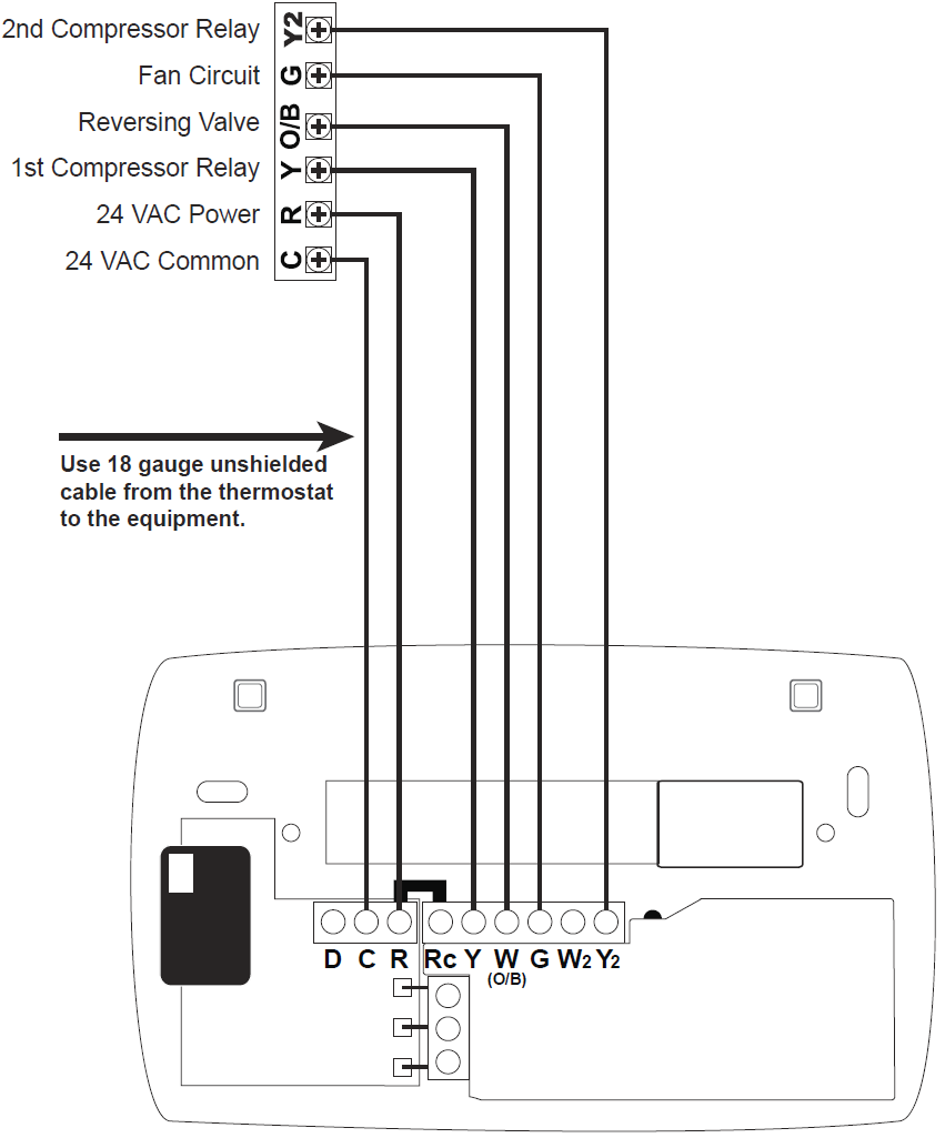
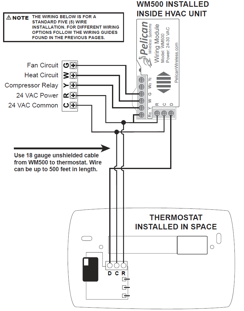
Optional Three Wire Installation
Some installations may have limited in-wall wire. In these cases, the TS250 can accommodate the use of only three wires and still provide control over the entire HVAC unit. To accomplish a three wire installation follow the steps outlined below:
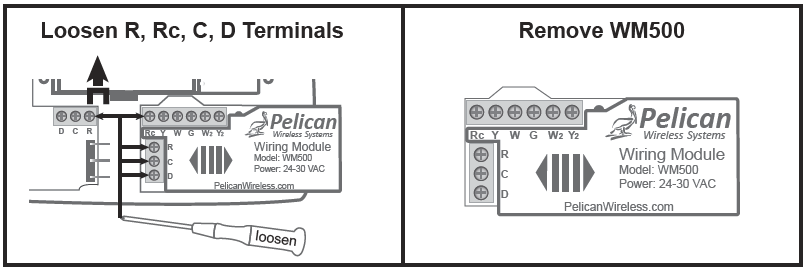
- Loosen R and Rc terminal screws to remove jumper.
- Loosen R, C, and D terminal screws on the Wiring Module (WM500).
- Gently slide the WM500 to the right and remove module from the rear of the thermostat. The WM500 will slide out with very little force.
- Mount the WM500 inside the HVAC unit. Follow the Wiring Guide section (pg. 4 – 13) of this installation guide for directions on how to wire the WM500 to your type of HVAC unit.
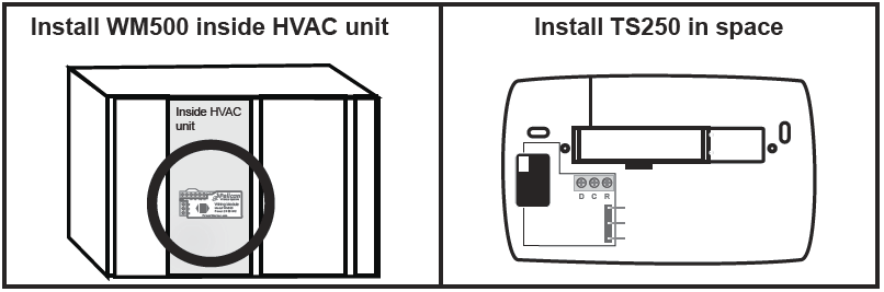
- Use the existing in-wall 18 gauge unshielded wire to connect the R, C, D terminals from the WM500 to the matching R, C, D terminals at the thermostat
Thermostat Configuration
All configuration settings are made Online through the Pelican Web App. Each thermostat will automatically join the Pelican Web App and will be listed both as a notification and as a new thermostat under Admin. The thermostat is intially listed by it’s serial number. Most configurable items can be left at their default settings. For proper operation it is necessary to set the correct System Type (Conventional or Heat Pump). If the Web App is not accessable, the thermostat’s System Type can be set directly using the thermostat front keypad.
Setting System Type Using Thermostat Keypad
The thermostat can be placed into the correct system type (conventional or heat pump) during the first minute after the unit has been powered on. If the thermostat has been running for longer than one minute, remove the front cover of the thermostat from the rear base and then re-attach. This will cause it to recycle the power.
Within the first minute of the thermostat powered on, press and hold the up and down arrows simultaneously for five seconds. This will place the thermostat in configuration mode and the display will change to show one of the three possible system type settings: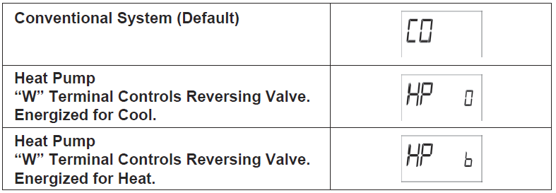
The system type can be changed by pressing the up arrow on the thermostat. Once the correct setting is displayed, press any other button, the thermostat will save the setting and return to normal operation.
Pelican Wireless Systems. All Rights Reserved.
Phone: 888-512-0490
Website: www.pelicanwireless.com
Reference
Download Manual:
Pelican TS250 Programmable Thermostat Installation Guide
Other Manual:
Pelican TS250 Programmable Thermostat Product Specification Guide
Leave a Reply