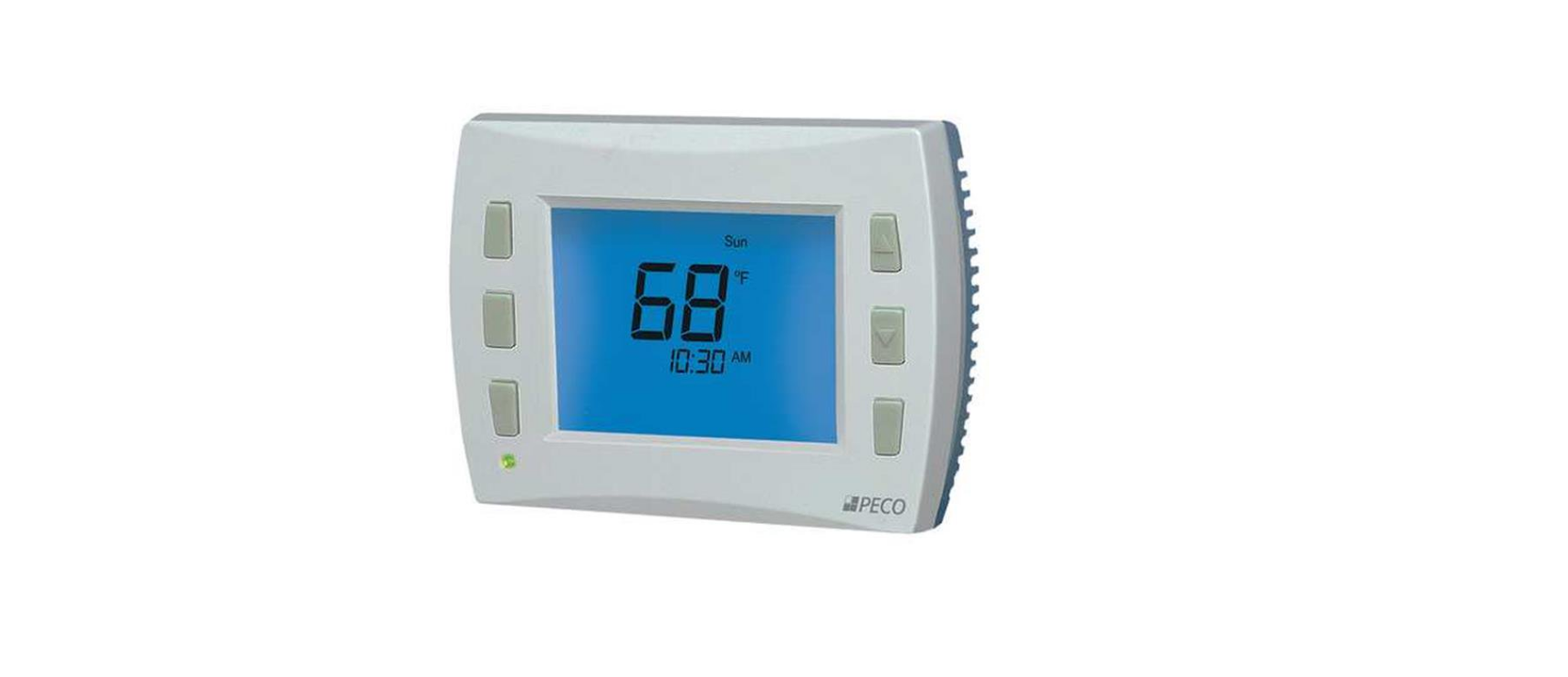
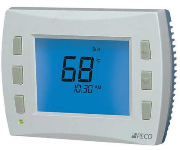
Peco T12532-IAQ Programmable Thermostat
SeT clocK, Year, Month, Day
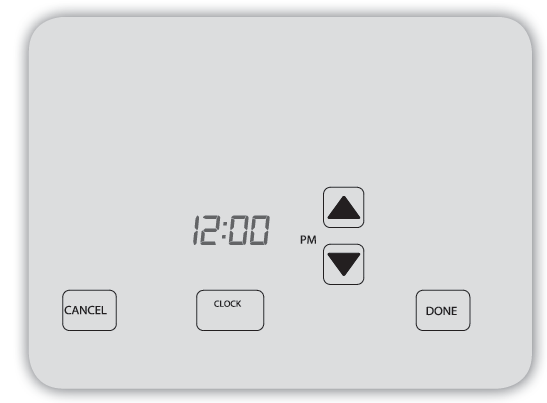
- Press ▲/ ▼ to select 12 or 24 Hr mode, then press Clock.
- Press ▲/ ▼to select the hour, then press Clock.
- Press ▲/ ▼to select minutes, then press Clock.
- Press ▲/ ▼ to select the year, then press Clock.
- Press ▲/ ▼ to select month, press Clock.
- Press ▲/ ▼ to select the calendar day number.
- Press Done to complete the operation.
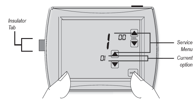
- Press the touchscreen, lower left, and lower right, for about fi ve seconds to access Service Menus.
- Press the cool ▲/ ▼ button to select Service Menu.
- next, press ▲/ ▼ to select the (flashing) option in Service Menu.
- repeat steps 2, 3, to complete confi duration.
- Press did when complete.
Note: Upon completion of installation, remove the plastic insulator tab from the back side of the thermostat.
The following Service Menus (SM) commonly require confi guration. Please verify that these are set for your specifi c application. additional confi duration may be required. refer to Table 2 for all available Service Menus.
- SM 100 = Schedule format and Programmable or nonprogrammable
- SM 110 = System Type
- SM 120 = fan control
- SM 130 = changeover (reversing) valve
- SM 240 = number of Program Periods
- SM 260 = Temperature format (°f or °c)
- SM 340 = Keypad lockout
Wiring: TerMinal deSignaTionS
- connect wires for the appropriate system type (Table 1).
WARNING: DISCONNECT POWER BEFORE BEGINNING INSTALLATION.- CAUTION: Use copper wire only. Insulate or wire-nut all unused leads.
- Use care to avoid electrostatic discharge to the thermostat
- CAUTION: Do not connect unused wires together
- ALL ELECTRICAL LOADS MUST BE CONNECTED TO TERMINAL C (24 VAC).
Table 1. Terminal blocK deSignaTionS
Fan Coil (Conventional) Heat Pump
| C | 24 VAC, Unswitched side | C | 24 VAC, Unswitched side |
| W1 | Stage 1 Heat | B/O | Reversing Valve |
| W2 | Stage 2 Heat | AUX | Auxiliary Heat (Stage 3) |
| G | FAN | G | FAN |
| A | Economizer/Damper/Humidity | A | Economizer/Damper/Humidity |
| E | Stage 3 Heat | E | Emergency Heat |
| Y1 | Stage 1 Cool | Y1 | Compressor Stage 1/Heat/Cool 1 |
| Y2 | Stage 2 Cool (or Dehumidify) | Y2 | Compressor Stage 2/Heat/Cool 2
(or Dehumidify) |
| RH | 24 VAC Power for heating, switched side | RH | 24 VAC Power for heating, switched side |
| RC | 24 VAC Power for cooling, switched side | RC | 24 VAC Power for cooling, switched side |
| SC | Sensor Common | SC | Sensor Common |
| S1 | Indoor Remote Sensor | S1 | Indoor Remote Sensor |
| S2 | Occupancy Setback Input* | S2 | Occupancy Setback Input* |
|
S3 |
Outdoor Remote Sensor |
S3 |
Outdoor Remote Sensor |
Contact PECO to learn more about Occupancy Setback Input sensor applications
Table 2. advanced configuraTion: Service MenuS
Some Service Menus may not be available, depending on the system type (SM 110).
| MENU | FEATURE | OPTIONS | STD. DEFAULT | DESCRIPTION / COMMENTS |
| 100* | Schedule Format | 0-3 | 1 | Select the schedule format on the T12000 Series. (Menu not available on non-programmable thermostats.)
0 = nonprogrammable 1 = programmable 2 = 5-1-1 schedule 3 = 5-2 schedule |
| 101 | Daylight-Saving Time | 0,1 | 0 | Select daylight-saving time as it follows standard format in U.S.: It begins second Sunday of March at 2:00 AM and ends on the first Sunday of November at 2:00 AM.
0 = Disabled 1 = Enabled (2007 U.S. Format) |
| 110 | System Type | 1-13 | 1 | Select the appropriate system configuration (determines available Service Menus). 1 = 1 Heat/1 Cool conventional
2 = 1 Heat/1 Cool heat pump 3 = Heat only without fan (2-wire systems) 4 = Heat only with fan 5 = Cool only 6 = 2 Heat/1 Cool heat pump (with auxiliary heat) and Emergency (Em) heat 7 = 2 Heat/2 Cool multistage conventional 8 = 2 Heat/ 1 Cool multistage conventional 9 = 1 Heat/ 2 Cool multistage conventional 10 = 2 Heat/ 2 Cool heat pump (no auxiliary heat) 11= 3 Heat/ 2 Cool heat pump (with auxiliary heat) and Emergency (Em) heat 12 = 3 Heat/ 1 Cool conventional 13= 3 Heat/ 2 Cool conventional |
| 120 | Fan Control (heating) | 0,1 | 0 | 0 = Fossil Fuel: Gas/Oil/Propane heat (equipment controls heating fan) 1 = Electric Furnace (thermostat controls heating fan) |
| 130 | Changeover valve (B/O terminal) | 0,1 | 0 | 0 = B/O terminal controls valve in cooling 1 = B/O terminal controls valve in heating |
| 140 | Auxiliary Heat | 0,1 | 0 | 0 = Electric backup heat
1 = Fossil fuel backup heat |
| 150 | Backlight | 0,1 | 0 | 0 = Backlight temporarily on
1 = Backlight always on (low intensity, 24V only) |
| 170 | Remote Sensor | 0-5 | 0 | Select sensor if used. Contact PECO for information on the T12000 Series Indoor Remote Zone Sensor.
0 = No Sensor 1 = Indoor Sensor 2 = Outdoor Sensor display only 3 = Outdoor Sensor display and lockout control 4 = Indoor, Outdoor Sensor display only 5 = Indoor, Outdoor Sensor display and lockout control |
| 180 | Heat Pump | 0-45°F | 0 | If an outside sensor is used, the compressor will be locked out when the outside air temp is below |
| Compressor Lockout | (-18°C – 7°C) | the value selected. | ||
| 0 = None | ||||
| 15°F( -9°C); 20°F (-7°C); 25°F ( -4°C); 30°F ( -1°C); 35°F (2°C); 40°F (4°C); 45°F (7°C) | ||||
| 190 | Heat Pump Auxiliary | 0- 60°F | 0 | If an outside sensor is used, the auxiliary heat will be locked out when the outside air temperature |
| Lockout | (-18°C – 15°C) | is above the value selected. | ||
| 0 = None | ||||
| 40°F (4°C); 45°F (7°C); 50°F (10°C); 55°F (13°C); 60°F (16°C) | ||||
| 230 | Furnace Filter | 0; 30; 60; 90; | 0 | Set a filter reminder timer; appears on digital display when the timer expires (if programmed). |
| Change Reminder | 120; 365 | 0 = Off | ||
| 10 days; 30 days; 60 days; 90 days; 120 days; 365 days | ||||
| 240 | Number of Program Periods | 2; 4 events | 4 | 2 = 2 events per day
4 = 4 events per day |
| 250 | Clock format | 12 or 24 Hours | 12 | 12 = 12-hour clock mode 24 = 24-hour clock mode |
| 260 | Temperature Format (°F or °C) | 0,1 | 1 | 0 = Celsius
1 = Fahrenheit |
| 270 | Fan Off Delay Heat | 0-99 Seconds | 0 | Select the amount of time (in seconds) that the fan will run after the thermostat heat outputs are turned off. |
| 280 | Fan Off Delay Cool | 0-99 Seconds | 0 | Select the amount of time (in seconds) that the fan will run after the thermostat cool outputs are turned off. |
| MENU | FEATURE | OPTIONS | STD. DEFAULT | DESCRIPTION / COMMENTS |
| 290 | Range Low | 50-90 °F or
10-32°C |
50°F (10°C) | Choose the lowest selectable temperature setpoint value. |
| 300 | Range High | 50-90 °F or
10-32°C |
90°F (32°C) | Choose the highest selectable temperature setpoint value. |
| 310 | Setback Low | Off; 50-82°F or 11-27°C | 55°F (13°C) | Select the heat setpoint for setback mode. 0 = Off
50-82°F (11-27°C) |
| 320 | Setback High | Off; 58-90°F or 11-32°C | 90°F (32°C) | Select the cool setpoint for setback mode. 0 = Off
58-90°F (11-32°C) |
| 330 | Zone Temp Offset | +/-9°F or +/- 4.5°C | 0°F (18 °C) | Adjusts the displayed value; may differ from actual zone temperature. |
| 340 | Keypad Lockout | 0-3 | 0 | Restricts access to certain features of the device; Service Menu is still available if enabled. 0 = No keypad lockout (Default)
1 = Disables Schedule and System keys 2 = Disables Schedule, System, and Fan keys 3 = Disables all keys |
| 341 | Enable Pin Access | 0,1 | 0 | Applies a 3-digit access code to enter Service Menu 342 0 = Disable
1 = Enable |
| 342 | Set PIN Access Code | 000-999 | 000 | Choose a 3-digit code. |
| 350 | Fan Mode Enable | 1-3 | 3 | 1 = ON: Fan is turned on regardless of demand.
2 = Auto: Fan is turned on according to heating or cooling demand. 3 = ON or Auto: Allows occupant to select either 1 or 2 above. |
| 360 | System Mode Enable | 0-3 | 1 | Allows ability to determine which system modes the occupant can select.
0 = OFF, Auto (0 is NOT valid for following configurations: Heat Only; Cool Only.) 1 = OFF, Heat, Cool, Auto 2 = OFF, Heat, Cool 3 = Heat, Cool, Auto |
| 370 | Economizer/Outside Air Damper | 0-4 | 0 | 0 = Off
1 = Time Based Output 2 = Economizer 3 = Continuous Outside Air Damper 4 = Cycled Outside Air Damper |
| 380 | Minimum Deadband Adjustment | 3-10°F, 1.5-5°C | 3°F | Select a changeover deadband value to prevent short cycling between heating and cooling modes. The value is adjustable to meet various HVAC system requirements. |
| 390 | Pre-Occupancy Purge | 0-3 hours | 0 hours | Select to energize fan for selected number of hours (0-3) prior to all occupied events. |
| 395 | Maximum Override Time Limit | 0=Time until next event; or
1-4 hours |
3 | Restricts the duration that a temporary hold can be set. The temporary hold is limited by the maximum amount of time as defined in this Service Menu.
0 = Remainder of time until the next scheduled event. 1 = 1 Hour 2 = 2 Hours 3 = 3 Hours 4 = 4 Hours |
| 400 | Cycles Per Hour (CPH) Cooling Stage 1 | 0-6 CPH | 0 CPH | Defines the number of cycles per hour for cooling (Stage 1). Select 0 to enable ON-OFF control for Stage 1 cooling. |
| 410 | Cycles Per Hour (CPH) Cooling Stage 2 | 0-6 CPH | 0 CPH | Defines the number of cycles per hour for cooling (Stage 2). Select 0 to enable ON-OFF control for Stage 2 cooling. |
| 420 | Cycles Per Hour (CPH) Heating Stage 1 | 0-12 CPH | 0 CPH | Defines the number of cycles per hour for heating (Stage 1). Select 0 to enable ON-OFF control for Stage 1 heating. |
| 430 | Cycles Per Hour (CPH) Heating Stage 2 | 0-12 CPH | 0 CPH | Defines the number of cycles per hour for heating (Stage 2). Select 0 to enable ON-OFF control for Stage 2 heating. |
| 450 | Cycles Per Hour (CPH) Emergency Heating &
Stage 3 Heat |
0-12 CPH | 0 CPH | Defines the number of cycles per hour for heating. Select 0 to enable ON-OFF control for Emergency Heating & Stage 3 Heat. |
| MENU | FEATURE | OPTIONS | STD.MODEL DEFAULT | DESCRIPTION / COMMENTS |
| 460 | Heat Recovery Rate | 0-18°F/Hr
0-10°C/Hr |
0 °F/Hr | Defines the rate at which the device achieves the heat comfort setpoint. Select 0 to disable ramp recovery. |
| 470 | Cool Recovery Rate | 0-18°F/Hr
0-10°C/Hr |
0°F/Hr | Defines the rate at which the device achieves the cool comfort setpoint. Select 0 to disable ramp recovery. |
| 480 | Minimum Off Time | 1-10 minutes | 4 minutes | Sets the minimum off time for both the heat and cool output. |
| 490 | Humidity Control Enable
(Select models only) |
0-3 | 0 | Selects how humidity will be controlled. When dehumidify control is enabled, the Y2 terminal becomes dehumidify. Note: If option 3 is selected, Service Menu 491 becomes available.
0 = Disabled 1 = Dehumidify Control 2 = Humidify Control 3 = Dehumidify and Humidify Control |
| 491 | Humidity Deadband | 10-50 | 30% relative humidity (RH) | Selects the deadband in %RH between the humidify and dehumidify setpoints. Note: If option 3 is selected in Service Menu 490, Service Menu 491 becomes available.
10; 20; 30; 40; 50 |
| 500 | Programmable/ Intermittent Fan | 0-2 | 0 | 0 = Disable
1 = Programmable Fan: Fan operates continuously in occupied periods or with demand in unoccupied periods. 2 = Intermittent Fan: Fan operates based on the on and off times set in menus 501 and 502. |
| 501 | Intermittent Fan On Time | 1-60 minutes | 5 minutes | Defines the on time for the Intermittent Fan. |
| 502 | Intermittent Fan Off Time | 0-60 minutes | 25 minutes | Defines the off time for the Intermittent Fan. Select 0 for continuous fan. |
| 510 | Power Harvesting Enable
(For use on systems in which a Common “C” power wire is unavailable) |
0-3 | 0 | Options 1-3 draw a small amount of current from load wire indicated to supplement battery supply. 0 = No power harvesting is available. Warning: Power Harvesting is intended to be used
1 = Use Y1 as the battery supplement. only as a battery supplement. If enabled, the feature 2 = Use W1 as the battery supplement. preserves battery life. If Power Harvesting is not 3 = Use both Y1 and W1 as the battery supplement compatible with your system, select “0” (default) to disable. If thermostat is powered from AC, select only “0” or off. Consult a technician if you have questions. |
| 520 | Default Display Icons | 0-4 | 0 | Select icons that will be displayed in the Default Display screen. 0 = Time, Temp, SP
1 = Time, Temp 2 = Time 3 = Temp 4 = None |
| 530 | Revision | — | — | Displays firmware revision information (for technician); not adjustable. |
| 540 | Factory Default Reset | 0,1 | 0 | Select 1 (enable) to restore factory default settings for thermostat. Select 0 to disable. 0 = Disable
1 = Enable Note: Press “Done” key to complete process. |
| 600 | System Test Main Output (Cool) | 0-2 | 0 | Select an option to activate the fan output for 10 minutes; select 0, Done or a different Service Menu to disable.
0 = Disable 1= Cool Stage 1 2 = Cool Stage 2 |
| 610 | System Test Main Output (Heat) | 0-3 | 0 | Select an option to activate the fan output for 10 minutes; select 0, Done or a different Service Menu to disable. Note: Outputs will be activated based upon the system configuration.
0 = Disable (Default) 1 = Heat Stage 1 2 = Heat Stage 2 3 = Heat Stage 3 |
| 620 | System Test Fan Output | 0,1 | 0 | Select 0 or 1 to activate the fan output for 10 minutes; select 0, Done or a different Service Menu to disable.
0 = Disable Fan Output 1 = Enable Fan Output Note: Outputs will be activated based upon the system configuration. |
| 630 | System Test Emergency Output | 0,1 | 0 | Select 0 or 1 to activate the Emergency output for 10 minutes; select 0, Done or a different Service Menu to disable.
0 = Disable Emergency Output 1 = Enable Emergency Output |
| 640 | System Test Economizer | 0,1 | 0 | Select 1 to activate the Economizer output for 10 minutes; select 0, Done or a different Service Menu to disable.
0 = Disable Economizer Output 1 = Enable Economizer Output |
REFERENCE:
Download Manual:
Peco T12532-IAQ Programmable thermostat Quick Start Guide
Other Manual:
Peco T12532-IAQ Programmable thermostat Installation Guide
Peco T12532-IAQ Programmable thermostat Operation Manual
![]()
Leave a Reply