
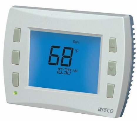
Peco Multi-Fan Programmable Thermostat
SET CLOCK, YEAR, MONTH, DAY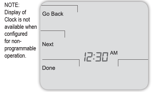
- Press ▲/ ▼ to select 12 or 24 HR mode, then press Next.
- Press ▲/ ▼to select the hour, then press Next.
- Press ▲/▼to select minutes, then press Next.
- Press ▲/ ▼ to select the current year, then press Next.
- Press ▲/ ▼ to select the current month, and press Next.
- Press ▲/ ▼ to select the calendar day number.
- Press Done to complete the operation.
Note: Select More > Clock, to access after setup
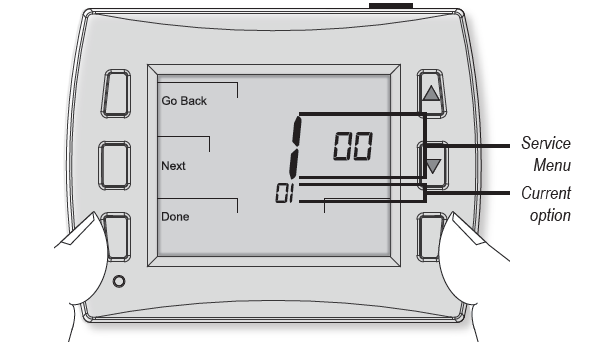
- Hold the lower right and lower left keys for five seconds.
- Press the Next or Go Back button to select a Service Menu.
- Press ▲/ ▼ to select the option.
- Press Done when complete
CONFIGURE SERVICE MENUS
The following Service Menus (SM) commonly require configuration. Please verify that these are set for your specific application. Additional configurations may be required. Refer to Table 2 for all available Service Menus.
- SM 100 = Programmable or Nonprogrammable
SM 110 = System Type - SM 121 = Number of Fan Speeds
- SM 130 = Reversing Valve
- SM 135 = W1 heat output NO or NC
- SM 170 = Remote Sensors
- SM 265 = Single or Dual Setpoint Operation
WIRING
TERMINAL DESIGNATIONS
- Connect wires for the appropriate system type (Table 1).
WARNING: DISCONNECT POWER BEFORE BEGINNING INSTALLATION.
- CAUTION: Use copper wire only. Insulate or wire-nut all unused leads.
- Use care to avoid electrostatic discharge to the thermostat
- CAUTION: Do not connect unused wires together
ALL ELECTRICAL LOADS MUST BE CONNECTED TO TERMINAL C (24 VAC).
TABLE 1. TERMINAL BLOCK DESIGNATIONS
| C | 24 VAC, Unswitched side | C | 24 VAC, Unswitched side |
| W1 | Stage 1 Heat | B/O | Reversing Valve |
| W2 | Stage 2 Heat | AUX | Auxiliary Heat (Stage 2 or 3) |
| G | FAN High | G | FAN High |
| A | FAN Medium | A | FAN Medium |
| E | FAN Low | E | FAN Low |
| Y1 | Stage 1 Cool | Y1 | Compressor Stage 1 |
| Y2 | Stage 2 Cool | Y2 | Compressor Stage 2 |
| RH | 24 VAC Power for heating, switched side | RH | 24 VAC Power for heating, switched side |
| RC | 24 VAC Power for cooling, switched side | RC | 24 VAC Power for cooling, switched side |
| SC | Sensor Common | SC | Sensor Common |
| S1 | Indoor Remote Sensor | S1 | Indoor Remote Sensor |
| S2 | Occupancy Sensor | S2 | Occupancy Sensor |
|
S3 |
Seasonal Changeover Switch OPEN=Cooling in Summer CLOSED=Heating in Winter |
S3 |
NA |
TYPICAL FAN COIL WIRING DIAGRAM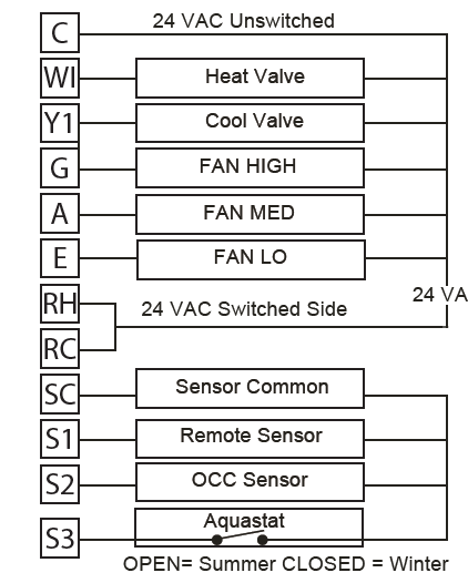
FAN SPEED SELECTION
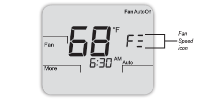 Press the Fan button to select speed/operation.
Note: Fan Speed is noted as follows:
- Press Done when complete.
ON = Continuous Fan Operation
AUTO = Fan Cycles with Heating and Cooling
TABLE 2. ADVANCED CONFIGURATION: SERVICE MENUS
Some Service Menus may not be available, depending on the system type (SM 110).
| MENU | FEATURE | OPTIONS | STD. DEFAULT | DESCRIPTION / COMMENTS |
| 100 | Schedule Format | 0-3 | 1 | Select the schedule format on the T8000 Series. (Menu not available on non-programmable thermostats.)
0 = nonprogrammable 1 = programmable 2 = 5-1-1 schedule 3 = 5-2 schedule |
| 101 | Daylight-Saving Time | 0,1 | 0 | Select daylight-saving time as it follows standard format in U.S.: It begins second Sunday of
March at 2:00 AM and ends on the first Sunday of November at 2:00 AM. 0 = Disabled 1 = Enabled (2007 U.S. Format) |
| 110 | System Type | 1-13 | 1 | Select the appropriate system configuration (determines available Service Menus).
1 = 1 Heat/1 Cool conventional 2 = 1 Heat/1 Cool heat pump 3 = Heat only without fan (2-wire systems) 4 = Heat only with fan 5 = Cool only 6 = 2 Heat/1 Cool heat pump (with auxiliary heat) 7 = 2 Heat/2 Cool multistage conventional 8 = 2 Heat/ 1 Cool multistage conventional 9 = 1 Heat/ 2 Cool multistage conventional 10 = 2 Heat/ 2 Cool heat pump (no auxiliary heat) 11= 3 Heat/ 2 Cool heat pump (with auxiliary heat) 12 = NA 13= NA |
| 120 | Fan Control (heating) | 0,1 | 1 | 0 = Fossil Fuel; Gas/Oil/Propane heat (equipment controls heating fan) 1 = Electric Furnace (thermostat controls heating fan) |
| MENU | FEATURE | OPTIONS | STD. DEFAULT | DESCRIPTION / COMMENTS |
| 121 | Fan Speeds | 1, 2, 3, 4 | 3 | Allows selection of multiple fan speeds. 1 = Single speed Fan (G terminal)
2 = 2-speed Fan (G and E Terminals) 3 = 3-speed Fan (G,A and E Terminals) 4 = 3-speed Staged Fan |
| 130 | O/B Reversing valve | 0,1 | 0 | When 0, output is active for cooling. When 1, output is active for heating. 0 = (O) Active with cooling
1 = (B) Active with heating |
| 135 | W1 Output
Configuration |
0,1 | 0 | Changes operation of W1 for Active to Open (NC Normally Closed) to Active to Close (NO Normally Open). Must be 0 for heat pump operation.
0 = NC Operation 1 = NO Operation |
| 150 | Backlight | 0,1 | 0 | 0 = Backlight temporarily on
1 = Backlight always on (low intensity, 24V only) |
| 170 | Remote Sensor | 0-8 | 0 | Select sensor if used. Contact PECO for information on the T8000 Series Indoor Remote Zone Sensor. 0 = No Remote Sensors
1 = Remote Indoor Sensor Only 2 = Not Used 3 = Not Used 4 = Not Used 5 = Not Used 6 = S3 Input with Aquastat Only 7 = S3 Input with Aquastat and S1 with Remote Indoor Sensor 8 = Not Used |
| 240 | Number of Program Periods | 2; 4 events | 4 | 2 = 2 events per day (Selections OCC1 and UnOcc1)
4 = 4 events per day (Selections Occ1-UnOcc1-Occ2- UnOcc2) |
| 250 | Clock format | 12 or 24 Hours | 12 | 12 = 12-hour clock mode 24 = 24-hour clock mode |
| 260 | Temperature Format (°F or °C) | 0,1 | 1 | 0 = Celsius
1 = Fahrenheit |
| 265 | Single/Dual Setpoint | 0,1 | 1 | Determines if single user override setpoint is used, or if user sets heat and cool setpoints independently. 0 = Dual Setpoint (Heat and Cool)
1 = Single Override Setpoint (Single Setpoint with auto changeover algorithm) |
| 290 | Range Low | 50-90 °F or
10-32°C |
50°F (10°C) | Choose the lowest selectable temperature setpoint value. |
| 300 | Range High | 50-90 °F or
10-32°C |
90°F (32°C) | Choose the highest selectable temperature setpoint value. |
| 310 | Setback Low | Off; 50-82°F or 11-27°C | 55°F (13°C) | Temperature setpoint thermostat will Heat to when in Setback mode (Off sets Heating to ~45F Setback). 0 = Off
50-82°F (11-27°C) |
| 320 | Setback High | Off; 58-90°F or 11-32°C | 90°F (32°C) | Temperature setpoint thermostat will Cool to when in Setback mode. (Off sets Cooling to ~150F in Setback).
0 = Off (disabled) 58-90°F (11-32°C) |
| 330 | Zone Temp Offset | +/-9°F or +/- 4.5°C | 0°F (18 °C) | Adjusts the sensed Zone Temperature displayed, allowing calibration in the field. |
| 340 | Keypad Lockout | 0-3 | 0 | Restricts access to certain features of device; Service Menu still available if keypad lockout is enabled. 0 = No key pad lockout (Default)
1 = Disables Schedule and System keys 2 = Disables Schedule, System, and Fan keys 3 = Disables all keys |
| 341 | Enable Pin Access | 0,1 | 0 | Applies a 3 digit access code to enter Service Menu 342 0 = Disable
1 = Enable |
| 342 | Set PIN | 000-999 | 000 | Choose a 3-digit PIN access code. |
| 350 | Fan Mode | 1-3 | 3 | 1 = ON: Fan is always on, regardless of demand
2 = Auto: Fan is only on with heating or cooling demand 3 = ON or Auto: Occupant can choose either selection |
| 360 | System Mode | 0-3 | 1 | Allows ability to determine which system modes the occupant can select. 0 = OFF, Auto
1 = OFF, Heat, Cool, Auto 2 = OFF, Heat, Cool 3 = Heat, Cool, Auto |
| MENU | FEATURE | OPTIONS | STD. DEFAULT | DESCRIPTION / COMMENTS |
| 375 | Purge Enable | 0-3 | 0 | 0 = No Purge ▲! WARNING: Service Menu 375 may disable fan operation during valve
1 = W1 purge purge. This feature should be set to 0 (zero) unless outputs are connected 2 = Y1 Purge to hydronic heating or cooling valves. Failure to follow this instruction can 3 = W1 & Y1 purge result in damage to equipment and/or property. |
| 376 | Purge Duration | 1-3 | 1 | Defines how long to open the valve to perform the purge function.
1 to 3 minutes |
| 377 | Purge Frequency | 0-2 | 0 | Defines how long to open the valve to perform the purge function.
0 = Every 24 Hours 1 = Every 12 Hours 2 = Every 6 Hours |
| 380 | Minimum Deadband Adjustment | 1-10°F, 0.5-5°C | 3°F | A changeover deadband value prevents short cycling between heating and cooling modes. The value is adjustable to meet various HVAC system requirements. |
| 395 | Temporary Occupied Duration Limit | 0-4 hours | 0 | The temporary User Override is limited by the time defined in this service menu.
0 = Remainder of time until the next scheduled event. 1 = 1 Hour 2 = 2 Hours 3 = 3 Hours 4 = 4 Hours |
| 480 | Minimum Off Time | Range:
0-10 Minutes |
4 | Sets the minimum off time for both the heat and cool output. |
| 500 | Programmable/ Intermittent Fan | 0-2 | 0 | In programmable mode, fan will operate continuously during occupied periods or with demand during unoccupied periods. In intermittent mode, fan will operate based on the on and off times set in menus 501 and 502 whenever there is no call for fan.
0 = Disable 1 = Programmable Fan: Fan operates continuously in occupied periods or with demand in unoccupied periods. 2 = Intermittent Fan: Fan operates based on the on and off times set in menus 501 and 502. |
| 501 | Intermittent Fan On Time | 1-60 minutes | 5 minutes | Defines the duration in which fan low will be on. Fan On will be activated after Fan Off time has passed. |
| 502 | Intermittent Fan Off Time | 0-60 minutes | 25 minutes | Defines the duration in which fan low will be off. Fan Off will be activated after Fan On time has passed.
A selection of 0 will result in continuous Fan. |
| 520 | Default Display Icons | 0-4 | 0 | Select icons that will be displayed in the Default Display screen. 0 = Time, Temp, SP
1 = Time, Temp 2 = Time only 3 = Temp only 4 = No Display |
| 530 | Revision | — | — | Upon menu selection the firmware revision, firmware checksum and configuration checksum is
displayed. |
| 540 | Factory Default Reset | 0,1 | 0 | When Enable is selected the device will return to factory default settings. 0 = Disable
1 = Enable Note: Press “Done” key to complete process. |
| 600 | System Test Main Output (Cool) | 0-2 | 0 | If either stage is enabled it will activate the associated output for 10 minutes. The Fan output will automatically turn on. If a different service menu is selected the output will be disabled.
0 = Disable 1= Cool Stage 1 2 = Cool Stage 2 |
| 610 | System Test Main Output (Heat) | 0-3 | 0 | If either stage is enabled it will activate the associated output for 10 minutes. The Fan output will automatically turn on if configured to do so. If a different service menu is selected the output will be disabled. (Note: Aux heat could be stage 2 or stage 3 based on configuration)
0 = Disable (Default) 1 = Heat Stage 1 2 = Heat Stage 2 3 = Heat Stage 3 |
| 620 | System Fan Test Output | 0-3 | 0 | 0 = Disabled
1 = Low Speed 2 = Medium Speed 3 = High Speed |
| 900 | Factory Use Only | — | — | Factory Use Only |
| 901 | Factory Use Only | — | — | Factory Use Only |
| 902 | Factory Use Only | — | — | Factory Use Only |
COPYRIGHT 2016 PECO, INC. ALL RIGHTS RESERVED. P/N 70864 3220-2318 REV 04
REFERENCE:
DOWNLOAD MANUALS:
Peco Multi-Fan Programmable Thermostat Quick Start Guide
![]()
Leave a Reply