
napoleon WSC43BA Touchscreen Thermostat
SAFETY HANDLING
WARNING
- Failure to follow these safety notices could result in fire, electric shock, other injuries, or damage to the thermostat and other property. Read all the safety notices below before using the thermostat.
- Avoid high humidity or extreme temperatures.
- Avoid long exposure to direct sunlight or strong ultraviolet light.
- Do not drop or expose the unit to intense vibration.
- Do not disassemble or try to repair the unit on your own.
- Do not expose the unit or its accessories to flammable liquids, gases, or other explosives.
| Product Name | Model Number | FCC ID | IC ID |
| Touchscreen Thermostat | WSC43BA | VA8-WSC43BA | 7114A- WSC43BA |
| Indoor PIR Temperature Sensor |
WSC-IS |
VA8-WSC-IS |
7114A- WSCIS |
| Outdoor Temperature Sensor with Probe |
WSC-OS |
||
| Thermostat Power Module
(not included) |
WSC- PWRM |
N/A |
|
This device complies with Part 15 of the FCC Rules. Operation is subject to the following two conditions: 1) The device may not cause harmful interference; and 2) the device must accept any interference received, including interference that may cause undesired operation. Changes or modifications not expressly approved by the party responsible for compliance could void the user’s authority to operate the equipment.
NOTE: This equipment has been tested and found to comply with the limits for a Class B digital device, pursuant to Part 15 of the FCC Rules. These limits are designed to provide
reasonable protection against harmful interference in a residential installation. This equipment generates, uses, and can radiate radio frequency energy and, if not installed and used in
accordance with the instructions, may cause harmful interference to radio communications. However, there is no guarantee that interference will not occur in a particular installation.
If this equipment does cause harmful interference to radio or television reception which can be determined by turning the equipment off and on, the user is encouraged to try to correct the
interference by one or more of the following measures:
- Reorient or relocate the receiving antenna.
- Increase the separation between the equipment and the receiver
- Connect the equipment to an outlet on a circuit different from that to which the receiver is connected.
- Consult the dealer or an experienced radio/TV technician for help.
NOTE: This device and its antenna(s) must not be co-located or operated in conjunction with any other antenna or transmitter.
RF Exposure Statement
To maintain compliance with FCC’s RF Exposure guidelines, this equipment should be installed and operated with a minimum distance of 20cm from the radiator to your body. This device
and its antenna(s) must not be co-located or operated in conjunction with any other antenna or transmitter.
NOTE: The information throughout this manual is believed to be correct at the time of printing. Wolf Steel Ltd. reserves the right to change or modify any information within this manual at any time without notice. Changes, other than editorial, are denoted by a vertical line in the margin.
WELCOME
The EQHub thermostat makes it easier and smarter to control your household temperature. You can control and switch easily between dual fuel sources using custom hybrid heating modes. With the help of indoor and outdoor sensors, you can balance hot or cold spots throughout the home to achieve the best comfort or select specific sensors for target temperatures. You can also set schedules for your thermostat, so it operates automatically based on the selected time periods and settings.
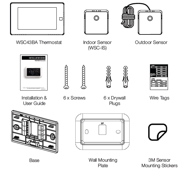
IN THE BOX
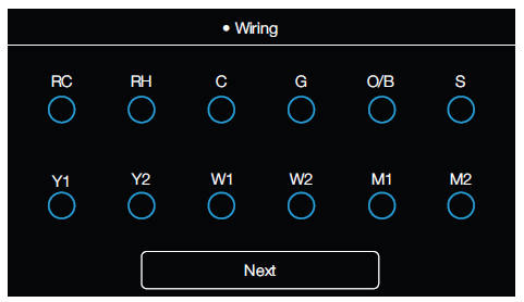
WIRING DIAGRAMS
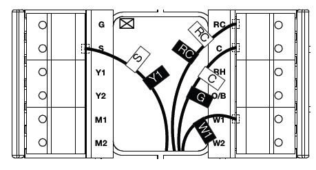
Below are the wiring diagrams for common HVAC equipment.
Conventional Heating and Cooling System
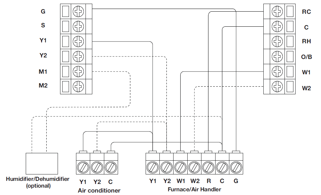
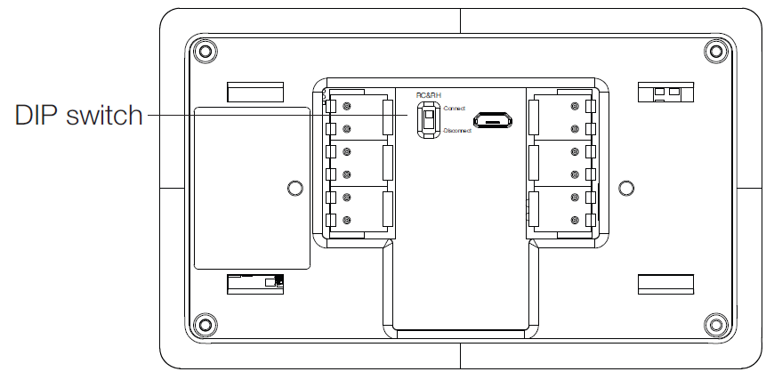
Remove the jumper between Rh, Rc, or R terminals. Adjust the DIP switch on the back of the thermostat to “Disconnect” if you have connected both RC-wire and RH-wire to the wall plate. Otherwise, switch it to the “Connect” side.
Heat Pump with Furnace
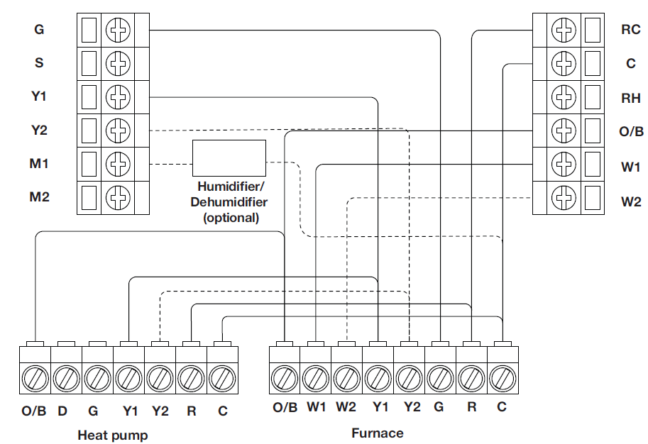
Remove the jumper between Rh, Rc, or R terminals. Adjust the DIP switch on the back of the thermostat to “Disconnect” if you have connected both RC-wire and RH-wire to the wall plate. Otherwise, switch it to the “Connect” side.
Heat Pump with Air Handler
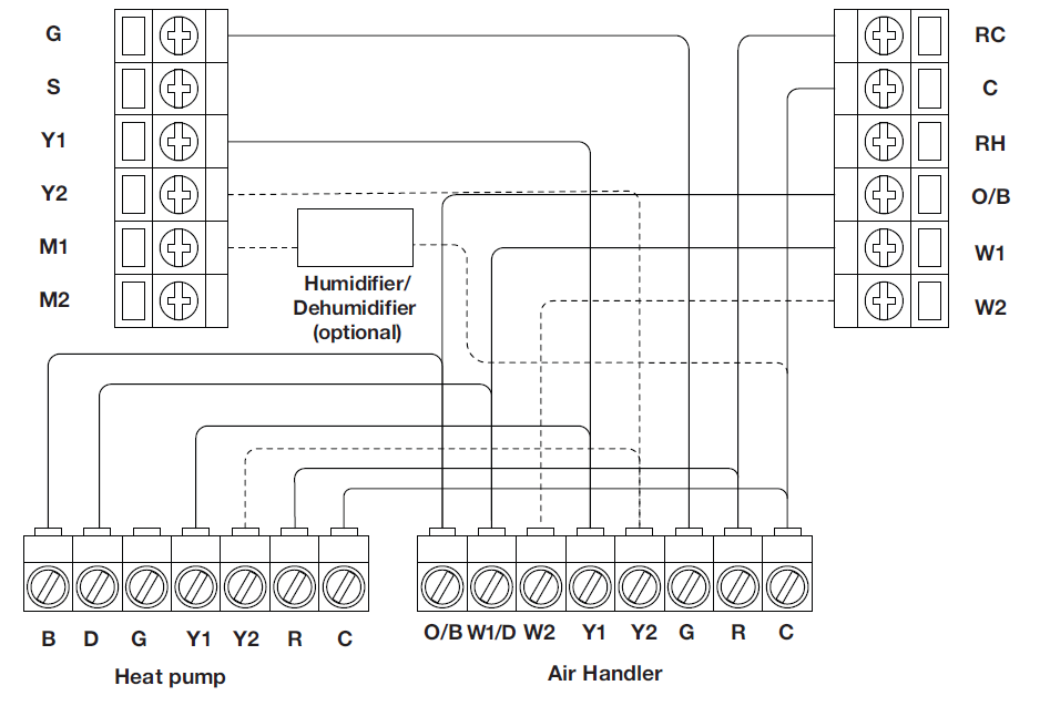
Remove the jumper between Rh, Rc, or R terminals. Adjust the DIP switch on the back of the thermostat to “Disconnect” if you have connected both RC-wire and RH-wire to the wall plate. Otherwise, switch it to the “Connect” side.
Boiler or Radiant System with Air Handler and
Conventional Cooling or Heat Pump
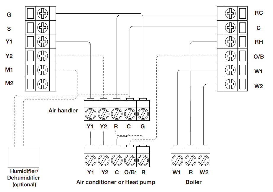
Remove the jumper between Rh, Rc, or R terminals. Adjust the DIP switch on the back of the thermostat to “Disconnect” if you have connected both RC-wire and RH-wire to the wall plate. Otherwise, switch it to the “Connect” side.
INSTALLATION GUIDE
REMOVING YOUR OLD THERMOSTAT
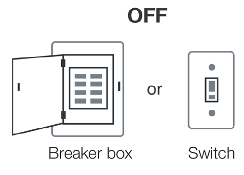
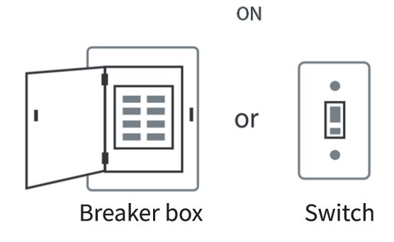
Step 1: Switch off your HVAC system Before you start, please switch off your HVAC system to protect you and to avoid blowing a fuse. Wait a few minutes, then try to adjust the temperature of your old thermostat to verify that the system is off.
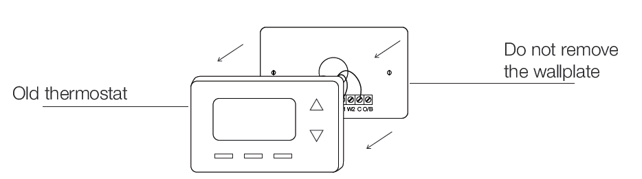
Step 2: Remove the old thermostat Remove the old thermostat from the wall. Keep the wall plate with wires.
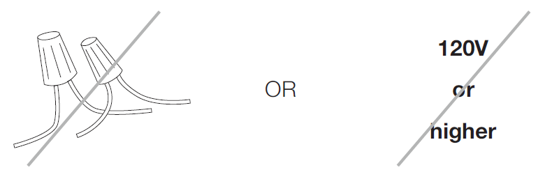
Step 3: Compatibility check
If you find a thick wire with wire nuts on the backplate of the old thermostat, or if the voltage of your old system is 120V or higher, it will not be compatible with WSC43BA. If none of the above is true, please proceed to the next step.
Step 4: Take a photo
Take a photo of the wires connected to the terminal of your old thermostat. You may need to reference this photo later.
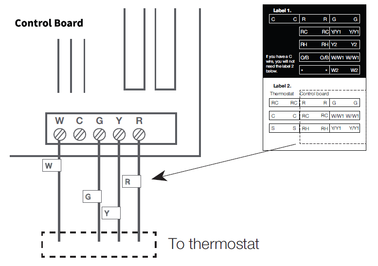
Step 5: Label the wires with tags Label each wire on the wall plate with the tags (label 1) provided, then carefully disconnect the wires.
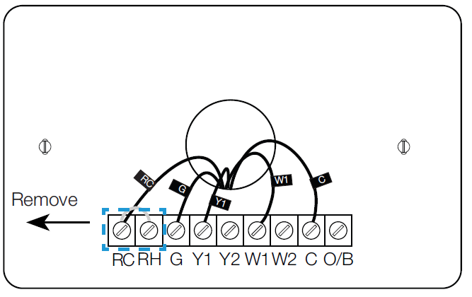
NOTE: If there are any jumper wires between Rh, Rc, or R terminals, do not label them. WSC43BA does not need jumpers. Remove and save them, al
 ong with your old thermostat.
NOTE: For unique wiring situations, see the “Wiring Diagrams” section.
CONNECTING THE WIRES
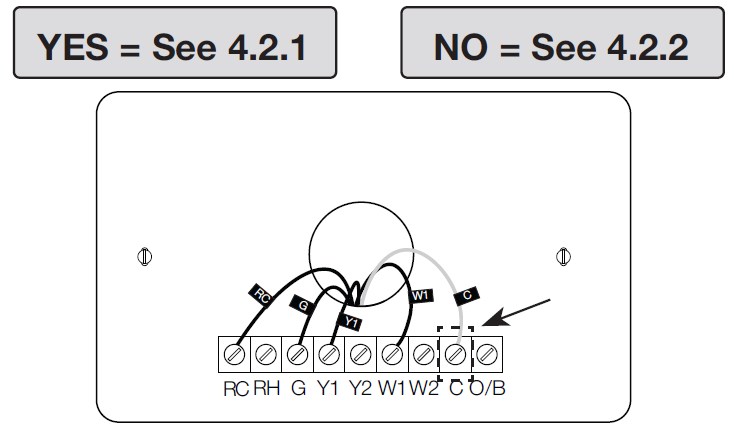
Do you have a C-wire connected to your old thermostat?
Terminal Designation
| Terminals | What It Means |
| RC | 24VAC primary for cooling |
| RH | 24VAC primary for heating |
| C | 24VAC common |
| W1 | 1st stage primary heating relay/AUX heat |
| W2 | 2nd stage secondary heating relay/AUX heat |
| Y1 | 1st stage primary compressor contactor |
| Y2 | 2nd stage secondary compressor contactor |
| G | Fan relay |
| O/B | Changeover valve for heat pumps |
| S | Optional wiring module terminal to combine Y and G, while reserving an extra in-wall wire to power on the thermostat |
INSTALL THE THERMOSTAT WITH A C-WIRE
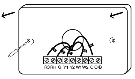
Step 1: Remove the old wall-plate
Unscrew the old wall plate from the wall, then gently pull it out to ensure the wires will not fall back into the hole.
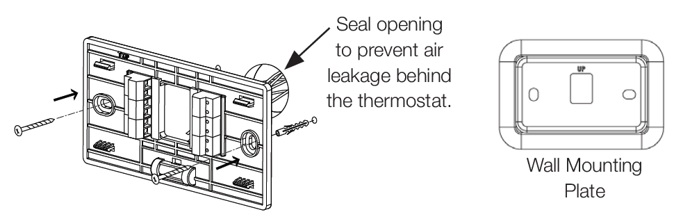
IMPORTANT: It is recommended to seal the wall opening after the thermostat wire has been installed. The opening can be sealed with insulation, foam, and or sealed off with foam tape.
Step 2: Attach the base of WSC43BA to the wall Bundle and insert the wires through the holes of the base of WSC43BA, then attach the base to the wall with screws (supplied). If preferred, the wall mounting plate should be secured to the wall now, pulling the wires through the holes of the mounting plate. Insert the drywall plugs behind the wall plate, screwing the wall plate into the wall first, then screwing the base into the wall, through the wall plate.
Step 3: Connect the wires
Connect the wires to the corresponding terminal in the base. Take a photo of the wires when you are finished. You may need to refer to it later during the setup wizard. Do you have more than one R-wire (R, RC, or RH)?
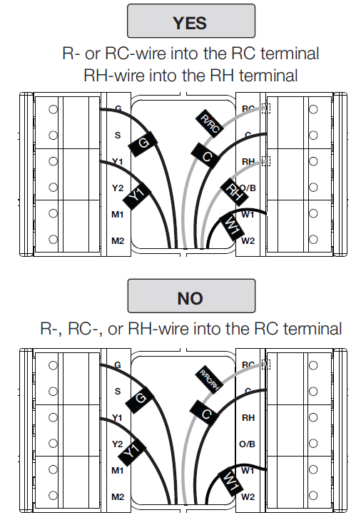
YES
R- or RC-wire into the RC terminal RH-wire into the RH terminal
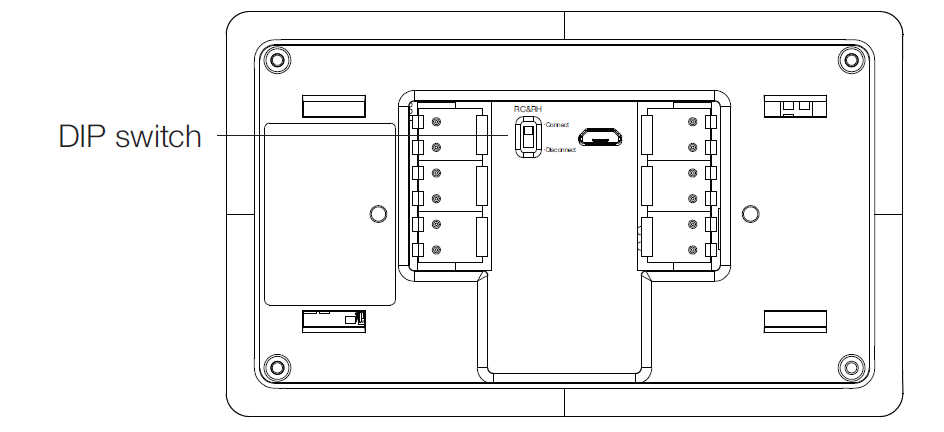
Step 4: DIP switch
Adjust the DIP switch on the back of the thermostat to “Disconnect” if you have connected the RC wire and the RH wire to the wall plate Otherwise, switch it to the “Connect” side.
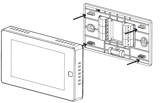
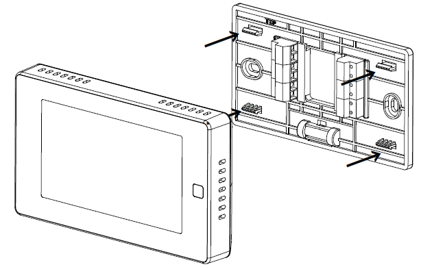
Step 5: Attach the WSC43BA to the base
Gently press the WSC43BA into the base until it clicks.
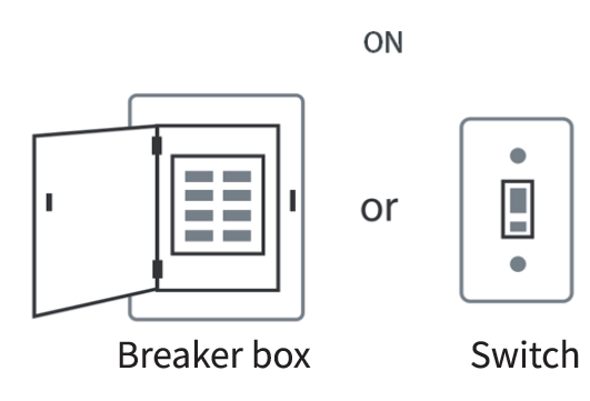
Step 6: Power on your system
Congratulations! The installation is finished. Please power on your HVAC system.
When the power is successfully energized, the thermostat’s screen will light up and go into the setup wizard. You can complete the following configuration according to section 4.
INSTALL THE THERMOSTAT WITHOUT A C-WIRE (OPTIONAL)
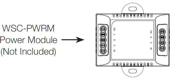 The power module requires your system to have the following wires:
- 4 wires: W/W1, Y/Y1, G, and R (or Rc or Rh)
- Or 3 wires: Y/Y1, G, and R (or Rc or Rh)
If you do not have these wires, your system may not be compatible with the power module
INSTALLATION GUIDE
Description
The C-wire is used to provide power to the thermostat. If your system does not have a C-wire, you can use the power module to power your thermostat, using the existing wires. For certain applications were more than just an additional C-wire is required, the addition of the power module may not be sufficient on its own.
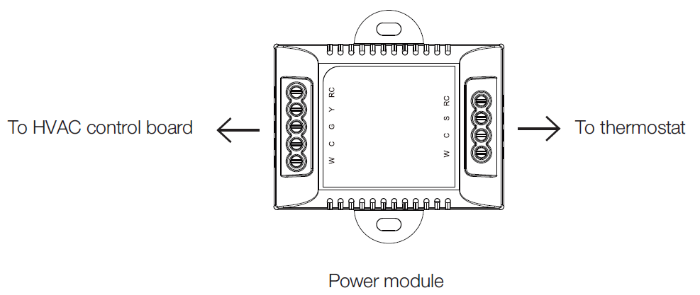
There are two sides with connections. One side (4 terminals) is for thermostat connections; the other side, pre-wired (5 terminals), is for the control board connections.
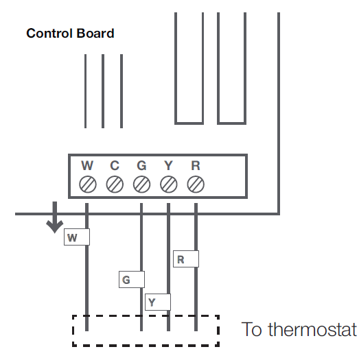
Step 1: Find the HVAC terminals
Find the control board of your HVAC system. Open your HVAC system’s cover and take a photo of the wires connected to the terminals of your old thermostat. You may need to reference this photo later.
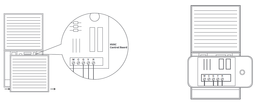
Step 2: Label the wires
Label only the wires from the control board to your old thermostat with the tags provided (label 2 control board).
Step 3: Disconnect the wires
Disconnect the W/W1, G, Y/Y1, and R wires from the control board.
Step 4: Connect the wiring module
Reconnect them correspondingly to the 4 terminals side of the power module.
R -> RC || W/W1 -> W || G -> C || Y/Y1 -> S
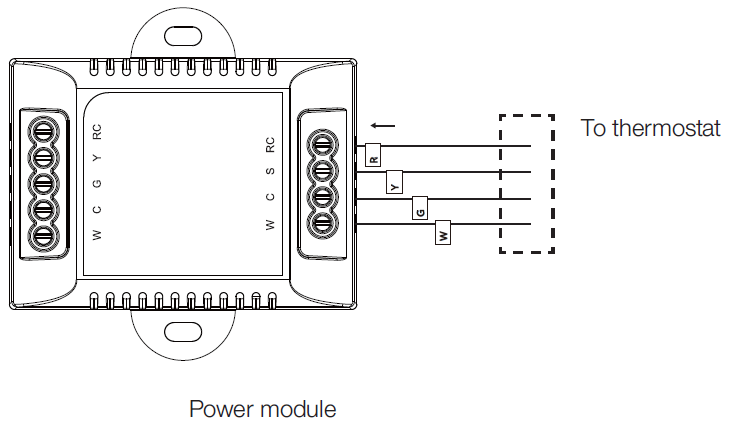
Step 5: Connect the wires
Generally, the control board will have W, C, G, Y, and R terminals. Connect the pre-wired side of the power module (5 terminals) to the corresponding terminals.
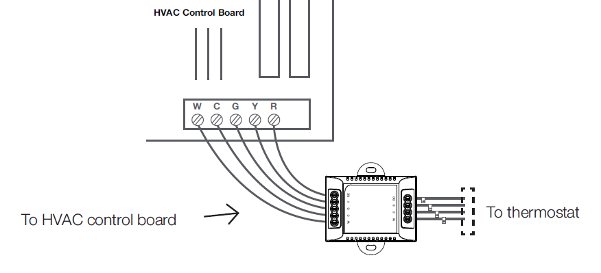
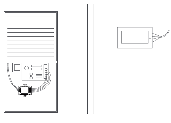
Step 6: Position the wiring module
The power module should be installed between your thermostat wiring and your control board. Install it in the right position, then close the HVAC cover panel securely and return to your thermostat.
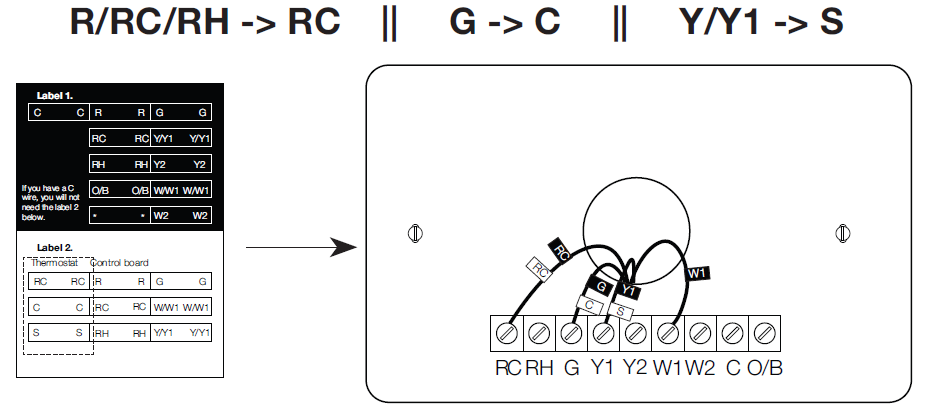
Step 7: Add new tags
Add new tags to the following tags to simplify your wiring:
R/RC/RH -> RC || G -> C || Y/Y1 -> S
Step 8: Remove the wall-plate
Unscrew the wall plate from the wall, then gently pull it out and ensure the wires will not fall back into the hole.
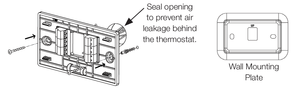
Step 9: Attach the base of WSC43BA to the wall
Bundle and insert the wires through the holes of the base of WSC43BA, then attach the base to the wall with screws (supplied). If preferred, the wall mounting plate should be secured to the wall now, pulling the wires through the holes of the mounting plate. Insert the drywall plugs behind the wall plate, screwing the wall plate into the wall first, then screw the base into
the wall, through the wall plate.
IMPORTANT: It is recommended to seal the wall opening after the thermostat wire has been installed. The opening can be sealed with insulation, foam, and or sealed off with foam tape.
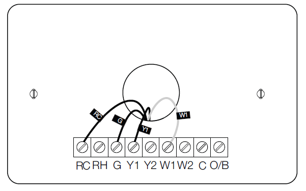
Step 10: Connect the wires
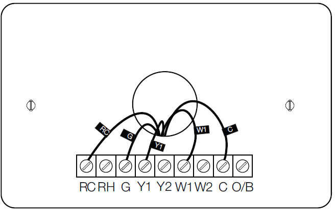
First, connect 3 wires as shown below.
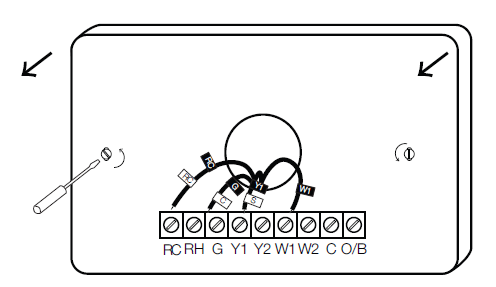
Then connect other wires to the corresponding terminal in the base. Take a photo of the wires when you are finished. You may need to refer to it later during the setup wizard.
Step 11: DIP switch
Adjust the DIP switch on the back of the thermostat to the “Connect” side.
Step 12: Attach the WSC43BA to the base
Gently press the WSC43BA into the base until it clicks.
Step 13: Power on your system
Congratulations! The installation is finished. Please power on your HVAC system.
When the power is successfully energized, the thermostat’s screen will light up and go into the setup wizard. You can complete the following configuration according to section 4.
WIRING CONFIGURATION ON THERMOSTAT
Follow the wizard first to complete the thermostat setup based on your HVAC system.
Heat Pump Type
Choose your heat pump source from the options provided:
- Air to air
- Geothermal
- O/B Setting
Choose the alternative function for your Heat Pump*:
- O/B on cool
- O/B on heat
Consult your heat pump manual to determine the correct O/B setting for your application.
- Heating Type
Select your system’s heating type
- Furnace
- Boiler
Heating Source (Furnace)
Choose your system’s heating source when heating type selected is Furnace.
- Standard efficiency gas forced air
- High efficiency gas forced air
- Oil forced air
- Electric forced air
- Hot water fan coil
Heating Source (Boiler)
Choose your system’s heating source when heating type selected is Boiler:
- Hot water radiant heat
- Steam
Heat Fan Control
Allow the fan to be controlled either by your thermostat or furnace:
- By thermostat
- By furnace
Accessory Configuration
Choose your connected accessory. M1 must be selected in the wiring section for this option to appear:
- Humidifier
- Dehumidifier
- Humidifier Type
Select the Humidifier type if the accessory chosen is Humidifier:
- Evaporative
- Steam
Dehumidifier Active
Select your Humidifier type if the accessory chosen is Dehumidifier:
- Relay is open
- Relay is closed
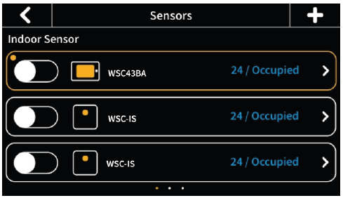
PAIRING INDOOR AND OUTDOOR SENSORS
- Click the “+” button at the top-right corner of the interface in “Menu” -> “Sensors” on the thermostat and tap “Next”.
- Remove the rear cover of the sensor.
- Press and hold the button on the back of the sensor until the indicator on the front of the sensor flashes red.
- Wait for sensors to pair automatically. When the pairing is successful, the sensor flashes green 3 times.
- For Outdoor Sensors only: Place the temperature probe of the sensor outdoors while leaving the main body of the sensor indoors. Make sure the sensor is within 10 meters of
the thermostat.The outdoor sensor is great to use in areas of limited/intermittent internet access or in regions where local weather conditions are different to internet weather forecasts.
You can set the indoor remote sensor as the main sensor or to only participate in the calculation of the average temperature. (Only one sensor can be set as the main sensor at a time). With multiple indoor remote sensors, if one of them is set as the main sensor, the other indoor remote sensors and the built-in sensor will continue to participate, according to the different participation periods set. The thermostat will calculate the average temperature of all the sensors in the occupied state as a reference. If there is no one in the room where the sensor is located, that sensor will not participate in the calculation.
TECHNICAL SPECIFICATIONS
| Compatibility | |
|
Compatible systems |
• Conventional: single-stage heat- ing, 2-stage heating, and 2-stage cooling HVAC systems
• Heat pump: 2-stage heating, 2-stage cooling, 2-aux heating • Humidifier/dehumidifier • Supports natural gas, electric, hot water, steam or gravity, gas fireplac- es (24 volts), oil heat sources, heat pump, dual fuel |
| HVAC Control Functions | |
| System mode | • Heat, Cool, Auto, Off |
| Hybrid mode | • Low Cost, Comfort, Green, Nighttime |
| Fan mode | • On, Auto, Circle (adjustable) |
|
Advanced |
• Setting temperature locally or remotely
• Auto-changeover between heat and cool mode (System Auto) • Compressor protection time is available for select equipment • Failure protection by cutting off all circuit relays • Smart warm-up • Low temperature protection |
| W415-4094 / A / 03.01.23 | |
| Wireless Connectivity | |
| WiFi | • 802.11 b/g/n @ 2.4GHz |
| Radio | • 915MHZ |
| Physical Specifications | |
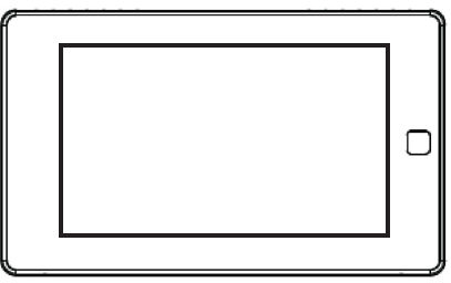
| LCD Screen | • 4.3-inch color touch screen |
| PIR Sensor | • Sensing distance 3m, angle 70° |
| Electrical Rating | • 24 VAC, 1A carry; 5A surge 50/60 HZ |
| Max. Load Current | • 1A |
| Operating Environment | • 0°C~50°C (32°F~122°F)
• Humidity range: 5%~95% |
| Storage Temperature | • 30°C~60°C (-22°F~140°F) |
| Wiring | • 18 AWG, requires both R and C wires from the HVAC system |
| Dimensions | • 131mm (L) x 78mm (W) x 29.2mm (H) |
| Mounting Type | • Wall mounting |
| Indoor and Outdoor Sensors | |
| Battery | • DC 3V (2*AAA batteries) |
| Radio | • 915MHZ |
| LED | • 2-color LED (red, green) |
| PIR | • Detect occupancy
• Sensing distance 5m, angle 120° |
|
Operating Environment |
• 0°C~50°C (32°F~122°F)
(indoor only) • Humidity range: 5%~95% |
| Dimensions | • 62mm (L) x 62mm (W) x 15.5mm (H) |
| Mounting Type | • Wall-mounted or placed on a stable surface (i.e., a tabletop stand) |
| Connectivity Range | 10m |
HOME APP EN
- Access your appliance remotely by downloading the Home App from your app store.
- In order to access the app, you will be required to create an account by following the instructions listed within the app (see below for details).
- By pairing your appliance to the Home App via WiFi, you gain control to all modes and functions of the appliance.
- All notifications and alarms are sent through the app to keep you connected with ease.
Let’s Get Started
- Download the Home App from your app store (Google Play or Apple App Store).
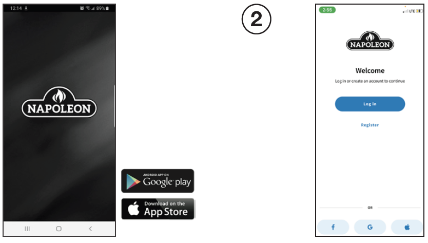
NOTE: This requires Android 7.0 or iOS 11.0. 1 2 - Register an account with the Home App OR sign-in using your Facebook, Google, or Apple account information.
- Enter user information and create a password for the account. Select the country in which the appliance is located.
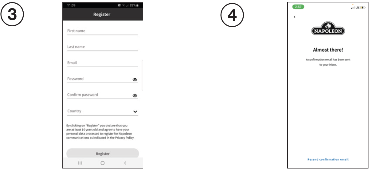
- The information entered in Step 3 will be registered to the Home App and a confirmatio will be sent to the email provided.
- Open email inbox and select the confirmation link.
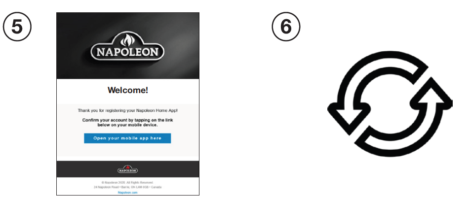
NOTE: The confirmation link must be opened on the device that the Home App is installed on. - If no email is found, click “Re- Send Confirmation Link” and check junk folder.
- Ensure your appliance is plugged in and turned on.
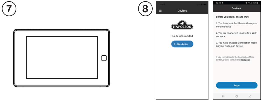
- Turn on Bluetooth on your device, select “Add Device” and accept the permissions
- Search for devices and select the device from the list.
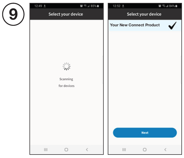
- Select your desired WiFi and connect by entering the WiFi password of your home.
- Once the appliance has been connected to the access point, it can be given a nickname for recognizability.
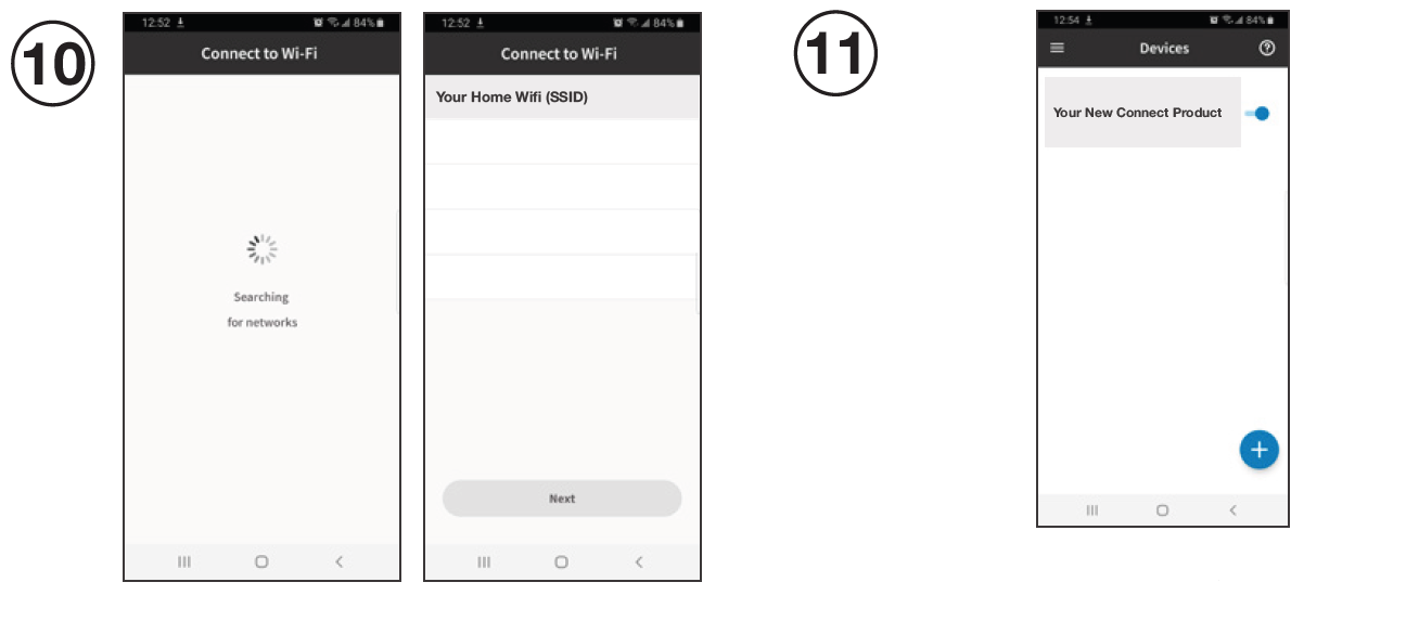
- You are now connected

 To register your EQHub Smart Thermostat and Heat Pump as a Hybrid Heating solution, please go to: https://www.napoleon.com/en/ca/heating-cooling/ product-registration-eqhub-smart-thermostat.
FAQs
What is the WiFi configuration if the thermostat fails?
- Confirm the device, mobile phone, and router are as close as possible.
- Confirm that the network is stable. Put the phone beside your device and ensure they are in the same network environment. Try to open a website to ensure the networ can be used.
- Confirm adding device is under 2.4G WiFi channel. If 2.4G and 5G WiFi use the same name, it is recommended to change one to a different name
- Confirm the entered router password is correct.
- If it still does not work, it is recommended to reset the router and try again.
What if the device is offline?
- Confirm if the thermostat is powered on.
- Confirm if the device or the network has been cut off. If so, please reconnect the network, as it may need some time to recover. Please check the status 2 minutes later.
- Confirm that the network is stable. Put the phone beside your device and ensure they are in the same network environment. Try to open a website to ensure the network can be used.
- Confirm if the home WiFi network is normal or if the WiFi name and password has been modified. If necessary, remove the device and add again.If the network is normal but the device is still offline, please check if there are too many WiFi connections.
- Try restarting the router, wait for 5 minutes, and observe the status of the device.
- If it still does not work, it is recommended to remove the device or reset the router and then add it again.
Refer to website FAQ page for more details.
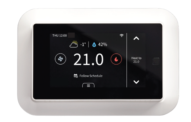
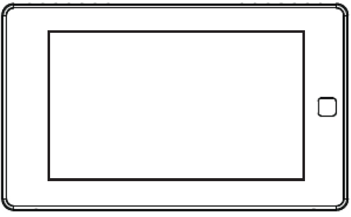
MEET YOUR THERMOSTAT
DEVICE OVERVIEW
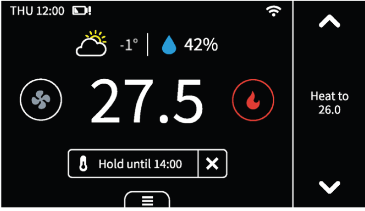
Main Page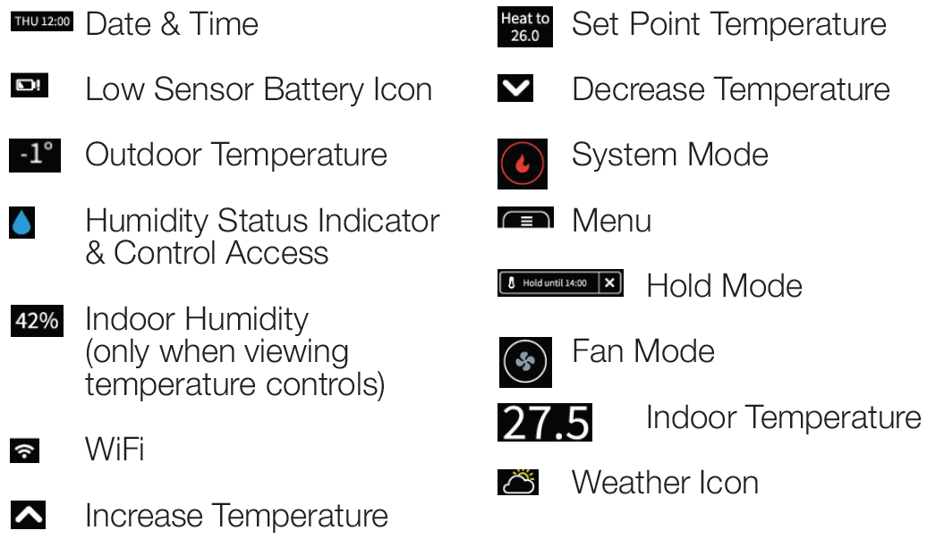
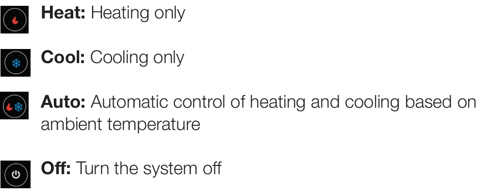
System Mode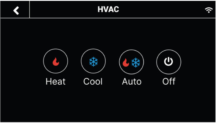
Weather
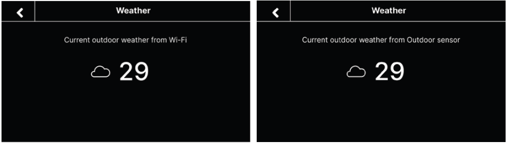
Click the weather icon on the home page to display the real time outdoor weather condition and temperature for the current day in your home location.
NOTE: The weather display screen will indicate the source of the outdoor temperature value. If the outdoor sensor is activated and in use, the thermostat will display the temperature value from the outdoor sensor. If the outdoor sensor is offline or unavailable, the thermostat will display an outdoor temperature value from the cloud.
Humidifier/Dehumidifier
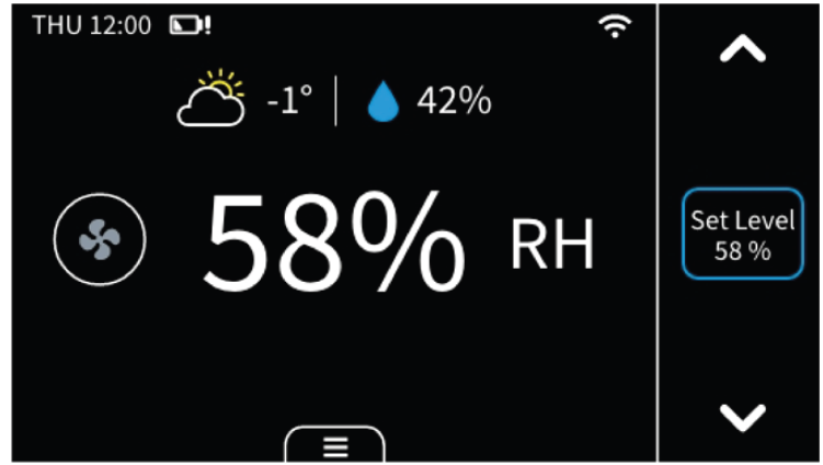
 Humidity indicator & temperature control access
- + for humidifying
 – for dehumidifying
- Tap icon to switch between humidity and temperature views
- Outdoor humidity (only when viewing humidity controls)
- Increase humidity level if humidifier is connected
- Humidity level
- Decrease humidity level if dehumidifier is connected
- Indoor humidity
Heating Options
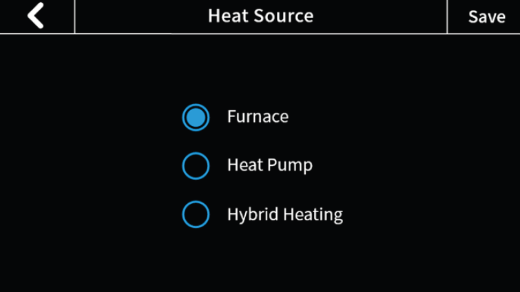
Heat Source
- Furnace
- Heat Pump
NOTE: The below settings are only applicable when the heat source selected is Heat Pump: - Min. Heat Pump Outdoor Temperature: When the outdoor temperature is below this temperature, the Heat Pump will not be used.
- Max. Heat Pump Run Time: This is the length of time the Heat Pump is allowed to run.
- Hybrid
Choose your preferred source of heating from the options in Heat Source. The thermostat will satisfy demand based on selections made. The Hybrid selection will enable the use of dual fuel switching, alternating between primary and secondary heat sources.
Hybrid Mode
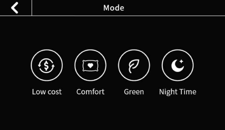
When Hybrid heating is selected in Menu > System > Heating Options > Heat Source, the heat source used by the system is controlled by the values in the corresponding modes’ switching
table. The switching tables can be accessed in Menu > Hybrid Heating.
Low Cost: Satisfy your heating demands using the lowest cost available fuel source. In this mode, the second stage HP heating is will be turned on according to the ‘Compressor Stage2 Temp Delta’ (non adjustable) and ‘Compressor Stage1 Max Runtime’ (adjustable) and second stage furnace heating will be turned on according to ‘Aux Heat Stage 1 Max Runtime’ (adjustable) and ‘AUX Heat Stage 2 Temp Delta’ (non adjustable) in Menu > Settings > Installation > Advanced setting
Comfort: Satisfy your heating demands with any available fuel source to prioritize your comfort levels, always keeping your home as close to your desired set point as possible. In this mode, the second stage HP heating is will be turned on according to the ‘Compressor Stage2 Temp Delta’ (non adjustable) and ‘Compressor Stage1 Max Runtime’ (adjustable) and second stage furnace heating will be turned on according to ‘Aux Heat Stage 1 Max Runtime’ in Menu > Settings > Installation > Advanced setting.
Green: The values in your green switching table are formulated to help in prioritizing GHG savings and reducing your carbon footprint when satisfying your heating demand. In this mode, the second stage HP heating is will be turned on according to the ‘Compressor Stage2 Temp Delta’ (non adjustable) and ‘Compressor Stage1 Max Runtime’ (adjustable) and second stage furnace heating will be turned on according to ‘Aux Heat Stage 1 Max Runtime’ (adjustable) and ‘AUX Heat Stage 2 Temp Delta’ (non adjustable) in Menu > Settings > Installation > Advanced setting.
Nighttime: Run quiet operation of your unit at night, limiting fan speed and utilizing low stage heating for aslong as possible. In this mode, second stage HP heating is controlled by values in ‘Compressor Stage2 Temp Delta’ and ‘Hybrid Max Heat Pump Runtime’ and second stage furnace heating will be turned on a cording to the ‘Aux Heat Stage 1 Max Runtime’ and ‘AUX Heat Stage 2 Temp Delta’ in Menu > Settings > Installation > Advanced setting.
Hold Mode
There are 3 hold modes you can select:
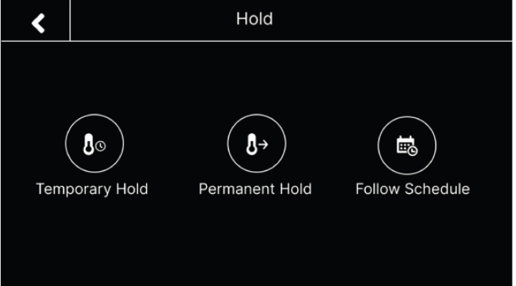
- Follow Schedule: Follow the settings of schedule to adjust the temperature, fan, or hybrid mode (if enabled). When you remove hold, the mode will turn to “Follow Schedule”.
- Permanent Hold: This will always hold the current target temperature, fan, or hybrid mode (if enabled). It will override the current schedule settings.
- Temporary Hold: Keep the current target temperature, fan, or hybrid mode (if enabled) until the next scheduled activity begins. You can select this mode manually or by adjusting the target temperature, fan, or hybrid mode (if enabled) under “Follow Schedule” mode, as it will turn to “Temporary Hold”.
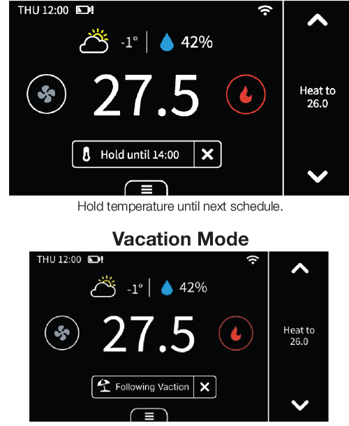
If you are away for a long time, you can set the thermostat to vacation mode in “Menu” -> “Vacation”. You can set the time of departure and return, as well as the highest and lowest temperatures during this period. The thermostat will automatically hold this temperature range.
NOTE: During this mode, you cannot manually change the target temperature. If you want to exit this mode, change the Hold mode manually or delete the vacation in menu.
MEET YOUR THERMOSTAT
Display
Here are some changes on the screen and what they mean:
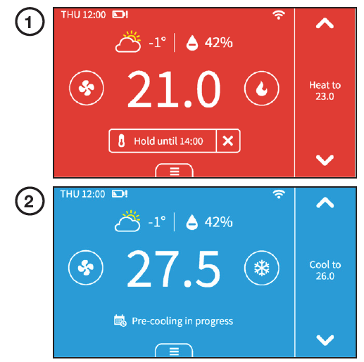
When you turn on the compressor frequently, there will be a time countdown to protect the compressor. This will occur in the following case: Heat pump: heating, cooling || Conventional: cooling You can set the time countdown in “Menu” -> “Installation” ->“Advanced” -> “Compressor Protect Time”.When the outdoor temperature is below the “Compressor Min Outdoor Temp” you set, the icon on system mode will display ! and the compressor will be turned off automatically. The thermostat is connected to the router, but the router is not connected to the network.
Unusual heating or cooling alert
When the following occurs, this prompt appears on the thermostat:
- When your thermostat is cooling, the temperature in the room does not go down for a long time, but instead, the temperature still rises.
- When your thermostat is heating, the temperature in the room does not go up for a long time, but instead, the temperature still falls.
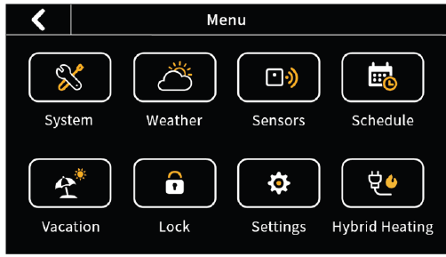
System
- HVAC: Switch system mode (Heat/Cool/Auto/Off)
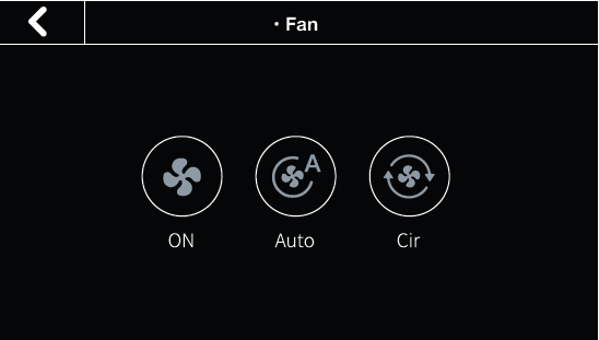
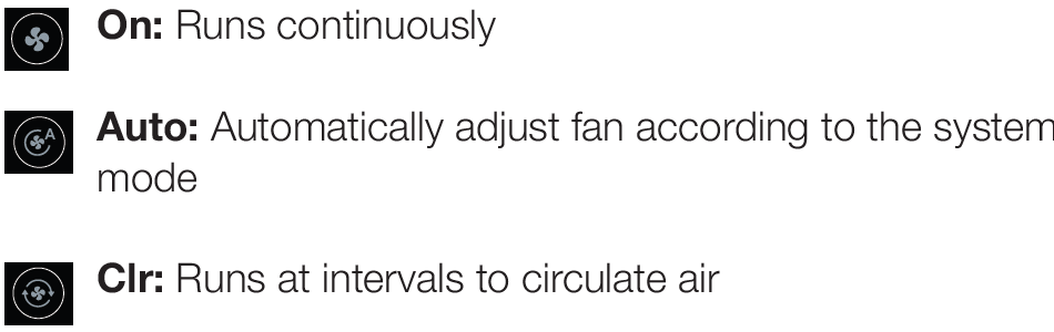
- Fan: Switch fan mode (ON/Auto/Cir)
![]() Weather
Weather
Weather conditions of the real time in your home location.
Sensors
Add multi-sensors to balance the current temperature throughout the home.
Schedule
Set schedule to change the temperature automatically.
Vacation
Set vacation to change the temperature automatically
Lock
Multi-level keypad lockout to avoid others tampering with the settings. After locking, the corresponding function is not available and the corresponding settings icon will go dim. An icon with a small lock will appear on top of the main page.
Settings
- Date & Time: Set time format.
- Fan Run Time: Set minimum fan run time in “Clr” mode during heating/cooling cycles.
- WiFi: Configure and display WiFi information.
- Smart Warm-Up: When smart warm-up is enabled, your thermostat automatically calculates when to turn on heating or cooling so your home will reach a scheduled temperature on time. This only worked in “Follow Schedule” mode.
- Device Name: Rename your device.
- Temp Unit: Celsius or Fahrenheit.
- Temp Range: Set the adjustment range of heating and cooling.
- Screen: Adjust screen brightness on active/standby/ sleep and standby time.
- T/H Correction: Adjust the accuracy of temperature and humidity to match your environment.
- Installation
Advanced Settings
- Heat/Cool Dissipation Time
This is the amount of time the fan will continue to run once the heat/cool is turned off. It will circulate any heated/cooled air remaining in the vents. - Compressor Protect Time
A timed countdown to protect the compressor from starting too frequently. - Compressor/Aux Heat Min On Time
This is the length of time the compressor or auxiliary heat is turned on during heating/cooling cycles. - Aux Heat Stage 2 Temperature Delta
When the difference between the indoor temperature and the target temperature reaches this value, the second stage is automatically turned on. - Aux Heat Stage 1 Max Routine
If the first stage fails to reach the target temperature after this time, the second stage will be automatically turned on. - Hybrid Max Heat Pump Run Time
This is the length of time the Heat Pump is allowed to run in hybrid heating mode. - Differential Temperature/Humidity
This is the allowable value from your set point before your heating, cooling, or humidity call is made.
Hybrid Heating
Set mode to low-cost, comfort, green, or night (see “Hybrid Mode” section for more details).
Equipment
Reconfigure your wiring setting on thermostat.
Equipment Test
Test whether the corresponding function of the equipment can run normally as required.
- Filter: Filter change reminder.
- Reset:
- Reset setting
Reset schedule (Reset system schedule and clear vacation.)
Reset all (Reset the thermostat to default factory setting.)
- About: Show device information.
APP OVERVIEW
Control Page
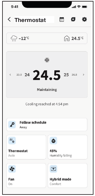
- Thermostat Mode: Displays the current system mode. Tap to switch.
- Fan Mode: Displays the current fan mode. Tap to switch.
- Hold Mode: Displays the current hold mode. Tap to switch.
- Schedule: Set a schedule for the week so that you can get the right temperature at a certain time.
- Humidity Control: Displays the current humidity level. Tap to adjust target level.
- Set Point Temperature:Increase/decrease the target temperature.
- Heating Mode: Displays heating source selection. When hybrid heating is selected, options to select hybrid modes will be displayed.
- Settings: You can edit the app settings, such as device name, heat source, temperature unit, and geofencing.
WARRANTY
NAPOLEON products are manufactured under the strict Standard of the world recognized ISO 9001 : 2015 Quality Assurance Certificate.
WSC43BA ACCESSORY WARRANTY
NAPOLEON products are designed with superior components and materials and are assembled by trained craftsmen who take great pride in their work. NAPOLEON warrants the components in your new NAPOLEON product will be free from defects in material and workmanship from the date of purchase, for a period of 3 years.
- WSC43BA Thermostat 3 Years
- WSC-IS Indoor Sensor
- WSC-OS Outdoor Sensor
- WSC-PWRM Power Modul
CONDITIONS AND LIMITATIONS
Some states and provinces do not allow limitations on how long an implied limited warranty lasts or do not allow the exclusion or limitation of incidental or consequential damages, so the limitations or exclusions may not apply to you.
- NAPOLEON warrants its products against manufacturing defects to the original purchaser only, provided that the purchase was made through an authorized NAPOLEON dealer and is subject to the following conditions and limitations:
- This factory warranty is non-transferable and may not be extended what-so-ever by any of our representatives.
- The product must be installed by a licensed, authorized HVAC technician or contractor. Installation must be done in accordance with the installation instructions included with the product and all local and national building and fire codes.
- This limited warranty does not cover damages caused by misuse, lack of maintenance, hostile environments, accident, alterations, abuse, or neglect. Discoloration to plastic parts from chemical cleaners or UV exposure is not covered by this warranty.
- This limited warranty further does not cover any scratches, dents, painted finishes, abrasive, and chemical cleaners, nor any components used in the installation of the product.
- Changes in operating environment – NAPOLEON shall not be responsible for issues caused by changes in the operating characteristics of the hardware, or for problems in the interaction of the software product with non-NAPOLEON-SOFTWARE or HARDWARE PRODUCTS.
- The Software used in this device is excluded from the warranty coverage.
- All parts replaced under the Limited Three-Year Warranty Policy are subject to a single claim.
- NAPOLEON will not be responsible for the installation, labour or any other costs or expenses related to the re-installation of a warranted part, and such expenses are not covered by this warranty.
- Notwithstanding any provision contained in this Limited Three-Year Warranty, NAPOLEON’s responsibility under this warranty is defined as above and it shall not in any event extend to any incidental, consequential, or indirect damages.
- NAPOLEON neither assumes, nor authorizes any third party to assume, on its behalf, any other liabilities with respect to the sale of this product.
- The bill of sale or copy will be required together with a serial number and a model number when making any warranty claims from NAPOLEON.
- NAPOLEON reserves the right to have its representative inspect any product or part prior to honoring any warranty claim.
- Some states and provinces do not allow limitations on how long an implied limited warranty lasts or do not allow the exclusion or limitation of incidental or consequential damages, so the limitations or exclusions may not apply to you.
FOR HOMEOWNERS FUTURE REFERENCE
- Model and Serial Number (Serial number located on back of thermostat)
- Installation Date
- Dealer Name
- Dealer’s City/Province-State/Postal-Zip Code
- Telephone/Fax
- E-mail Address
For further information about this warranty, contact Napoleon Customer Solutions Department at 866-820-8686,24 Napoleon Road, Barrie, Ontario L4M 0G8 Canada
Reference
Download Manual:
napoleon WSC43BA Touchscreen Thermostat USER GUIDE
![]()
Leave a Reply