
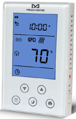
Mco-home MH4 Electrical Heating Thermostat
Introduction
MH4 is a Z-Wave Plus enabled device for indoor temperature control. It is mainly applied to control electrical heating systems, such as heating film, heating cable, heater, etc. With the floor over-heating protection and GFCI (Ground Fault Circuit Interrupter) function, this device works as a reliable indoor temperature controller. Besides its stable performance, the unique design is also an attractive feature for end users. Moreover, a built-in Z-Wave module makes it a smart device which can be operated in any Z-Wave network with other Z-Wave-certified devices .
Features
- Tempered glass panel with capacitive touch buttons
- With two sensors to detect indoor& floor temperature
- Floor overheating protection
- GFCI(leakage protection): level 5mA
- Multi-working modes to meet various user needs: Time Period(Schedule) Mode
- Comfort Mode
- Energy-saving Mode
- Vacation Mode
- Programmable schedule: 4 periods each day of 7 days; 5+2; 5+1+1
Specification
- Power supply: AC120V/AC240V, 60Hz
- Max output: 1800W at 120AC ; 3600W at 240AC
- Self-consumption: <2W
- Temp. format: ℃ /℉ ; Time format: 12h / 24h
- Z-Wave frequency: 908.42MHz, 941.42MHz or other customized
- Panel dimension: 76*120*20mm
- Vertical installation:hole pitch 82mm (American 120 box )
Safety Information
To protect yourself and others from danger and to protect the device from damage, please read the safety information before using it.
Important!
- A qualified electrician with the understanding of wiring diagrams and knowledge of electrical safety should complete installation following the instructions.
- Before installation, please confirm the real voltage complying with the device’s specification. Cut off any power supply to secure the safety of people and device.
- During installation, protect the device from any physical damage by dropping or bumping. If happens, please contact the supplier for maintenance.
- Keep the device away from acid-base and other corrosive solids, liquids, gases, to avoid damage.
- Avoid overexertion during operation, to protect device from mechanical damage.
- Read all instructions and documentation and save for future reference.
Installation & Wiring
Location:
Thermostat is suggested to be installed indoor, a place with around 41/2 to 5 feet height above the floor where represents the average room temperature. It should be away from direct sunlight, any cover, or any heat source, to avoid false signal for temperature control.
CAUTION: Cut off power supply at circuit breaker or fuse before installation to avoid fire, shock or death!
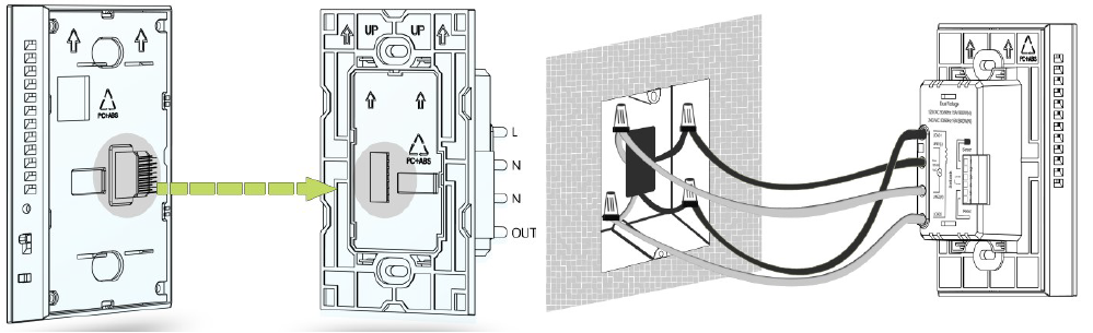
- Step 1: Separate the device with a flat-head screwdriver into two parts: the display panel and the bottom case.
- Step 2: Insert all wires into the right terminals and tighten screws. Wiring diagram is shown below.
- Step 3: Push the bottom case into the junction box and secure it with two screws, and then mount the touch panel back.
- Step 4: Confirm the device is well mounted, power on and it is ready to operate.
Wiring diagram:
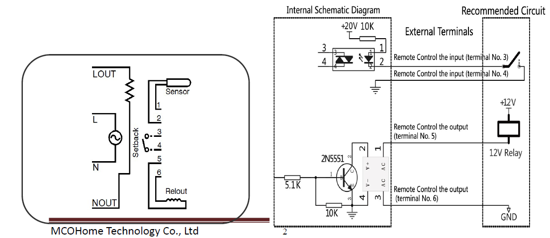
Note:
- Setback (terminals 3&4):the input terminal controlled by remote; one terminal connect to the internal power source with a 10K resistor, the other terminal connect to the internal ground wire.
- Relout (terminals 5&6):the output terminal controlled by remote; inside circuit is a OC output, it can drive a relay that below 24V directly.The maximum drivable current is 30MA. The internal circuit is shown as above
Operation
On/Off operation
- ON:When it displays OFF, slide up the ON/OFF button to turn it on. Local time, the corresponding temperature, working mode and output status will be displayed on the screen.
- OFF:In normal working interface, slide down the ON/OFF button to turn it off. It will display OFF on the screen and all outputs will be closed.
GFCI Test
- Enter into GFCI test:In the normal working interface, when the electrical heating is working, press GFCI button, the icon of GFCI will be displayed on the screen, and the output of electrical heating is closed, indicator light is on .
- Exit from GFCI test: slide the ON/OFF button to turn it off and then turn it on, the device will back to the normal working interface, the electrical heating begin to output and the icon of GFCI disappeared.
Note: There is a electric leakage protector inside the thermostat, it’s used to protect the operator avoid electric shock when the system is damaged. After installed the device, test this function to make sure the proper operation of it.
- To make sure the thermostat is in the mode of heating. Please adjust the set point temporarily when it necessary.
- When you press GFCI button, the icon of GFCI will be displayed on the screen, and the output of electrical heating is closed, indicator light is on ,otherwise, you should turn down the thermostat and replace it.
Local Time Setting
In shutdown mode, long press![]() button to enter into the Time settings interface. The blinking icon is the current modifiable item, press
button to enter into the Time settings interface. The blinking icon is the current modifiable item, press![]() or
or![]() button to set the values; press
button to set the values; press![]() button to switch the setting value. When finish the setting, press
button to switch the setting value. When finish the setting, press![]() button as confirm or delay for 10s without any operation to save all the values and return to the normal working interface automatically. During setting, press
button as confirm or delay for 10s without any operation to save all the values and return to the normal working interface automatically. During setting, press![]() button at any time, it can return to the normal working interface directly and the values will be saved.
button at any time, it can return to the normal working interface directly and the values will be saved.
Working Mode Setting
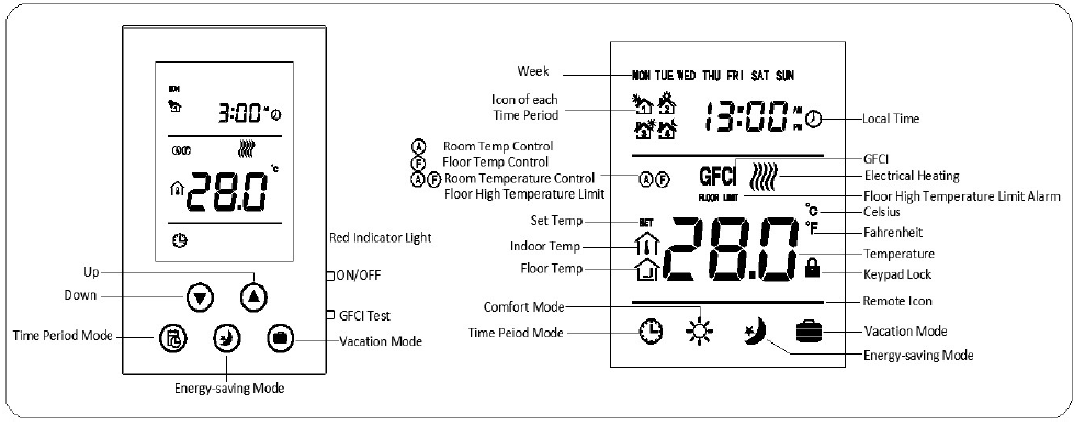
- Icon
 displays on the screen indicates it is in Time Period Mode
 - Icon
 displays on the screen indicates it is in Manual Mode
 - Icon
 displays on the screen indicates it is in Energy-saving Mode
 - Icon
 displays on the screen indicates it is in Vacation Mode
When the corresponding icon of working mode is blinking, press![]() button to confirm or delay for 10s without any operation to save the values and return to the normal working interface automatically.
button to confirm or delay for 10s without any operation to save the values and return to the normal working interface automatically.
Temperature Setting
In any mode, press![]() or
or![]() button to enter into the Set Temp settings interface of the corresponding mode. The “Set Temp” is blinking.
button to enter into the Set Temp settings interface of the corresponding mode. The “Set Temp” is blinking.
- Press
 button to decrease the temperature, press
 button to increase the temperature.
 - After enter into the interface of Set Temp settings, long press or button to decrease/ increase the temperature continuously.
- After finish the settings, press
 button to confirm or delay for 10s without any operation to save the values and return to the normal working interface automatically.
Check the Temperature
In the normal working interface, press![]() and
and![]() buttons simultaneously, the displayed temperature will be switched between the room temp and floor temp
buttons simultaneously, the displayed temperature will be switched between the room temp and floor temp
Keypad Lock
In the normal working interface, press![]() and
and![]() buttons simultaneously to lock the keypad, at the same time the icon
buttons simultaneously to lock the keypad, at the same time the icon![]() will be displayed on the screen. When the keypad is locked, you cannot do any operation of it. When the icon of Keypad Lock
will be displayed on the screen. When the keypad is locked, you cannot do any operation of it. When the icon of Keypad Lock![]() displays on the screen, press
displays on the screen, press![]() and
and![]() buttons simultaneously to unlock the keypad, and the icon
buttons simultaneously to unlock the keypad, and the icon![]() will disappear from the screen, and the keypad is back to its normal state.
will disappear from the screen, and the keypad is back to its normal state.
Time Period Setting
In the normal working interface, long press![]() button to enter into the Time Period settings interface. First, the “HOUR”of the first period is blinking.
button to enter into the Time Period settings interface. First, the “HOUR”of the first period is blinking.
- The blinking item is the adaptable item, press or button to change the values.
- In the setting interface, press
 button to switch the weekday, the switch sequence is Monday→Tuesday→Wednesday→Thursday→Friday→Saturday→Sunday→Exit.
 - In the setting interface, press
 button to switch the item among HOUR, MINUTE, Set Temp, and Time Period of each day, press button continuously, the time period will be switched from the 1st period to the 4th period.
 - During setting, press
 button to return to normal working interface directly, and the changed values will be save.
The default setting is as follow:
| Week\Periods | Period 1 | Period 2 | Period 3 | Period 4 | ||||
| Mon~Fri | 5:00 | 28℃(82
℉) |
7:00 | 24℃(75
℉) |
17:00 | 28℃(82
℉) |
22:00 | 24℃(75
℉) |
| Sat~Sun | 5:00 | 28℃(82
℉) |
9:00 | 24℃(75
℉) |
17:00 | 28℃(82
℉) |
22:00 | 24℃(75
℉) |
Output Control
Floor Temperature Control Mode
F Floor Temperature Control, A : Room Temperature Control, AF : Room Temperature Control with floor high-temperature protection. When the icon F displays on the screen indicates the system is in Floor Temperature Control Mode, and the icon![]() will be displayed beside the temperature value, it indicates the current detected temperature is the floor temperature. When the detected indoor temperature ≤ the set temperature for -1.5℃,electrical heating will be turned on, and the icon
will be displayed beside the temperature value, it indicates the current detected temperature is the floor temperature. When the detected indoor temperature ≤ the set temperature for -1.5℃,electrical heating will be turned on, and the icon![]() will be displayed on the screen; when the detected indoor temperature≥ the set temperature, electrical heating will be turned off, the icon
will be displayed on the screen; when the detected indoor temperature≥ the set temperature, electrical heating will be turned off, the icon![]() disappeared.
disappeared.
Room Temperature Control Mode
When the icon A displays on the screen indicates the system is in Room Temperature Control Mode, when the icon![]() displays on the screen, it indicates the current temperature that displayed on the screen is the indoor temperature. When the detected indoor temperature ≤ the set temperature for 2.5℃, electrical heating will be turned on, and the icon
displays on the screen, it indicates the current temperature that displayed on the screen is the indoor temperature. When the detected indoor temperature ≤ the set temperature for 2.5℃, electrical heating will be turned on, and the icon![]() will be displayed on the screen; when the detected indoor temperature≥ the set temperature, electrical heating will be turned off, and the icon
will be displayed on the screen; when the detected indoor temperature≥ the set temperature, electrical heating will be turned off, and the icon![]() will be disappeared from the screen
will be disappeared from the screen
Room Temperature Control, Floor High Temperature Limit Mode
If the icon AF displays on the screen, it indicates the system is in the Room Temperature Control ,Floor High Temperature Limit Mode, when the icon![]() displays on the screen, itindicates the current temperature that displayed on the screen is the indoor temperature. When the detected indoor temperature ≤ the set temperature for-2.5℃, electrical heating will be turned on,and the icon
displays on the screen, itindicates the current temperature that displayed on the screen is the indoor temperature. When the detected indoor temperature ≤ the set temperature for-2.5℃, electrical heating will be turned on,and the icon![]() will be displayed on the screen; when the detected indoor temperature ≥ settemperature, electrical heating will be turned off, and the icon
will be displayed on the screen; when the detected indoor temperature ≥ settemperature, electrical heating will be turned off, and the icon![]() will be disappeared. Press
will be disappeared. Press![]() and
and![]() buttons simultaneously, the displayed temperature will switch to the floor temperature, and the icon
buttons simultaneously, the displayed temperature will switch to the floor temperature, and the icon![]() will display beside the temperature. When the temperature is higher than 45℃ (113℉), the output will be closed, and then the icon FLOOR LIMIT will be displayed on the screen to avoid overheating the floor. When the floor temperature reduced to 40℃(104℉), electrical heating will be turned on again, and the icon FLOOR LIMIT will be disappeared.
will display beside the temperature. When the temperature is higher than 45℃ (113℉), the output will be closed, and then the icon FLOOR LIMIT will be displayed on the screen to avoid overheating the floor. When the floor temperature reduced to 40℃(104℉), electrical heating will be turned on again, and the icon FLOOR LIMIT will be disappeared.
Remote Control Output
When the remote control signal input, the icon of remote is blinking; when the detected indoor temperature ≤the set temperature for -2.5, electrical heating will be turned on, and the icon![]() will be displayed on the screen; meanwhile, the Relout start output signals, when the detected indoor temperature≥ the set temperature, electrical heating will be turned off, and the icon
will be displayed on the screen; meanwhile, the Relout start output signals, when the detected indoor temperature≥ the set temperature, electrical heating will be turned off, and the icon![]() will be disappeared, meanwhile, the Relout close turn off output signal. The setting default temperature is 16.5℃(61℉) on the remote control mode.
will be disappeared, meanwhile, the Relout close turn off output signal. The setting default temperature is 16.5℃(61℉) on the remote control mode.
Notes: Remote signal control output has the highest priority.
Sensor Failure
When sensor failed to work, the icon EEE will display on the screen. The output will be closed.
Cumulative Time of the valve
In shutdown interface, long press![]() button, the cumulative time of the valve will be displayed on the screen. The cumulative time will reset and restarted when press
button, the cumulative time of the valve will be displayed on the screen. The cumulative time will reset and restarted when press![]() and
and![]() buttons simultaneously.(Unit:min)
buttons simultaneously.(Unit:min)
Temperature Unit Switching
In shutdown interface, long press![]() and
and![]() can switch the temperature unit settings
can switch the temperature unit settings
Z-Wave Operation
Including & Excluding of Z-Wave network
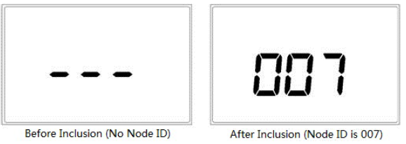
In normal working interface, press & hold![]() to enter interface for inclusion or exclusion of Z-Wave network. Before device included into network, “- – -” will display on the screen. Then press once
to enter interface for inclusion or exclusion of Z-Wave network. Before device included into network, “- – -” will display on the screen. Then press once![]() , device will enter learning mode to get a node ID. If inclusion is success, a node ID will display on the screen in a few seconds. A node ID can always inform us whether the device is in the network or not.
, device will enter learning mode to get a node ID. If inclusion is success, a node ID will display on the screen in a few seconds. A node ID can always inform us whether the device is in the network or not.
Note: Follow the same steps to exclude the device from the network.
After inclusion, turn off the device and then turn it on. Now the device is ready to be operated by controller/ gateway in Z-Wave network.
Association Group
Thermostat supports 1 association group. A gateway is suggested to associate with this group. Then if any changes happen, such as: temperature, working mode, etc., the thermostat will report to this associated device (gateway).
Command Class supported by the device:
- COMMAND_CLASS_ZWAVEPLUS_INFO,
- COMMAND_CLASS_VERSION,
- COMMAND_CLASS_MANUFACTURER_SPECIFIC,
- COMMAND_CLASS_DEVICE_RESET_LOCALLY,
- COMMAND_CLASS_ASSOCIATION,
- COMMAND_CLASS_ASSOCIATION_GRP_INFO,
- COMMAND_CLASS_POWERLEVEL,
- COMMAND_CLASS_BASIC,
- COMMAND_CLASS_FIRMWARE_UPDATE_MD_V2,
- COMMAND_CLASS_CONFIGURATION,
- COMMAND_CLASS_SENSOR_MULTILEVEL_V5,
- COMMAND_CLASS_THERMOSTAT_SETPOINT,
- COMMAND_CLASS_THERMOSTAT_MODE,
- COMMAND_CLASS_THERMOSTAT_OPERATING_STATE,
- COMMAND_CLASS_TIME,
- COMMAND_CLASS_TIME_PARAMETERS
Note: Basic CC is used to control energy saving mode and comfort mode:
- Basic Set (Value = 0x00) = Set Energy Saving Mode
- Basic Set (Value = 0xFF) = Set Comfort Mode
- Basic Get = Get Report
- Basic Report (Value = 0x00) = Report Energy Saving Mode
- Basic Report (Value = 0xFF) = Report Comfort Mode
The other values besides the two above will be ignored.
Note:
This device supports 4 kinds of modes in Z-Wave: Off mode; Heating mode (Manual); Energy Saving heating mode (Auto) ; Away heating mode (Vacation). Users can set these 4 modes via COMMAND_CLASS_THERMOSTAT_MODE. And COMMAND_CLASS_BASIC can switch among Heating mode & Energy saving heating mode. COMMAND_CLASS_THERMOSTAT_SETPOINT can be used to set the heating temperature threshold value in Heating mode or Energy saving heating mode. Downloaded from
Parameters Settings
| Add | Function | Byte | Options | Default | Remark |
|
1 |
Upload temperature format automatically |
1 |
0x00Celsius 0x01Fahrenheit
0x02Follow the main display |
0x02 |
|
|
2 |
Upload temperature value automatically |
1 |
0x00 OFF
0x01 Upload the temperature difference value only 0x02 Timing upload mode only 0x03 Upload the difference value+timing upload mode |
0x03 |
|
|
3 |
Upload temperature difference |
2 |
Base on 0.1℃unit, 0x0005
by default, 5*0.1℃=0.5℃, 0x0003~0x03E8 |
0x0005 |
0.5℃ |
|
4 |
Upload time interval regularly |
2 |
Base on 1s unit, it suggest to be set above 30s
0x000A~0xFFFF |
0x001E |
30S |
|
FF |
Factory setting |
1 |
0x55 Restore the factory setting(write only) |
Parameters setting restore to default value, association
groups deleted |
FCC Warning
Changes or modifications not expressly approved by the party responsible for compliance could void the user’s authority to operate the equipment
FCC Interference Statement (Part 15.105 (b)) (USA only)
This equipment has been tested and found to comply with the limits for a Class B digital device, pursuant to Part 15 of the FCC Rules. These limits are designed to provide reasonable protection against harmful interference in a residential installation. This equipment generates, uses, and can radiate radio frequency energy and, if not installed and used in accordance with the instructions, may cause harmful interference to radio communications. However, there is no guarantee that interference will not occur in a particular installation. If this equipment does cause harmful interference to radio or television reception, which can be determined by turning the equipment off and on, the user is encouraged to try to correct the interference by one of the following measures:
- Reorient or relocate the receiving antenna.
- Increase the separation between the equipment and receiver.
- Connect the equipment into an outlet on a circuit different from that to which the receiver is connected.
- Consult the dealer or an experienced radio/TV technician for help
Configuration of User Parameters (Hidden Menu)
In shutdown interface, press![]() and
and![]() buttons simultaneously to enter into the parameters setting interface, then input password 1234 using “Up” button and “Down” button, press
buttons simultaneously to enter into the parameters setting interface, then input password 1234 using “Up” button and “Down” button, press![]() to switch, then press “Confirm” button to enter into the setting interface. Following is the value of each parameter:
to switch, then press “Confirm” button to enter into the setting interface. Following is the value of each parameter:
|
NO. |
Parameter |
Default Value |
Setting Range |
Note |
||||
|
P1 |
High Temp Protection |
45℃(113℉) |
OF/45 ~
(113-203℉) |
95℃ | OF: Turn off the floor high temp protection | |||
| P2 | Room Temperature Calibration | 0(00) | -9.5~9.5℃(-16~16℉) | |||||
| P3 | Temperature Backlash Value | 2℃(4℉) | 0.5~10℃(1-18℉) | |||||
|
P4 |
Key Volume Level |
3 |
OF/1~9 |
OF:OFF
1 ~ 9 : Length Volume |
of |
the |
Key |
|
|
P5 |
Backlight Brightness |
NO |
NO/ OF |
NO:Always on
OF:Energy Saving of Backlight |
||||
|
P6 |
Control Mode |
A-F |
A-F/Air/Flo |
Air:Ambient Room Temperature Control Mode Flo:Floor Temperature Control Mode
A/F:Room Temperature Control, with Floor High Temperature Limit Mode |
||||
|
P7 |
Time System |
24 |
12/24 |
12:12-hour time system
24:24-hour time system |
||||
| P8 | Floor Temperature Calibration | 0(00) | -9.5~9.5℃(-16~16℉) | |||||
|
P9 |
Backlash Value of Floor Temp
Control |
1.5℃(03℉) |
0.5~10℃(01~18℉) |
|||||
|
P10 |
Backlash Value of Floor
Protection Temp |
5.0℃(09℉) |
0.5~10℃(1-18℉) |
|||||
|
P11 |
Temp Setting of Remote Control Mode |
16.5℃(62℉) |
5~37℃(41-99℉) |
|||||
|
P12 |
Factory Reset |
53 |
0~99 |
Set it to 55 and then press S3 to
confirm to set it to Factory Reset. |
||||
| P13 | Heating temp increasing speed | 5 | 0-99 | |
|
P14 |
Celsius/Fahrenheit |
OC |
OC/OF |
OC:Celsius OF:Fahrenheit
( After modify settings, to restore the factory settings.) |
Troubleshooting
| Problem | Solution |
|
Thermostat functions but no heat from the system |
1. Check wiring instructions and wire identification 2. If the GFCI is tripped, reset the thermostat with the side switch 3. Check the resistance of the floor warming system. Refer to the cable manufacturer installation manual |
|
No display |
Check wiring connection on the back of the unit |
|
GFCI is tripped |
1. Check wiring connections 2. Reset thermostat by switching off then back on 3. Check resistance of the floor warming system. Refer to the cable manufacturer installation manual |
|
Heat occurs at wrong time |
Check the current time and schedule are properly set at AM or PM |
|
Error EEE |
Check floor sensor resistance. Change if out of range |
1-year Limited Warranty
MCOHome warrants this product to be free from defects in material and workmanship under normal and proper use for one year from purchase date of the original purchaser. MCOHome will, at its option, either repair or replace any part of its products that prove defective by reason of improperworkmanship or materials. THIS LIMITED WARRANTY DOES NOT COVER ANY DAMAGE TO THIS PRODUCT THAT RESULTS FROM IMPROPER INSTALLATION, ACCIDENT, ABUSE, MISUSE, NATURAL DISASTER, INSUFFICIENT OR EXCESSIVE ELECTRICAL SUPPLY, ABNORMAL MECHANICAL OR ENVIRONMENTAL CONDITIONS, OR ANY UNAUTHORIZED DISASSEMBLY, REPAIR OR MODIFICATION. This limited warranty shall not apply if:
- the product was not used in accordance with any accompanying instructions, or
- the product was not used for its intended function.
This limited warranty also does not apply to any product on which the original identification information has been altered, obliterated or removed, that has not been handled or packaged correctly, that has been sold as second-hand or that has been resold contrary to Country and other applicable export regulations.
Reference
Download Manual:
Mco-home MH4 Electrical Heating Thermostat Instruction MANUAL
Mco-home MH4 Electrical Heating Thermostat Instruction MANUAL
Leave a Reply