
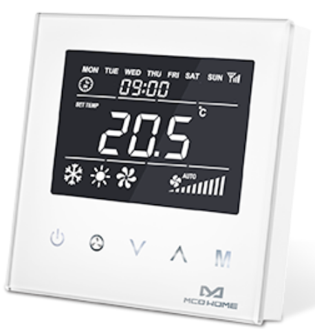
Mco-home MH8-FC4-EU Fan Coil Z-WAVE Thermostat
Introduction
MCOHome Fan Coil Thermostat is a Z-Wave-enabled device for indoor temperature control. It is mainly applied to a 4-pipe Fan coil system. It can read room temperature and local time, and automatically control fan speed based on the temperature difference. The device is of high reliability and practicability. This product can be included and operated in any Z-Wave network with other Z-Wave-certified devices from any other manufacturers.
Features:
- Capacitive touch buttons
- Tempered glass panel, PC alloy enclosure
- Precise temperature calibration function
- Non-volatile Memory, working state saved even power failure
- Intelligent on/off control of 3-speed fan, electric (ball) valve or air-valve
- Easily steel frame back plate installation
Specification
- Power Supply:AC85V~260V, 50/60HZ
- Resistive Load: ≤3A
- Self-Consumption :< 1W
- Temperature Sensor: NTC 15K
- Display Accuracy: 0.1 ℃
- Working Environment:0~55℃; <95% RH(Non-condensation)
- Temperature Setting:5~35 ℃(Adjustable)
- Dimension:86* 86*42mm
- Hole Pitch:60-65mm(86 Standard junction box)
- Z-Wave Frequency: 868.42MHz (EU)
Safety Information
To protect yourself and others from danger and to protect the device from damage, please read the safety information before using it.
Important!
- A qualified electrician with the understanding of wiring diagrams and knowledge of electrical safety should complete installation following the instructions
- Before installation, please confirm the real voltage complying with the device’s specification.
- Cut off any power supply to secure the safety of people and device.
- During installation, protect the device from any physical damage by dropping or bumping. If happens, please contact the supplier for maintenance.
- Keep the device away from acid-base and other corrosive solids, liquids, gases, to avoid damage.
- Avoid overexertion during operation, to protect device from mechanical damage.
- Read all instructions and documentation and save for future reference
Installation & Wiring
Location:
Thermostat is suggested to be installed indoor, a place with around 1.5m height above the floor where represents the average room temperature. It should be away from direct sunlight, any cover, or any heat source, to avoid false signal for temperature control.
CAUTION: Cut off power supply at circuit breaker or fuse before installation to avoid fire, shock or death!
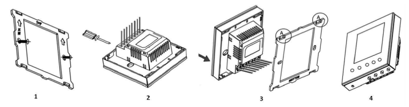
- Step 1: Remove the steel frame from the device, and secure it onto the junction box with two screws.
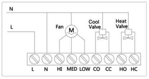
- Step 2: Insert all wires into the right terminals and tighten screws. The wiring diagram is shown below.
- Step 3: Attach the wired device on “A” points of the steel frame as shown first, and then push the whole device into junction box.
- Step 4: Confirm the device is well mounted, power on and it is ready to operate
Note:
- CO–Cool Valve Open CC–Cool Valve Close
- HO–Heat Valve Open HC–Heat Valve Close
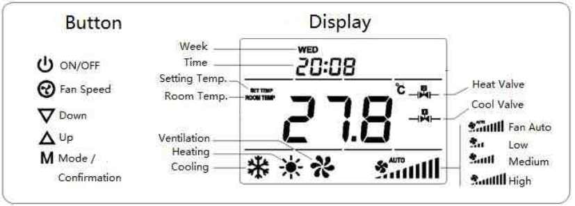
Operation
On/Off Setting
When power on, thermostat will display “OFF” press![]() to enter working interface. When normal working, press
to enter working interface. When normal working, press![]() to turn off the device, “OFF” displays and all outputs are off.
to turn off the device, “OFF” displays and all outputs are off.
Local Time Setting
Press & hold “M” to enter local time setting. Touch “M” to switch among Week, Hour & Minute, and then press![]() or
or![]() to set the parameters of flashing item. Press “M” ,or wait for 15s to save the value and return to display.
to set the parameters of flashing item. Press “M” ,or wait for 15s to save the value and return to display.
Working Mode Setting
Touch “M” to enter working mode setting, the current mode flashing. Press![]() or
or![]() to switch among Cooling
to switch among Cooling![]() , Heating
, Heating![]() & Ventilation
& Ventilation![]() mode, then press “M”, or wait for 15s to confirm the choice.
mode, then press “M”, or wait for 15s to confirm the choice.
Temperature setting
Touch![]() or
or![]() to set local temperature value. Hold the buttons can set continuously. Press “M” , or wait for 15s to save and return to room temperature display.
to set local temperature value. Hold the buttons can set continuously. Press “M” , or wait for 15s to save and return to room temperature display.
Fan Speed setting
In normal display, press![]() to switch among the fan speed :“ Low, Medium, High, Auto” ; Then press “M”, or wait for 15s to confirm the choice.
to switch among the fan speed :“ Low, Medium, High, Auto” ; Then press “M”, or wait for 15s to confirm the choice.
Note: In Ventilation mode, no Auto speed choice.
Fan Manually control
If fan speed is manually set , the device still auto control the fan in such situation:
Cooling Mode:
- Room temperature ≤ setting temperature, valve closes and fan stops;
- Room temperature ≥ setting temperature +1 ℃, valve and fan opens.
Heating Mode:
- Room temperature ≥ setting temperature, valve closes and fan stops;
- Room temperature ≤ setting temperature -1 ℃, valve and fan opens.
Fan Automation
|
Cooling Mode |
a. Room temperature ≤ setting temperature, valve closes automatically, fan stops;
b. Room temperature ≥ setting temperature +1 ℃, fan turned on in low speed; c. Room temperature ≥ setting temperature +2 ℃, fan turned on in medium speed; d. Room temperature ≥ setting temperature +3 ℃, fan turned on in high speed; |
|
Heating Mode |
a. Room temperature ≥ setting temperature, valve closes automatically, fan stops;
b. Room temperature ≤ setting temperature -1 ℃, fan turned on in low speed; c. Room temperature ≤ setting temperature -2 ℃, fan turned on in medium speed; d. Room temperature ≤ setting temperature -3 ℃, fan turned on in high speed; |
Note:
- Fan will operate only if the valve opens.
- In cooling mode, device controls cool valve; In heating mode, device controls heat valve.
Parameter Setting
Power Failure Memory
Under the shutdown state, press & hold![]() will enter interface for power failure memory selection,“PAGE”displays. Press
will enter interface for power failure memory selection,“PAGE”displays. Press![]() or
or ![]() to change setting value, then press “M” to confirm and return.
to change setting value, then press “M” to confirm and return.
After power failure:
- 000 (default) indicates device will be in shutdown state (“OFF”) when power on again;
- 001 indicates device will be in working interface when power on again;
- 002 indicates device will stay the status before power failure when power on again.
Temp. Calibration/ Temp. Setting Range
Under the shutdown state, press & hold![]() will enter interface for temperature calibration, “-ERR”displays. The calibration range is among -5.0 ~ +5.0 ℃. Press
will enter interface for temperature calibration, “-ERR”displays. The calibration range is among -5.0 ~ +5.0 ℃. Press![]() or
or![]() to change setting value, then press “M” save and enter interface for temp.
to change setting value, then press “M” save and enter interface for temp.
Range setting (0~99℃):
- “-HI-” displays, the default value is 35℃. Press
 or
or can set the value;
 - Press “M” again, “-LO-”displays, the default value is 5℃. Press or can set the value;
- Then press “M” to confirm and return to “OFF”.
Under the shutdown state, press & hold “M” will enter interface for screen brightness selection (LED), Press or can choose: (press “M” to confirm the choice and enter into next setting) 111 indicates the screen will always be full bright when power on; 000 (default) indicates without button operation for a long time (15 seconds), the screen will be half bright automatically.
Press “M” again will enter interface for Fan continuously work choice:
- 000 (default) indicates device will shutdown fan and valve if room temp. Reaches setting temp.;
- 001 indicates device will shutdown valve only if room temp. Reaches setting temp. The fan will continuously work in low speed.
Press “M” again will enter interface for Key-touch volume (BEEP) setting:
- Off
- Low(default)
- High
Z-Wave Operation
Including & Excluding of Z-Wave network
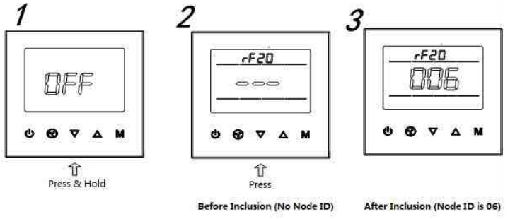
Under the shutdown state, press & hold![]() to enter interface for inclusion or exclusion of Z-Wave network. Before device included into network, “- – -” will display on the screen. Then press
to enter interface for inclusion or exclusion of Z-Wave network. Before device included into network, “- – -” will display on the screen. Then press![]() once, device will enter learning mode to get a node ID. If inclusion is success, a node ID will display on the screen in a few seconds. A node ID can always inform us whether the device is in the network or not.
once, device will enter learning mode to get a node ID. If inclusion is success, a node ID will display on the screen in a few seconds. A node ID can always inform us whether the device is in the network or not.
Note: Follow the same steps to exclude the device from the network.
After inclusion, turn off the device and then turn it on. Now the device is ready to be operated by controller/ gateway in Z-Wave network.
Association Group
Thermostat supports 1 association group. A gateway is suggested to associate with this group. Then if any changes happen, such as: temperature, working mode, fan state etc., the thermostat will report to this associated device (gateway). When the detected temperature change ≥0.5℃, device will send unsolicited report to the gateway.
Command Class supported by the device:
- COMMAND_CLASS_BASIC;
- COMMAND_CLASS_THERMOSTAT_SETPOINT;
- COMMAND_CLASS_THERMOSTAT_MODE;
- COMMAND_CLASS_THERMOSTAT_FAN_MODE;
- COMMAND_CLASS_THERMOSTAT_OPERATING_STATE;
- COMMAND_CLASS_SENSOR_MULTILEVEL;
- COMMAND_CLASS_ASSOCIATION;
- COMMAND_CLASS_VERSION;
- COMMAND_CLASS_MANUFACTURER_SPECIFIC
1-year Limited Warranty
MCOHome warrants this product to be free from defects in material and workmanship under normal and proper use for one year from purchase date of the original purchaser. MCOHome will, at its option, either repair or replace any part of its products that prove defective by reason of improper workmanship or materials. THIS LIMITED WARRANTY DOES NOT COVER ANY DAMAGE TO THIS PRODUCT THAT RESULTS FROM IMPROPER INSTALLATION, ACCIDENT, ABUSE, MISUSE, NATURAL DISASTER, INSUFFICIENT OR EXCESSIVE ELECTRICAL SUPPLY, ABNORMAL MECHANICAL OR ENVIRONMENTAL CONDITIONS, OR ANY UNAUTHORIZED DISASSEMBLY, REPAIR OR MODIFICATION. This limited warranty shall not apply if:
- the product was not used in accordance with any accompanying instructions, or
- the product was not used for its intended function.
This limited warranty also does not apply to any product on which the original identification information has been altered, obliterated or removed, that has not been handled or packaged correctly, that has been sold as second-hand or that has been resold contrary to Country and other applicable export regulations
Reference
Download Manual:
Mco-home MH8-FC4-EU Fan Coil Z-WAVE Thermostat User MANUAL
Leave a Reply