
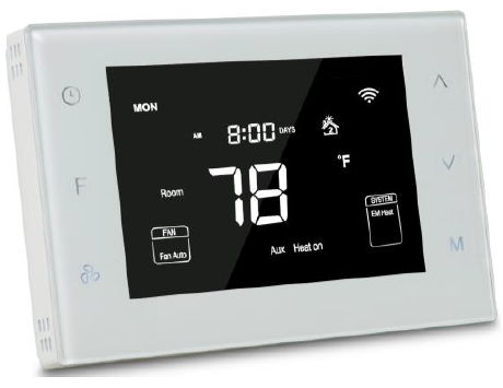
Mco-home MH6-HP Programmable Thermostat
Introduction
MH6 HP programmable thermostat is a Z Wave enabled device for indoor temperature control. It is mainly applied to heat pump system for heating/cool ing, with 3 modes easily switchable: Schedule, Hold and Holiday. The device is of high reliability and practicability, and it can support up to 3H/2C system. This product can be included and operated in any Z Wave network with other Z Wave certified device s from any other manufacturers.
Features:
- Elegant design with 4.3” LCD display
- Individual programming Schedule s : 7 days*4 time periods
- Tempered glass panel with Capacitive touch buttons
- NTC thermistor
- Built in Z Wave module
Specification
- Power supply AC24V, 50 /60 Hz
- Power dissipation 2W
- Dimension: 136*94*26mm
- Output: 1A (Resistant load)
- Temperature range: 41ºF 99ºF (5 37 ℃℃)
- Display accuracy: ±0.5 ºC
- Wiring: Terminals
- Installation dimension: 60mm / 82mm (hole pitch)
Safety Information
To protect yourself and others from danger and to protect the devi ce from damage, please read the safety information before using it.
Important!
- A qualified electrician with the understanding of wiring diagrams and knowledge of electrical safety should complete installation following the instructions
- Before installatio n , please confirm the real voltage complying with the device s specification. Cut off any power supply to secure the safety of people and device.
- During installation, protect the device from any physical damage by dropping or bumping. I f happens , please c ontact the supplier for maintenance.
- Keep the device away from acid base and other corrosive solids, liquids, gases, to avoid damage
Avoid overexertion during operation, to protect device from mechanical damage - Read all instructions and documentation an d save for future reference
Installation & Wiring
CAUTION:
Cut off power supply at circuit breaker or fuse before installation to avoid fire, shock or death!

Wiring diagram

Wiring Terminals
| Terminals | Explanation | Remark |
| RC | Cooling power (two transformers) | Joined with R by jumper (one transformer) |
| R | Heating power (two transformers) | Joined with RC by jumper (one transformer) |
| W (O/B) | Heat output | Changeover valve output (heat pump) |
| Y | Cool output | Compressor output (heat pump) |
| G | Fan output | |
| C | 24VAC common | Connect only when AC power |
| Y2 | Cool output 2 | 2nd stage compressor output (heat pump) |
| W2(AUX) | Heat output 2 | Auxiliary heat output (heat pump) |
Controlling Type
| No. | Type | Terminals | Wiring | Compressor delay |
| 0.0 | 1H/1C (conventional) | R、G、W、Y |
Diagram conventional systems |
none |
| 1.0 | 1H/2C (conventional) | R、G、W、Y、Y2 | none | |
| 2.0 | 2H/2C (conventional) | R、G、W、Y、W2、Y2 | none | |
| 3.0 | 2H/1C (conventional) | R、G、W、Y、W2 | none | |
| 4.0 | 1H/1C (heat pump) | R、G、O/B、Y |
Diagram heat pump systems |
1 min (default) |
| 5.0 | 2H/1C (heat pump) | R、G、O/B、Y、AUX | 1 min (default) | |
| 6.0 | 2H/2C (heat pump) | R、G、O/B、Y、Y2 | 1 min (default) | |
| 7.0 | 3H/2C (heat pump) | R、G、O/B、Y、AUX、Y2 | 1 min (default) |
Note: Before operation, pls set the controlling type based on the real situation by referring to the Secret Menu (last page) and following the instruction.

Operation
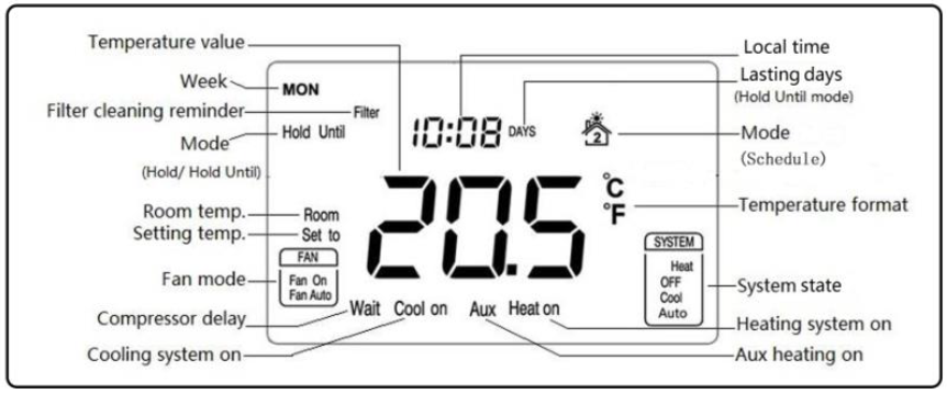
Temperature format( ℃/ ℉)
In normal display interface, press![]() & F button synchronically for at least 3 sec to switch between ℃ and Not available in Hold or Hold Until Mode.
& F button synchronically for at least 3 sec to switch between ℃ and Not available in Hold or Hold Until Mode.
Local time setting
Press & hold![]() for 3 sec to enter into the interface for the local time setting. First, 00-year flashes (0~99 indicates 2000~2099 year), press
for 3 sec to enter into the interface for the local time setting. First, 00-year flashes (0~99 indicates 2000~2099 year), press![]() or
or![]() to modify the values, then press
to modify the values, then press![]() to switch to 01 months, month value flashes, press
to switch to 01 months, month value flashes, press![]() or
or![]() to modify the values, then press to
to modify the values, then press to![]() switch to 02 day, day value flashes, press or to
switch to 02 day, day value flashes, press or to![]() modify the values, then press to
modify the values, then press to![]() switch to 03 hour, hour value flashes, press
switch to 03 hour, hour value flashes, press![]() or
or![]() to modify the values, then press to switch to 04 minutes, minute value flashes, press or to modify the values. Continually press , it will sw itch among Year Month Day Hour Minute. Press
to modify the values, then press to switch to 04 minutes, minute value flashes, press or to modify the values. Continually press , it will sw itch among Year Month Day Hour Minute. Press![]() to save the status then back to the temperature setting interface, set to ” display s and temperature value flashing , then press
to save the status then back to the temperature setting interface, set to ” display s and temperature value flashing , then press![]() or
or![]() to modify the value, press F or wait for the delay time end, return back to nor mal display. Local time can not be set in Hold Until mode
to modify the value, press F or wait for the delay time end, return back to nor mal display. Local time can not be set in Hold Until mode
System state setting
In normal display interface, press M slowly to switch among Heat , OFF , Cool & Auto ””. After the state change, set to ” display s and temperature value flash for 5 sec . User s can choose to change the value for temperature setting. If not, press F twice to save the change and return to normal display. (Changed value only valid in this current Schedule, and will lose if Schedule, system state changes or power off)
- OFF : In this state, Heating, Cooling and Fan will all forced close. Displays keep on.
- Auto : In this state, a constant temperature will be kept. Device will activate/ stop heating/cooling system automatically according to the setting and room temperature.
Conventional system
Heat
- Room temp. Setting temp. 1 ℃℃, Heat on displays and 1 st stage heating system is on;
- Room temp. Setting temp. 2 ℃℃, Heat on AUX display and 2 nd stage heating system is on; (not available for 1 stage heat
- Room temp. Setting temp., heating system stops and Heat on disappears from screen.
Note: 2nd heat stops and AUX disappears when temp. difference is less than 1
Cool
- Room temp S etting temp ..+1 ℃, Cool on displays and 1 st stage cooling system is on;
- Room temp S etting temp ..+2 ℃, Cool on stays and 2 nd stage cooling system is on ; (not available for 1 stage cool
- Room temp S etting temp ., cooling system stops and Cool on disappears from screen.
Note: 2 nd cool stops when temp. difference is less than 1 ℃℃.
Heat pump system
- Heat (Changeover valve keep
- Room temp. Setting temp. 1 ℃℃, Heat on displays and 1 st stage heating system is on;
- Room temp. Setting temp. 2 ℃℃, Heat on stays and 2 nd stage he ating system is on;
- Room temp. Setting temp. 3 ℃℃, Heat on AUX display and Aux heating system is on;
- Room temp. Setting temp., heating system stops and Heat on disappears from screen.
Note: Aux heat stops and AUX disappears when temp. difference is less than 2 ℃℃. 2 nd heat stops when temp. difference is less than 1
Cool (Changeover valve keep
- Room temp Setting temp ..+1 ℃, Cool on displays and 1 st stage cooling system is on;
- Room temp Setting temp ..+2 ℃, Cool on stays and 2 nd stage cooling system is on;
- Room temp Setting temp ., cooling system stops and Cool on disappears from screen.
Note:
2 nd cool stops when temp. difference is less than 1
Compressor protection
After an operation of heating/cooling system, there is a 1 min compressor off time to protect compressor. Wait will display on the screen if next operation is activated within the 1 min period.
Fan mode setting
Press![]() to switch among Fan on & Fan Auto
to switch among Fan on & Fan Auto
- Fan o n Fan is always on.
- Fan Auto Fan runs auto matically only when heating/cooling system is on
(If system is in OFF state, the fan will always off)
Mode setting
Press F to switch among Schedule , Hold & Hold Until modes.
Schedule
Any icon from![]() stands for one time period, and ther e are 4 periods can be set in one day.
stands for one time period, and ther e are 4 periods can be set in one day.
- Under the time setting mode, press to enter into time setting interface, the time parameter of cooling or heating mode can be set. Press
 then switch among 7 days 5+2 days a whole week: [ MON TUE WED THU →FRI→SAT→ MON TUE WED THU FRI SAT SUN MON TUE WED THU FRI SAT SUN ]. When setting the parameters, press F to exit to the modify interface, then get back to the temperature setting interface.
- Press flashes then press
 or
or to change the time (changes in 15 minutes at a time);
 - After completed the time setting, Press to switch to the temperature setting, setting temperature flash and press or to modify the setting temperature.
- After fin ished the above steps, press to switch to 2 st period of Monday and repeat item 1 and 2 steps, then complete 4 periods of Monday setting. Press to save and enter schedule setting for the following day.
- Press
- Under the time setting mode, when the time is set to –, the current schedule will be disabled, and it will follow the previous time setting until enter into the next schedule. If 4 period of a day is —-, then it will run the last schedule by The below table is the time parameter setting in different modes: (Factory default)
| Periods | Time | Parameters | |
| Heating | Cooling/ Auto | ||
| 1 | 06:00 | 21.0℃ | 25.5℃ |
| 2 | 08:00 | 16.5℃ | 29.5℃ |
| 3 | 18:00 | 21.0℃ | 25.5℃ |
| 4 | 22:00 | 16.5℃ | 28.0℃ |
Notes: Cooling and Auto mode use the same setting schedule.
Hold
This mode comes after Schedule by pressing F . In this mode, device will keep a constant temperature until next change.
- Hold & ” set to display and temperature value flashing. Press or can change the value, and press F to save the setting;
- Press M can set syst em state;
- Press
 can set fan mode.
Hold Until (Holiday)
This mode comes after Hold by pressing F again . In this mode, device will follow the setting temperature and lasting days when users are out for a holiday. And then back to follow Schedules after the holiday.
- Hold Until & ” set to display and temperature value flashing. Press or can change the value, and press F to save the setting. Then days value flashing, users can choose from 1 365 days by pressing or ;
- Press M can set system state;
- Press can set fan mode.
Override temperature setting
During any Schedule period, press![]() or
or![]() can enter an interface for temperature setting. Press
can enter an interface for temperature setting. Press![]() or
or![]() to change setting temperature, and press F to save the change. The changed setting only valid in th e current Schedule period, device will follow the original schedule in next period.
to change setting temperature, and press F to save the change. The changed setting only valid in th e current Schedule period, device will follow the original schedule in next period.
Filter cleaning reminder
Filter ” will flash on the screen to remind users of cleaning furnace filter, and 90 calendar days are the default timing . In Schedule mode, to press![]() for 3 sec, filter ” will disappear from screen.
for 3 sec, filter ” will disappear from screen.
Sensor error
If FF flashes at temperature display area, it means the temp. sensor is out of work(short circuit or broken circuit), all the outputs will be forced close, and only back to normal work unt il the sensor circuit is normal again.
Resorting factory settings
Press![]() & M for 3 sec, “set to” displays and temperature value flashing, then press F to restore factory settings.
& M for 3 sec, “set to” displays and temperature value flashing, then press F to restore factory settings.
Z Wave operation
Including & Excluding of Z Wave network
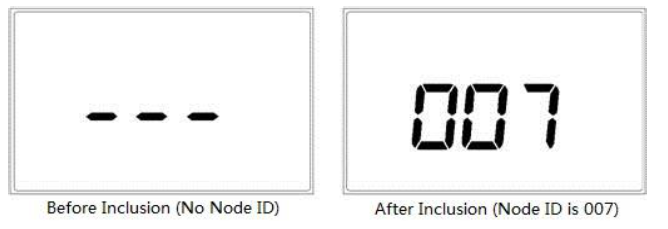
In normal displa y, press & hold![]() to enter interface for inclusion or exclusion of Z Wave network. Before device included into network, “ –” will display on the screen. Then press
to enter interface for inclusion or exclusion of Z Wave network. Before device included into network, “ –” will display on the screen. Then press![]() once, device will enter learning mode to get a node ID. If inclusion is success, a node ID will display on the screen in a few seconds. A node ID can always inform us whether the device is in the network or not. After inclusion, press & hold
once, device will enter learning mode to get a node ID. If inclusion is success, a node ID will display on the screen in a few seconds. A node ID can always inform us whether the device is in the network or not. After inclusion, press & hold![]() will return to normal display. Now the device is ready to be operated by controller/ gateway in Z Wave network.
will return to normal display. Now the device is ready to be operated by controller/ gateway in Z Wave network.
Note: Follow the same steps to exclude the device from the network.
Association Group
Thermostat supports 1 association group. A gateway is suggested to associate with this group. Then if any changes happen, such as: temperature, wo rking mode, fan state etc., the thermostat will report to this associated device (gateway).
Command Class supported by the device:
- COMMAND_CLASS_BASIC;
- COMMAND_CLASS_THERMOSTAT_SETPOINT;
- COMMAND_CLASS_THERMOSTAT_MODE;
- COMMAND_CLASS_THERMO
- STAT_FAN_MODE;
- COMMAND_CLASS_THERMOSTAT_OPERATING_STATE;
- COMMAND_CLASS_SENSOR_MULTILEVEL;
- COMMAND_CLASS_ASSOCIATION;
- COMMAND_CLASS_VERSION;
- COMMAND_CLASS_MANUFACTURER_SPECIFIC
Parameters Settings:
| Add | Function | Byte | Options | Default | Remark |
|
1 |
Upload temperature format automatically |
1 |
0x00 Celsius 0x01 Fahrenheit
0x02 Follow the main display |
0x02 |
|
|
2 |
Upload temperature and humidity automatically |
1 |
0x00 OFF
0x01 Upload the difference value only 0x02 Timing upload mode only 0x03 Upload the difference+timing upload mode |
0x03 |
|
|
3 |
Upload temperature difference |
2 |
Base on 0.1℃unit, 0x0005 by
default, 5*0.1℃=0.5℃, 0x0003~0x03E8 |
0x0005 |
0.5℃ |
|
4 |
Upload time interval
regularly |
2 |
Base on 1s unit, it suggest to be
set above 30s 0x000A~0xFFFF |
0x001E |
30S |
|
5 |
Upload humidity difference |
1 |
When the detection humidity value differ with the last percentage value, uploading
activated 0x02~0xFF |
0x03 |
3% |
|
FF |
Factory setting |
1 |
0x55 Restore the factory setting(write only) |
Parameters setting back to default value, association groups
deleted |
1 year Limited Warranty
MCOHome warrants this product to be free from defects in material and workmanship under normal and proper use for on e year from purchase date of the original purchaser. MCOHome will, at its option, either repair or replace any part of its products that prove defective by reason of improper workmanship or materials. THIS LIMITED WARRANTY DOE S NOT COVER ANY DAMA GE TO THIS PRODUCT THAT RESULT S FROM IMPROPER INSTALLATIO N, ACCIDENT, ABUSE, MISUSE, NATURAL DISA STER, INSUFFICIENT O R EXCESSIVE ELECTRICAL SUPPLY, ABNORMAL ME CHANICAL OR ENVIRONM ENTAL CONDITIONS, OR ANY UNAUTHORIZED DISASSEMBLY, REPAIR OR MODIFICATION. This limited warranty shall not apply if:
- the product was not used in accordance with any accompanying instructions, or
- the product was not used for its intended function.
This limited warranty also does not apply to any product on which the original identifi cation information has been altered, obliterated or removed, that has not been handled or packaged correctly, that has been sold as second hand or that has been resold contrary to Country and other applicable export regulations.
Secret Menu
In Schedule Mode, long press![]() and
and![]() synchronically can enter into secret menu, and the code is 5138. Press
synchronically can enter into secret menu, and the code is 5138. Press![]() or
or![]() can change the setting, and press M can save and switch to the following item.
can change the setting, and press M can save and switch to the following item.
Table 1
| Item | Explain | Range | Default | Remark |
| 0 | Controlling Type | 0.0-7.0 | 0.0 | See table “Controlling
Type” |
| 1 | (1H/1C)Differential | 0.5℃/1℃/1.5℃/2℃ | 1.0℃ | |
| 2 | Temperature calibration | -10℃~10℃ | 0.0℃ | |
| 3 | Temperature setting upper limit | 0-99.5℃ | 37.0℃ | Upper limit value > lower limit value |
| 4 | Temperature setting lower limit | 0-99.5℃ | 5.0℃ | |
| 5 | Filter change reminder | 1 /2 /30 /60 /90 /120 days | 090 days | |
| 6 | Clock format | 12 /24 hours | 24.0 | |
| 7 | Compressor protection delay | 0~10min | 1.0min | |
| 8 | Back light setting | ON/OF | OF | ON back-lit always on OF back-lit half bright
when no operation |
| 9 | Temperature format | ℃/℉ | ℃ | |
| Restore factory setting | OF/ON | OF | ON for restoring |
FCC STATEMENT
This device complies with part 15 of the FCC Rules. Operation is subject to the following two conditions: (1) This device may not cause harmful interference, and (2) this device must accept any interference received, including interference that may cause undesired operation. Changes or modifications not expressly approved by the party responsible for compliance could void the user’s authority to operate the equipment. This equipment has been tested and found to comply with the limits for a Class B digital device, pursuant to part 15 of the FCC Rules. These limits are designed to provide reasonable protection against harmful interference in a residential installation. This equipment generates uses and can radiate radio frequency energy and, if not installed and used in accordance with the instructions, may cause harmful interference to radio communications. However, there is no guarantee that interference will not occur in a particular installation. If this equipment does cause harmful interference to radio or television reception, which can be determined by turning the equipment off and on, the user is encouraged to try to correct the interference by one or more of the following measures:
- Reorient or relocate the receiving antenna.
- Increase the separation between the equipment and receiver.
- Connect the equipment into an outlet on a circuit different from that to which the receiver is connected.
- Consult the dealer or an experienced radio/TV technician for help.
Reference
Download Manual:
Mco-home MH6-HP Programmable Thermostat User MANUAL
Mco-home MH6-HP Programmable Thermostat User MANUAL
Leave a Reply