
Leviton RC-2000 Digital Wireless Thermostat
Instruction
WARNINGS AND CAUTIONS
- Read and understand all instructions. Follow all warnings and instructions marked on the product.
- Do not use this product near water – e.g., near a tub, wash basin, kitchen sink or laundry tub, in a wet basement, or near a swimming pool.
- Never push objects of any kind into this product through openings, as they may touch dangerous voltages.
- Never install communications wiring or components during a lightning storm.
- Never install communications components in wet locations unless the components are designed specifically for use in wet locations.
- Never touch uninsulated wires or terminals unless the wiring has been disconnected at the network interface.
- Use caution when installing or modifying communications wiring or components.
DESCRIPTION
The RC-2000 is a precision digital thermostat designed for 24 VAC heating and cooling systems. The RC-2000 will support the following systems:
- Single Stage Heat/Cool Conventional
- Two Stage Conventional (2 Stage Heat / 2 Stage Cool)
- Heat Pump and Geothermal Heat Pump (2 Stage Heat / 1 Stage Cool)
- Speed Heat Pump and Geothermal Two Speed Heat Pump (3 Stage Heat / 2 Stage Cool)
- Dual Fuel Heat Pump and Geothermal Dual Fuel Heat Pump
- Humidifier and Dehumidifier Control
The RC-2000 has the capability of being controlled both locally and by remote control. It offers programmability, stand-alone operation, and robust, optically isolated communications with automation systems, utility control systems, and personal computers.
- Electrical rating: 24 V; 2 A; 50/60 Hz
- Maximum current: 2 A on any circuit, 3 A total
The following requirements must be observed for installation in Europe: CE
- This equipment must be installed in accordance with National wiring rules for the country in which it is installed.
- All product labels, instructions and markings relating to safety must be translated to a language, which is acceptable in the country in which this equipment is to be installed.
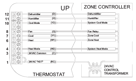
CONFIGURATION
- The “System Type” for this thermostat must be set to “Zone Control” under “System Options”.
- The two additional outputs (W2 and Y2) are use with zoned heating and cooling systems.
- The W2 and Y2 terminals control the mode of operation (heating or cooling) of the zone control panel.
- The zone control panel will recognize calls for heat (W) from the individual zones when the W2 terminal is energized, and calls for cool (Y) when the Y1 terminal is energized.
- Neither W2 nor Y2 is energized when the mode is set to “OFF”. Therefore, the RC-2000 can act as a Master to set the operating mode of the entire system.
POWER UP
- Double check wiring, be sure that there are no stray wires or wire strands at the connections.
- Connect power to the transformer and system. The display will show the current thermostat settings.
Press [FAN] and select “On”. The fan should come on. - Press [FAN] and select “Auto”. The fan should go off.
- Set the Mode to “Heat”. Raise the desired heat setting above the current temperature.
- Ensure that the heating unit comes on.
- Set the mode to “Off”.
- Ensure that the heating unit goes off.
- Set the Mode to “Cool”.
- Lower the desired cool setting below the current temperature.
- Ensure that the cooling unit comes on. Set the mode to “Off”.
- Ensure that the cooling unit goes off.
INSTALLATION
Before installing this thermostat:
- Read all of the Installation Instructions carefully.
- Read the Owner’s Manual carefully.
- Ensure that this product is suitable for your application.
- Ensure that wiring complies with all codes and ordinances.
- Disconnect power to the control transformer to prevent electrical shock and damage to equipment.
- Select an appropriate location to ensure an accurate temperature reading.
Location
When replacing an existing thermostat, install the RC-2000 in the same location. If the existing location doesn’t meet the following criteria, choose a new location to mount the RC-2000. When choosing a location for the thermostat:
- Ensure that the thermostat is mounted 5 feet above the floor and is at least 2 feet from an outdoor wall.
- Ensure that the thermostat is located in an area where there is adequate air circulation.
- Do not mount in the path of direct sunlight or of radiant heat generated by appliances.
- Do not mount behind an outdoor wall, near a fireplace, or in the path of any air ducts.
Removing an existing thermostat
- Disconnect the power to the control transformer.
- Remove the cover to the existing thermostat.
- Disconnect the wires going to each terminal on the thermostat. Label each wire with the letter or number at the terminal.
- Remove the existing plate or base from the wall.
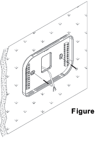
MOUNTING
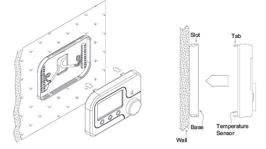
When mounting the RC-2000, grasp the thermostat by the sides, avoiding the keys, and unsnap the base from the face. Holding the base to the wall so that the word “UP” is upright and facing you:
- Mark the two mounting holes on the wall using a pencil.
- Drill a hole using a 3/16” bit at each mounting hole marking.
- Install the two wall anchors supplied.
- Slide the system wires through the opening in the base.
- Mount the base to the wall using the two #6 x 1/2” self- tapping screws supplied
CONFIGURATION
- The “System Type” for this thermostat must be set to “Conventional” under “System Options”.
- In the default configuration, this thermostat does not turn the fan on with a call for heat.
- If the furnace does not turn the fan on with a call for heat, the thermostat must be configured to do so under “System Options”.
- The “Cool Stages” and “Heat Stages” settings must be configured under “Stage Settings”.
POWER UP
- Double check wiring, be sure that there are no stray wires or wire strands at the connections.
- Connect power to the transformer and system. The display will show the current thermostat settings.
- Press [FAN] and select “On”. The fan should come on.
- Press [FAN] and select “Auto”. The fan should go off.
- Press [HOLD] and select “On” to override Energy Efficient Control.
- Set the Mode to “Heat”. Raise the desired heat setting 1 degree above the current temperature.
- Ensure that Stage 1 heat comes on.
- After a few minutes, raise the desired heat setting 3 degrees above the current temperature.
- Stage 2 heat should come on. Set the mode to “Off”. Ensure that the heating unit goes off.
- Set the Mode to “Cool”. Lower the desired cool setting 1 degree below the current temperature.
- Ensure that Stage 1 cool comes on. After a few minutes, lower the desired cool setting 3
degrees below the current temperature. Stage 2 cool should come on. - Set the mode to “Off”.
- Ensure that the cooling unit goes off.
- Press [HOLD] and select “Off” to enable Energy Efficient Control.
- Connect each wire to the terminal strip(s) on the thermostat base per the wiring diagram for your system application –
- Form the thermostat wiring so that the cable lies flat between the terminal strip(s) and the center of the base
- If a remote system or temperature sensor is being used with the thermostat, connect the remote system or temperature sensor wiring per the diagram for the application
- Upon completion of wiring the thermostat, push all excess wiring into the hole in the wall.
- Plug the hole with the supplied insulating foam to ensure an accurate temperature reading by the thermostat.
- Align the tabs of the thermostat face with the slots of the thermostat base.
- Gently push the thermostat face into the thermostat base locking it into place
About Heat Pump Systems
- Terminal 5 (O) is energized for cooling
- Terminal 6 (B) is energized for heating
- In most applications, the reversing valve is energized for cooling and should be connected to the “O” terminal.
- If the heat pump requires the reversing valve to be energized for heating, connect the reversing valve to the “B” terminal.
- With a call for Stage 2 on a two speed heat pump, both compressor outputs Y1 and Y2 are energized.
- When 2 stages of cooling and 2 stages of heating are configured for a heat pump, Stage 2 is considered high speed on the heat pump and not auxiliary heat.
- If auxiliary heat (or emergency heat) in needed, configure 3 stages of heating on the heat pump.
- To temporarily disable Energy Efficient Control and heat as quickly as possible, press [HOLD] and select
- “On”. The RC-2000 will use the Auxiliary Heat as needed to reach the heat setting.
- Terminal 9 (L) is used to indicate a fault with the heat pump compressor.
- When there is a compressor fault, the display will flash red and the “Heat Pump Fault” error message is shown.
- The Emergency Heat Relay (E Terminal) and outdoor thermostats (usually accessories to a heat pump), are not used.
- The RC-2000 automatically controls auxiliary heat efficiently.
- If the heat pump is equipped with an outdoor thermostat, it should be removed from the auxiliary heat circuit.
About Dual Fuel Heat Pump Systems
A dual fuel heat pump typically has a gas furnace combined with a heat pump. The gas furnace is used as auxiliary heat unless the outdoor temperature is very low, in which case it is used as the primary heat source.
- When used with dual fuel heat pumps, the RC-2000 requires a method for obtaining the outdoor temperature.
- A temperature sensor can be physically connected to the “Remote Temp. Sensor” terminals on the thermostat or the RC-2000 can obtain the outdoor temperature from a remote system.
- If the RC-2000 can not obtain the outdoor temperature, the heat pump compressor will not operate and the thermostat will only call for the auxiliary heat until the problem is resolved. When this occurs, the display will flash red and the “Problem With Outdoor Temperature Sensor. Some Heat Stages May Be
- Disabled” error message is displayed. After the error has been acknowledged, “Outdoor Sensor Fault” will be displayed in the Message Bar until the problem is resolved.
Balance Setpoint Limits:
- If the outdoor temperature is above the “Upper Balance Setpoint” (45°F by default), the heat pump is used exclusively.
- If the outdoor temperature falls below the “Upper Balance Setpoint” but is above the “Lower Balance Setpoint” (35°F by default) and if the heat pump is unable to heat at a rate of 5 degrees per hour or better, the heat pump will turn off and auxiliary heat will be used until the call for heat has been satisfied.
- If the outdoor temperature falls below the “Lower Balance Setpoint”, the heat pump will turn off and the auxiliary heat will be used until the call for heat has been satisfied.
- The Balance Setpoint Limits can be adjusted according to the manufacturer’s specifications under “Balance Setpoint” – See Installation Settings.
- When the RC-2000 makes a call for auxiliary heat, the heat pump compressor is turned off and the auxiliary heat is used exclusively.
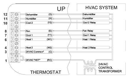
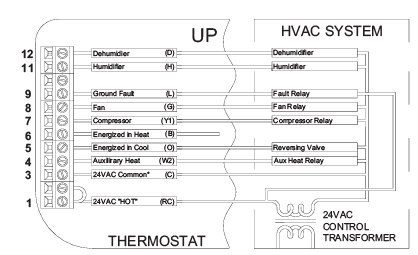
TYPICAL WIRING DIAGRAMS
- Do not short gas valve, fan, heat relay, or cool relay…even momentarily.
- Do not attempt to hook up to live circuits.
- An accidental connection to a component on the thermostat circuit board could cause damage to the thermostat.
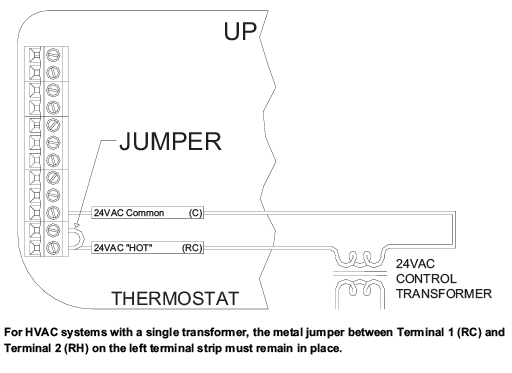
- For HVAC systems with a single transformer, the metal jumper between Terminal 1 (RC) and
- Terminal 2 (RH) on the left terminal strip must remain in place.
Important Notes:
- For HVAC systems with a single transformer for heating and cooling, the metal jumper between Terminal 1 (RC) and Terminal 2 (RH) on the left terminal strip must remain in place – See Figure 4.
- From the factory, the RC-2000 is configured to control a single stage conventional HVAC system.
- If the HVAC system is a heat pump, dual fuel heat pump, or if the thermostat is connected to a zone control system that requires a sub-base, before operating the thermostat, the “System
- Type” settings under “System Options” must be configured
- If the HVAC system is a two-stage conventional or two-speed heat pump, before operating the thermostat (making a call for heat or cool), the “Cool Stages” and “Heat Stages” settings under “Stage Settings” must be configured
CONFIGURATION
- The “System Type” for this thermostat must be set to “Heat Pump” under “System Options”.
- The “System Type” for this thermostat must be set to “Dual Fuel Heat Pump” for a dual fuel system (Terminal “W2” is connected to the “W” or “W1” on the furnace).
POWER UP
- Double check wiring, be sure that there are no stray wires or wire strands at the connections.
- Connect power to the transformer and system. The display will show all of the thermostat settings.
- Press [FAN] and select “On”. The fan should come on.
- Press [FAN] and select “Auto”. The fan should go off.
- Press [HOLD] and select “On” to override Energy Efficient Control.
- Set the Mode to “Heat”. Raise the desired heat setting 1 degree above the current temperature. Ensure that the heat pump comes on, in heating mode. After a few minutes, raise the desired heat setting 3 degrees above the current temperature. Auxiliary heat should come on. After a few minutes, set the mode to “EM Heat”. The heat pump should stop but the auxiliary heat should remain on. Set the mode to “Off”. Ensure that both the heat pump and auxiliary heat go off.
- Set the Mode to “Cool”. Lower the desired cool setting below the current temperature. Ensure that the heat pump comes on, in cooling mode. Set the mode to “Off”. Ensure that the cooling unit goes off.
- Press [HOLD] and select “Off” to enable Energy Efficient Control. When configured as a conventional thermostat, by default this thermostat does not turn the fan on with a call for heat. If the furnace requires the thermostat to turn the fan on with a call for heat, configure the “System Mode” to “Fan On With Heat” under “System Options”.
- A conventional thermostat can be configured for automatic changeover heat/cool, manual changeover heat/cool, heat only, or cool only thermostat.
- Refer to the “Configuration” steps under the wiring diagram for the respective HVAC system type.
- If the thermostat or HVAC system does not perform as stated in the “Power Up” steps under the wiring diagram for the respective HVAC system, recheck all wiring – See Troubleshooting Tips.
- For HVAC systems with separate heating and cooling transformers, the metal jumper between Terminal 1 (RC) and Terminal 2 (RH) on the left terminal strip must be removed – See Figure
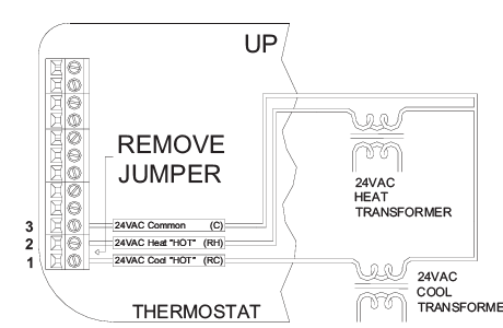
Figure 5 – Connections for heat and cool transformers – applies to all systems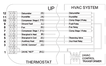
- The “System Type” for this thermostat must be set to “Heat Pump” under “System Options”.
- The “Cool Stages” and “Heat Stages” settings must be configured under “Stage Settings”.
POWER UP
- Double check wiring, be sure that there are no stray wires or wire strands at the connections.
- Connect power to the transformer and system. The display will show the current thermostat settings.
- Press [FAN] and select “On”. The fan should come on.
- Press [FAN] and select “Auto”. The fan should go off.
- Set the Mode to “Heat”. Raise the desired heat setting 1 degree above the current temperature. Ensure that the heat pump comes on, in heating mode. Press [HOLD] and select “On” to override Energy Efficient Control. Stage 2 heat should come on.
- Raise the desired heat setting 3 degrees above the current temperature. Auxiliary heat should come on.
- After a few minutes, set the mode to “EM Heat”. Both stages of the heat pump should stop but the auxiliary heat should remain on. Set the mode to “Off”. Ensure that the auxiliary heat goes off.
- Press [HOLD] and select “Off” to enable Energy Efficient Control. Set the Mode to “Cool”. Lower the desired cool setting 1 degree below the current temperature. Ensure that the heat pump comes on, in cooling mode. Press [HOLD] and select “On”. Stage 2 cool should come on.
- Set the mode to “Off”. Ensure that both stages of the cooling unit go off.
- Press [HOLD] and select “Off” to enable Energy Efficient Control.
From the factory, the RC-2000 is configured as a single stage conventional heat/cool thermostat. In the default configuration, this thermostat does not turn the fan on with a call for heat. If the furnace does not turn the fan on with a call for heat, the thermostat must be configured to do so under “System Options”. POWER UP
- Double check wiring, be sure that there are no stray wires or wire strands at the connections.
- Connect power to the transformer and system. The display will show the current thermostat settings.
- Press [FAN] and select “On”. The fan should come on.
- Press [FAN] and select “Auto”. The fan should go off.
- Set the Mode to “Heat”. Raise the desired heat setting above the current temperature.
- Ensure that the heating unit comes on. Set the mode to “Off”
- Ensure that the heating unit goes off.
- Set the Mode to “Cool”. Lower the desired cool setting below the current temperature.
- Ensure that the cooling unit comes on. Set the mode to “Off”
- Ensure that the cooling unit goes off.
- The RC-2000 thermostat is designed to work with most single-state conventional 4-wire HVAC systems (without a transformer common).
However, if the RC-2000 “resets” when calling for heat or cool, or if the heat, cool, or fan relay cannot supply 15mA to power the thermostat without the relay activating, the transformer common wire or the Leviton Thermostat Power Supply Module (Part Number: 30A00-1) is required.
REMOTE SYSTEM WIRING DIAGRAMS
This thermostat has been preprogrammed with energy saving program schedules. When used with a remote system, it is recommended that the Program Mode be configured as “None” or “Occupancy”. This will disable the internal program schedules.
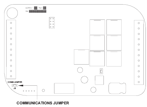
SETTING THE COMMUNICATIONS JUMPER
This thermostat comes from the factory with the communications jumper (J8) labeled “COMM JUMPER” on the thermostat printed circuit board installed – See Figure 11.
- When connecting to an Leviton Home Control system or remote switch, this jumper must be installed.
- When connecting to a PC or other device with a serial port, this jumper must be removed.
Leviton HOME CONTROL SYSTEMS
The thermostat can be connected to an Leviton Home Control system. The controller can send commands to the thermostat to change mode, cool setting, heat setting, status of fan and hold, and other items. Run a 3 (or 4) conductor wire from the Leviton system to the thermostat location. All thermostats on an Leviton Home Control system are connected to Ground, Zone +16, and Output 8 – 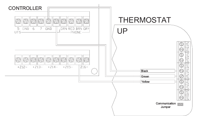
Notes:
- Additional thermostats are connected in parallel. They may be connected in home-run or daisy cLevitonn configuration.
- When connecting to an Leviton Home Control System, the communications jumper (J8) labeled “COMM JUMPER” on the thermostat printed circuit board must be in place.
| Heat Minimum On | The number of minutes the thermostat forces the heat to remain on before turning off. Raising this number will increase the total time the heating system is on (saving energy), but may allow the temperature to drift
farther from the setpoint (decreasing comfort). When combined with Heat Minimum Off, cycles per hours can be obtained by using the following calculation: 60 / (Heat Minimum On + Heat Minimum off). The default time is 6 minutes. |
|
Heat Minimum Off |
The number of minutes the thermostat forces the heat to remain off before starting again. Raising this number will increase the total time that the heating system is off (saving energy), but may allow the temperature to
drift farther from the setpoint (decreasing comfort). When combined with Heat Minimum On, cycles per hours can be obtained by using the following calculation: 60 / (Heat Minimum On + Heat Minimum off). The default time is 6 minutes. |
- All thermostats on an OmniLT controller are connected to the GRN (Green), BLK (Black), and YEL (Yellow) terminals under the section marked “TSTAT”.
| Cool Stages | The number of cool stages the HVAC system can support. The default setting is 1. |
| Heat Stages | The number of heat stages the HVAC system can support. Auxiliary heat is included in this number for heat pumps. The default setting is 1. |
EEC Control
The EEC Settings are used to configure Energy Efficient Control, 2nd Stage Differential, and Auxiliary Heat Differential. Not all of these features apply to all thermostat configurations. Only the features that apply to the current configuration (based on the System Type and Stage Settings) of the thermostat will be available when this menu is selected. This thermostat is equipped with Energy Efficient Control (EEC) that continually monitors the performance of the HVAC system and uses Stage 2 (heat or cool) and Stage 3 (auxiliary heat) only when necessary. If the thermostat determines that Stage 1 is able to heat or cool at a rate of 5 degrees per hour or better, Stage 2 will not be used. If Stage 1 is unable to heat or cool at this rate, the thermostat will use Stage 2 as needed. Under these conditions, Stage 1 will run continuously and Stage 2 will cycle on and off as needed. In extremely cold conditions, the auxiliary heating will be used when Stage 1 and/or Stage 2 is not heating at a sufficient rate.
EEC: This item configures Energy Efficient Control (EEC). EEC continually monitors the performance of the HVAC system and uses a PID algorithm and auto balance routine to achieve comfort while saving energy. A setting of 0 will disable EEC. When EEC is disabled, the RC-2000 will attempt to maintain the temperature within 0.5 degrees F of the setpoint. A lower setting of 2-3 can be used for slow reacting sources (e.g. radiant heat) and higher setting of 7-8 for fast reacting sources (e.g. forced air). The default setting is 5.
REMOTE SETBACK SWITCH
The thermostat can be connected to a remote switch to toggle the desired heat and cool temperature settings between preset setpoints. A signal can be sent from the remote switch location to change the thermostat temperature settings from the Occupancy Day temperature settings to the Occupancy Night temperature settings. To use this mode, the “Program Options” setting must be set to “Occupancy” – See Program Options. Run a two-conductor wire from the remote switch to the thermostat location. Make the connections to the Black and Green terminals under the section marked “Comm” on the right terminal strip – 
Notes:
- When connecting to a remote setback switch, the communications jumper (J8) labeled “COMM JUMPER” on the thermostat printed circuit board must be in place.
- When 0VDC is applied, the desired temperature settings will change to the preset Occupancy Day temperature settings.
- When 5-15VDC is applied, the desired temperature settings will change to the preset Occupancy Night temperature settings.
OTHER SYSTEMS
For connections to personal computers, utility management systems, and other automation systems, refer to connection diagrams provided with personal computer software package or other system.
- 2nd Stage Differential: This determines how far from the setpoint the temperature has to be before the second stage turns on.
- Auxiliary Heat Differential: This determines how far from the setpoint the temperature has to be before the auxiliary heat turns on. This is only available for heat pump systems.
- Start Delay (Minutes): This item sets the minimum amount of time the heating system must run before the Auxiliary Heat Stage is used. To use this start delay, EEC must be enabled and Hold must be off.
|
EEC Settings |
Conventional (1 Cool / 1 Heat)
Zone Control (1 Cool / 1 Heat) |
Conventional (2 Cool / 2 Heat) | ||||
| Heat EEC | *5 | 0 – 10 | Heat EEC | *5 | 0 – 10 | |
| Cool EEC | *5 | 0 – 10 | EEC | *5 | 0 – 10 | |
| 2nd Stage
Differential |
*2 | 1 – 10 | ||||
| Start Delay
(Minutes) |
*10 | 0 –
4hr:15min |
||||
| Heat Pump and Dual Fuel Heat
Pump (1 Cool / 2 Heat) |
Geothermal Heat Pump and Geothermal
Dual Fuel Heat Pump (1 Cool / 2 Heat) |
|||||
| Heat EEC | *5 | 0 – 10 | Heat EEC | *5 | 0 – 10 | |
| Cool EEC | *5 | 0 – 10 | Cool EEC | *5 | 0 – 10 | |
| Aux Heat
Differential |
*2 | 1 – 10 | Aux Heat
Differential |
*2 | 1 – 10 | |
| Start Delay
(Minutes) |
*5 | 0 –
4hr:15min |
Start Delay
(Minutes) |
*45 | 0 –
4hr:15min |
|
| Heat Pump and Dual Fuel Heat Pump (2 Cool / 3 Heat) | Geothermal Heat Pump and Geothermal
Dual Fuel Heat Pump (2 Cool / 3 Heat) |
|||||
| Heat EEC | *5 | 0 – 10 | Heat EEC | *5 | 0 – 10 | |
| Cool EEC | *5 | 0 – 10 | Cool EEC | *5 | 0 – 10 | |
| 2nd Stage
Differential |
*1 | 1 – 10 | 2nd Stage
Differential |
*1 | 1 – 10 | |
| Start Delay
(Minutes) |
*5 | 0 –
4hr:15min |
Start Delay
(Minutes) |
*45 | 0 –
4hr:15min |
|
| Aux Heat
Differential |
*5 | 1 – 10 | Aux Heat
Differential |
*2 | 1 – 10 | |
| Start Delay
(Minutes) |
*10 | 0 –
4hr:15min |
Start Delay
(Minutes) |
*3hr | 0 –
4hr:15min |
|
REMOTE TEMPERATURE SENSOR
A remote temperature sensor can be installed to monitor the temperature from a remote location or can be combined with the onboard temperature sensor for the average temperature of two locations. Run a twisted pair, shielded cable from the RC-2000 to the remote temperature sensor location. For distances up to 100 feet, typical twisted pair, PVC-insulated, shielded cable may be used. For distances from 100-150 feet, twisted pair with polypropylene insulated conductors, shielded must be used. For distances from 150-250 feet, twisted pair with foam-polyethylene insulated conductors, shielded must be used. Wire runs must not exceed 250 feet. Make the connections to the Green and Black terminals under the section marked “Remote Temp Sensor” on the right terminal strip 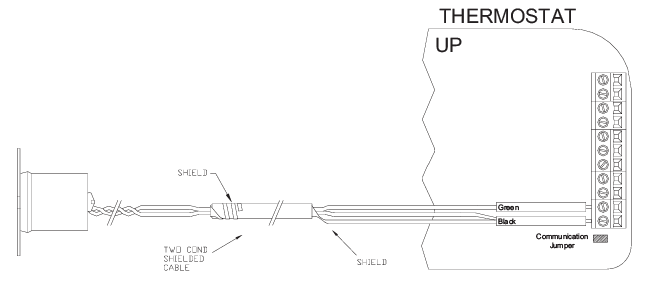
Notes:
- When connecting a remote temperature sensor, the shield and one of the wires from the remote temperature sensor are tied together and get connected to the Black terminal – See Figure 14.
- At the location of the temperature sensor, wrap the shield around the jacket of the cable and tape.
- Configure the temperature sensor according to the application – See “Temperature Sensors” under Installation Settings.
Anticipator Control
The Anticipator Control settings are used to “anticipate” the need to turn the system on or off before the temperature is actually at the setting. As humans, we perceive temperature as a combination of heat in the air and heat radiated from the walls and surroundings. The thermostat also measures a combination of air and wall temperature. When heating, the air temperature rises faster than the wall temperature. The thermostat will turn the heat off briefly to prevent overheating the air while the wall temperature catches up. When cooling, the thermostat will periodically run the cooling system to circulate the air and remove humidity when the temperature is close to, but not above the desired cool setting. Because of the PID algorithm and auto balance routine which monitors the performance of the HVAC system, the anticipator settings are automatic by default. However, the anticipator settings may be adjusted if desired.
Heat Anticipator: This adjusts the tendency of the thermostat to turn the heating unit off before the desired heat setting is reached. This is done to avoid overheating the air while the walls and furniture catch up. A setting of 0-4 is intended for fast-reacting heating systems, such as forced air. A setting of 6-10 is intended for slow-reacting heating systems, such as radiant heat. A setting of 5 is used for automatic anticipation. A lower setting will decrease the tendency to turn off the heating system before the desired heat setting is reached. If the heating system response time is slower, as are most radiant heating systems, a higher number will help maintain an even space temperature.
Cool Anticipator: This adjusts the tendency of the HVAC to run the cooling system to refresh and dehumidify the air before the temperature rises to the desired cool settings. A setting of 0-4 is intended for more humid climates and will increase the tendency for the cooling system to turn on to refresh and dehumidify the air. A setting of 6-10 is intended for dry climates and will decrease the tendency to run the cooling system below the cooling setting. A setting of 5 is used for automatic anticipation.
2nd/3rd Stage Extended On: When enabled and if any 2nd or 3rd stage turns on, it will remain on until the heat/cool is satisfied, regardless of the settings for any stage differentials. The default setting is off.
| Cool Anticipator | *5 |
| Heat Anticipator | *5 |
| 2nd/3rd Stage Extended On | *Off |
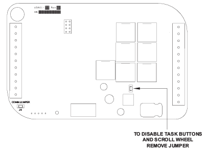
DISABLE LOCAL CONTROL
The Task Buttons and Scroll Wheel on the thermostat can be disabled to prevent anyone from controlling the thermostat locally. To disable the Task Buttons and Scroll
Wheel
- Remove the thermostat face from the thermostat base.
- Remove the local control jumper
- Align the tabs of the thermostat face with the slots of the thermostat base.
- Gently push the thermostat face into the thermostat base locking it into place
SETUP AND CONFIGURATION
Note: For proper operation of the features of this thermostat, the Time and Date must be set. Even when connected to an HAI controller which sets the time and day, the Date must be manually set in the thermostat under the “Settings” menu.
INSTALLATION SETTINGS
This section describes the items that the installer must setup as part of the thermostat installation. The Installation Settings menu is used to configure the operating parameters of the thermostat.
To access the Installation Settings mode:
- From the Home Page, press the Scroll Wheel.
- Turn the Scroll Wheel until “Setup” is highlighted.
- Press the Scroll Wheel or [Select] to select “Setup”.
- Turn the Scroll Wheel until “Installation Settings” is highlighted.
- Press the Scroll Wheel or [Select] to select “Installation Settings”.
- Read the warning and then press [Continue] to proceed.
- To exit Setup mode, press [Back] several times until the Home Page is displayed.
Temperature Sensors
The Temperature Sensor settings are used to configure the internal temperature sensor and optional remote temperature sensors that are connected to the thermostat. Any temperature sensors that are set as the same type (i.e. indoor or outdoor) will display the average temperature reading among the sensors.
- Internal Sensor: This will enable or disable the onboard temperature sensor for indoor use only. *Enabled
- External Sensor 1: This will enable the external temperature sensor for indoor or outdoor use. All indoor and outdoor temperatures are averaged between all sensors of the same type. *Disabled
- External Sensor 2: This will enable the expansion module temperature sensor for indoor or outdoor use. All indoor and outdoor temperatures are averaged between all sensors of the same type. *Disabled
- External Sensor 3: This will enable the expansion module temperature sensor for indoor or outdoor use. All indoor and outdoor temperatures are averaged between all sensors of the same type. *Disabled
Humidity Options
The Humidity Options are used to configure the dehumidifier and/or humidifier output on the thermostat.
- Not Used: Dehumidifier/Humidifier output is disabled.
- Fan Speed Control: This option uses the dehumidifier output to control the fan speed on an HVAC system with a variable-speed fan. When energized, the fan speed is reduced to augment the dehumidification process.
- Dehumidifier: This option uses the dehumidifier output to control a stand alone dehumidifier.
- Humidifier: This option uses the humidifier output to control a standalone humidifier.
- EM Heat: EM Heat is displayed if the respective output is configured as an Emergency Heat Output as described under Emergency Heat Options. If configured as an Emergency Heat Output, the output cannot be modified under Humidity Options; it must first be reconfigured under Emergency Heat Options.
| Dehumidifier Output | Humidifier Output |
| *Not Used | *Not Used |
| Dehumidifier | Humidifier |
| Fan Speed Control |
EM Heat |
| EM Heat |
Notes:
- The thermostat will automatically default to the Home Page after 3 minutes of no key activity.
- The word “default” indicates the initial setting when the thermostat is delivered from the factory.
- Unless otherwise noted, an asterisk (*) next to a setup item indicates the default setting.
Thermostat Address
If you are using remote communications and you are installing more than one thermostat, each must be set to a unique address. The default address setting is 1. An address from 1- 127 may be selected.
Communications Mode
The thermostat can communicate with remote systems in different modes.
|
Communications |
*Serial: RS-232 mode for use with personal computers and automation systems. | ||||
| Day/Night: The thermostat remotely communicates with a remote setback
switch. |
|||||
| System Baud | *100 | 300 | 1200 | 2400 | 9600 |
| Expansion Baud | 100 | 300 | *1200 | 2400 | 9600 |
The following modes are available:
|
System Type |
*Conventional ———————————-
Zone Control |
Dual Fuel Heat Pump1 ————————— Geothermal Dual Fuel Heat Pump1 |
Heat Pump ———————– Geothermal Heat Pump |
|||||||||
|
System Mode |
*Auto Changeover | Auto Changeover | Auto Changeover | |||||||||
| Manual Changeover | Manual Changeover | Manual Changeover | ||||||||||
| Heat Only | ||||||||||||
| Cool Only | ||||||||||||
|
Fan On with Heat Stage |
*None | 1 | 2 | 3 | *1, 2,
and 3 |
1 | 2 | 3 | *1, 2,
and 3 |
1 | 2 | 3 |
| 1
and 2 |
1
and 3 |
2
and 3 |
1, 2,
and 3 |
1
and 2 |
1
and 3 |
2
and 3 |
1
and 2 |
1
and 3 |
2
and 3 |
|||
System Options
Note: Before operating the thermostat, the “System Type” and “System Mode” must be configured. The thermostat can be configured with the following system options
Emergency Heat Options
The Emergency Heat Options are used to reconfigure the H (Humidifier) or D (Dehumidifier) outputs on the RC-2000 to activate when the thermostat is in Emergency Heat mode. The default address setting is “None”.
Note: The H (Humidifier) and D (Dehumidifier) output will operate as described under Humidity Options.
- D Terminal: This option configures D (Dehumidifier) output on the RC-2000 to activate when the thermostat is in Emergency Heat mode.
- H Terminal: This option configures H (Humidifier) output on the RC-2000 to activate when the thermostat is in Emergency Heat mode.
Balance Setpoints (Dual Fuel Heat Pump)
The Balance Setpoints are used to determine when the auxiliary heat is used in a dual fuel heat pump system
- If the outdoor temperature is above the “Upper Balance Setpoint” (45°F by default), the heat pump is used exclusively.
- If the outdoor temperature falls below the “Upper Balance Setpoint” but is above the “Lower Balance Setpoint” (35°F by default) and if the heat pump is unable to heat at a rate of 5 degrees per hour or better, the heat pump will turn off and the auxiliary heat will be used until the temperature rises above the “Upper Balance Setpoint” or the call for heat has been satisfied.
- If the outdoor temperature falls below the “Lower Balance Setpoint”, the heat pump will turn off and the auxiliary heat will be used until the call for heat has been satisfied.
Installer Lockout
When this option is set to [Yes], the “Installation Settings” menu option is removed from the “Setup” menu to prevent access to these settings. To access the “Installation Settings” menu, from “Setup” menu, simultaneously press Task Buttons 1 (left), 2 (center), and the Scroll Wheel; “Installation Settings” will appear.
Factory Default
This option will restore all system settings and programming to factory fresh configuration. Read the warning and then press [Yes] to proceed or [Cancel] to return to Installation Settings.
Program Options
This thermostat has been preprogrammed with energy saving program schedules. When used with a remote system, it is recommended that the Program Mode be configured as “None” or “Occupancy”. This will disable the internal program schedules. The program options setting sets the method for scheduling temperature change commands.
|
Program Mode |
*Schedule: Program setpoints are based on time of day and day of week. |
| None: The internal program schedule is disabled Us.e this when connected to a remote system for temperature change commands. | |
| Occupancy: Program setpoints are based on the occupancy status
of a remote system. Status options are Day, Night, Away, and Vacation. This mode is also used with a remote setback switch. Note: A remote system or switch is required. |
Calibration Offset
This item is used to raise or lower the current temperature reading from the onboard temperature sensor by .5 degree Fahrenheit or .25 degree Celsius. The default setting is 0.00.
Cool/Heat Limit
These items are used to limit the desired temperature settings in cool and heat mode. The desired cool setting can never be set below the “Cool Setpoint Min” setting and the desired heat setting can never be set above the “Heat Setpoint Max” setting. The default setting for cool is 51°F. The default setting for heat is 91°F.
Cool/Heat Min On/Off
These items are used to limit the on and off times of the cooling and heating system (in minutes).
|
Cool Minimum On |
The number of minutes the thermostat forces the cooling system to
remain on before turning off. Raising this number will increase the total time the cooling system is on (saving energy), but may allow the temperature to drift farther from setpoint (decreasing comfort). When combined with Cool Minimum Off, cycles per hours can be obtained by using the following calculation: 60 / (Cool Minimum On + Cool Minimum Off). The default time is 6 minutes. |
|
Cool Minimum Off |
The number of minutes the thermostat forces the cooling system to remain off before starting again. Raising this number will increase the
total time that the cooling system is off (saving energy), but may allow the temperature to drift farther from the setpoint (decreasing comfort). When combined with Cool Minimum On, cycles per hours can be obtained by using the following calculation: 60 / (Cool Minimum On + Cool Minimum Off). The default time is 6 minutes. |
WARRANTY
LEVITON LIMITED WARRANTY
Leviton warrants to the original consumer purchaser and not for the benefit of anyone else that products manufactured by Leviton under the Leviton brand name (“Product”) will be free from defects in material and workmanship for the time periods indicated below, whichever is shorter:
- OmniPro II and Lumina Pro: three (3) years from installation or 42 months from manufacture date.
- OmniLT, Omni IIe, and Lumina: two (2) years from installation or 30 months from manufacture date.
- Thermostats, Accessories: two (2) years from installation or 30 months from manufacture date.
- Batteries: Rechargeable batteries in products are warranted for ninety (90) days from date of purchase.
Note: Primary (non-rechargeable) batteries shipped in products are not warranted. Products with Windows® Operating Systems: During the warranty period, Leviton will restore corrupted operating systems to factory default at no charge, provided that the product has been used as originally intended. Installation of non-Leviton software or modification of the operating system voids this warranty. Leviton’s obligation under this Limited Warranty is limited to the repair or replacement, at Leviton’s option, of Product that fails due to defect in material or workmanship. Leviton reserves the right to replace product under this Limited Warranty with new or remanufactured product. Leviton will not be responsible for labor costs of removal or reinstallation of Product. The repaired or replaced product is then warranted under the terms of this Limited Warranty for the remainder of the Limited Warranty time period or ninety (90) days, whichever is longer. This Limited Warranty does not cover PC-based software products. Leviton is not responsible for conditions or applications beyond Leviton’s control. Leviton is not responsible for issues related to improper installation, including failure to follow written Installation and operation instructions, normal wear and tear, catastrophe, fault or negligence of the user or other problems external to the Product. To view complete warranty and instructions for returning product, please visit us at www.leviton.com
COPYRIGHT AND TRADEMARK INFORMATION
This document and all its contents herein are subject to and protected by international copyright and other intellectual property rights and are the property of Leviton Manufacturing Co., Inc, its subsidiaries, affiliates and/or licensors. © 2013 Leviton Manufacturing Co., Inc. All rights reserved. Use herein of third party trademarks, service marks, trade names, brand names and/or product names are for informational purposes only, are/may be the trademarks of their respective owners; such use is not meant to imply affiliation, sponsorship, or endorsement. No part of this document may be reproduced, transmitted or transcribed without the express written permission of Leviton Manufacturing Co., Inc.
FCC
This equipment has been tested and found to comply with the limits for a Class B digital device, pursuant to part 15 of the FCC Rules. These limits are designed to provide reasonable protection against harmful interference in a residential installation. This equipment generates, uses and can radiate radio frequency energy and, if not installed and used in accordance with the instructions, may cause harmful interference to radio communications. However, there is no guarantee that interference will not occur in a particular installation. If this equipment does cause harmful interference to radio or television reception, which can be determined by turning the equipment off and on, the user is encouraged to try to correct the interference by one or more of the following measures:
- Reorient or relocate the receiving antenna.
- Increase the separation between the equipment and the receiver.
- Connect the equipment into an outlet on a circuit different from that to which the receiver is connected.
- Consult the dealer or an experienced radio/TV technician for help.
FOR CANADA ONLY
For warranty information and/or product returns, residents of Canada should contact Leviton in writing at Leviton Manufacturing of Canada Ltd to the attention of the Quality Assurance Department, 165 Hymus Blvd, Pointe-Claire (Quebec), Canada H9R 1E9 or by telephone at 1 800 405-5320.
REFERENCE
DOWNLOAD MANUALS:
Leviton RC-2000 Digital Wireless Thermostat User Guide
OTHER MANUALS:
Leviton RC-2000 Digital Wireless Thermostat Product Data Sheet
![]()
Leave a Reply