
Lennox CS8500 Commercial Programmable Thermostat
Shipping and Packing List
Verify the following items have been included in the packing:
Table 1. Packing List
| Quantity | Item |
| 1 | CS8500 (non-zoning) with back plate |
| 1 | Wall plate |
| 2 | Wall anchors |
| 2 | Screws (M3.5x24mm self-tapping) |
| 1 | Warranty |
| 1 | User guide |
| 1 | Setup and installation guide |
WARNING
Improper installation, adjustment, alteration, service or maintenance can cause property damage, personal injury or loss of life.
Installation and service must be performed by a licensed professional HVAC installer (or equivalent) or service agency.
CS8500 Features
The ComfortSense® 8500 (CS8500) is a commercial, electronic, 7-day, multi-stage, programmable, touchscreen thermostat. This CS8500 provides temperature control for packaged gas/electric and electric/electric for up to 4-heat / 4-cool multi-stage rooftop unit systems (not for heat pump systems).
- Models are available with or without CO2 sensing capabilities.
- For use with Energence® commercial rooftop units equipped with Prodigy®.•For use with iCON Intelligence Connected™ by Lennox® building-automation solution.
- CO2 models can be used to control Lennox’s premium rooftop unit Demand Control Ventilation features based on CO2 set points and conditions stored In the unit controller.
- The CS8500 also features enhanced capabilities including remote temperature sensing, dehumidification and control, economizer control, and custom reminders.
Built-in humidification monitoring – range 5% to 95% with accuracy at + 5%. - Built-in carbon dioxide monitoring version only – range 400-2000 ppm, range 5% to 95%, and with accuracy at + 40 ppm + 3% or reading @ 77°F (25°C).
- The sensor has a built-in self-calibration algorithm.
- Temperature monitoring – two internal thermistors, range 32°F (0°C) to 99°F (37°C). Measurement accuracy + 0.5°F (-17.5°C).
- External indoor temperature sensor connections 10kΏ (47W37) or 11kΏ (94L61) — up to nine (9) sensors in parallel may be used.
- External occupancy sensor connection (24VAC).
- Supports 50 and 60Hz operations.
- Maximum load per terminal – 1 amp
- Power supply range 18 to 30 VAC
- Temperature control is (+/- 1⁰F) of set point
Product Dimensions
- Unit Dimensions (H x W x
- Case dimensions: 3-5/16 x 4-5/16 x 7/8 in. (84 x 110 x 22mm)
- Wall Plate Dimensions (H x W)
- Plate dimensions: 4-1/2” x 5-3/4” (114 x 146mm)
Wiring Specifications
Communication Wire
Use one of the following Lennox communication cables (twisted pair with shield plenum):
Table 2. Twisted Pair Communication Wiring (S-Bus – Yellow)
| Catalog Numbers | Item |
| 27M19 | 500-foot roll |
| 94L63 | 1000 foot roll |
| 68M25 | 2500 foot roll |
CAUTION
This is a 24VAC low-voltage sensor. Do not install on voltages higher than 30VAC.
Do not short (jumper) across terminals to test installation. This will damage the sensor and void the warranty.
Remote Sensor Wire
All remote sensors use standard non-shielded thermostat wiring; sensors may be wired using two wires of a multiple-wire cable.
NOTE:
Outdoor and indoor sensor wire runs should not exceed 300 feet (100m).
Transformer Wire
Standard thermostat wire (one pair 20 AWG minimum) may be used to wire the CS8500 to the optional wall plug 24VAC transformer (18M13) or other field-provided 2VA minimum, 24VAC output transformer.
Installation
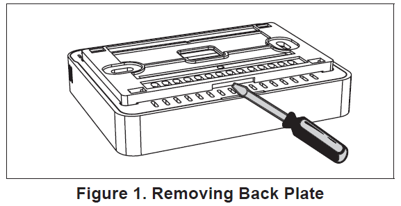
- Unpacked the CS8500 and open the case with a thin-blade screwdriver (see “Figure 1. Removing Back Plate” on page 5).
- Place between wall base and unit and twist to separate unit from base.
- Select a location for the sensor about five (5) feet (1.5 meters) above the floor in an area with good air circulation at an average temperature.
- Do not install the CS8500 where it can be affected by:
- Drafts or dead spots behind doors and in corners.
- Entrance or automatic doors.
- Heat-generating equipment such as kitchen equipment.
- Enclose the environment unless a remote indoor sensor is used.
- Hot or cold air from ducts.
- Radiant heat from sun or appliances.
- Concealed pipes and chimneys.
- Non-heated or non-cooled areas such as an outside wall behind the sensor.
- Use the following steps:
- Determine location using best practices.
- Use the provided wall plate as a template to determine the location cutout for wiring and the location for wall anchors.
NOTE:
The use of the provided wall plate is optional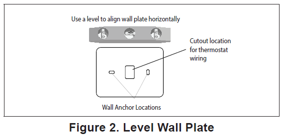
- Cut or drill a small hole approximately 3/4” x 3/4” for wiring.
- Pull about three inches of all wiring through the opening and remove the outer communication wire jacket.
- Trim 1/4” insulation from the end of each wire.
- Drill 3/16” holes at marked locations on the wall for wall anchors.
- Route the CS8500 and outdoor temperature sensor (optional) wiring from the wall through center openings on the wall plate (use is optional) and back plate (see “Figure 3. Route Wiring” on page 6).
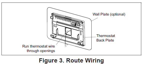
- Secure the back plate and wall plate (optional) to the wall with the two provided mounting screws
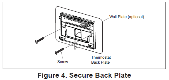
- Remember to seal the hole in the wall with a suitable material to prevent drafts from entering the zone sensor case. Not doing so could affect the internal temperature and humidity sensors.
Terminal Connections
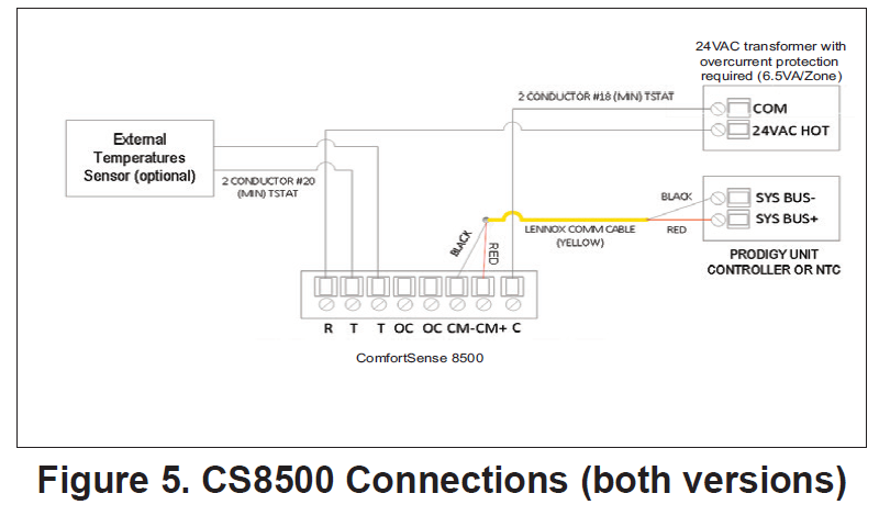
External sensors use standard thermostat wiring; and may be wired using two wires of a multiple-wire cable. Wire run should not exceed 300 feet (100m).
Terminals CM- and CM+ will use wiring as referenced in “Table 2. Twisted Pair Communication Wiring (S-Bus – Yellow)” on page 4.
Table 3. Twisted Pair Communication Wiring (S-Bus – Yellow)
| Terminals | Purpose |
| R | 24VAC |
| T T | External indoor temperature sensor
(10KΏ or 11KΏ ) |
| OC OC | Occupancy sensor |
| CM- CM+ | S-Bus communication |
| C | 24VAC common |
IMPORTANT!
Damage to the ComfortSense 8500 may occur if 24VAC polarity is not maintained.
Wiring CS8500 (with or without CO2 Sensor)
Below are the terminal designations and a general description of their purpose.
- Connect wiring between CS8500 and the applicable controller.
- Connect external sensors if applicable.
- Seal the hole in the wall with a suitable material to prevent drafts from entering the CS8500 case.
- Configure CS8500 and equipment for the system type and test system.
Installing Indoor Temperature Sensors
Wire external sensors as illustrated below. Up to nine sensors may be used in averaging sensor applications. Use Lennox catalog numbers 10kΏ (47W37) or 11kΏ (94L61). Sensors are not polarity sensitive.
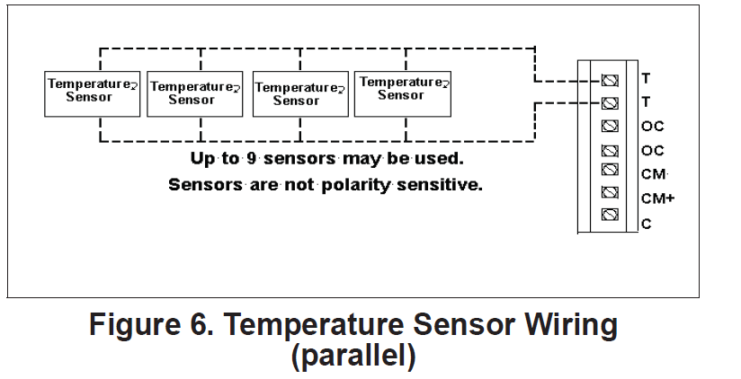
The CS8500 will calculate the average temperature readings from all connected external temperature sensors. If any of the sensors malfunction, they may still report a temperature value. Only when the average value of the connected temperature sensors including any malfunction sensor(s) is lower than -40°F, or higher than 158°F, will the CS8500 determine that an external temperature sensor(s) has failed and switched automatically to the CS8500’s internal temperature sensor. An error message will be displayed on the home screen and under the notification screen indicating an “external temperature sensor” error.
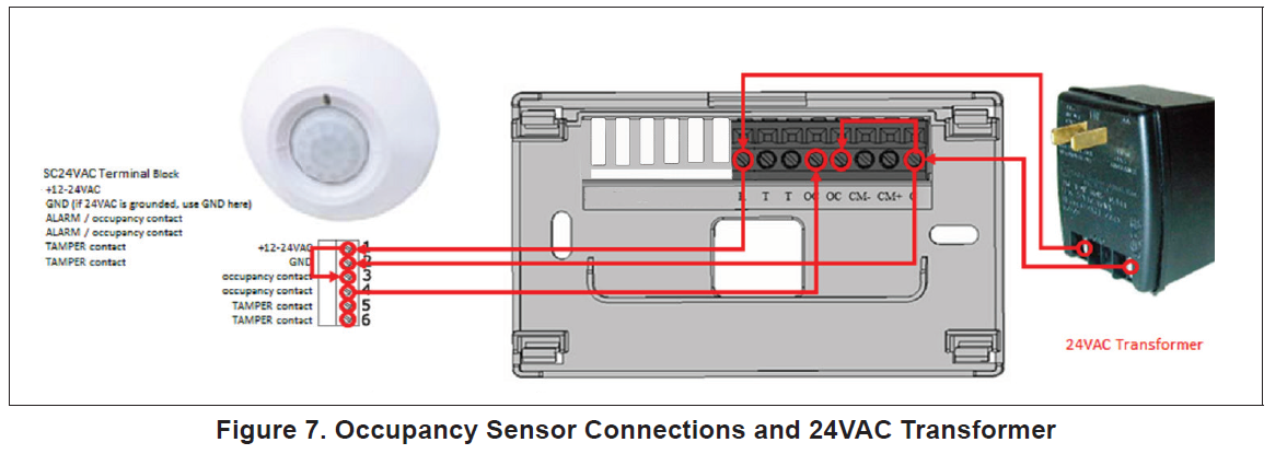
Installing Occupancy Sensor
The occupancy sensor will output:
- 4VAC in occupied mode.
- VAC is in unoccupied mode.
The following is an example on how to make connections for an occupancy sensor.
iCON / L Connection Equipment
A single CS8500 can be connected directly to the S-Bus connection on the Prodigy Unit Controller. The optional settings (M2 ECTOs or M3 Parameters) can be adjusted using Unit Controller software, a PC with UC software, and L Connection PC converter. All parameters can also be set directly at the Unit Controller. Refer to the applicable unit controller application guide to edit the required ECTOs or parameters.
Network Thermostat Control (NTC) Setup
- TC ECTO A4.07 is factory set to option 0 (local). In this system mode, the NTC will operate the unit based on input from a local sensor.
- TC ECTO A4.07 must be set to option 1 (remote) if an L Connection communication compatible ComfortSense 8500 is used. In this system mode, the
- NTC will operate the unit based on input from the ComfortSense 8500
M1 / M2 Unit Controller Setup
From the main menu, perform the following navigation through the menus to set the S-Bus address for L Connection Go to:
- Settings > Control > Guided Setup > Enter Advanced Guide Setup > Set Control > LCONN > ADDR
- Enter the S-Bus address for L Connection. Once done select the Set option to save the settings.
- M1 / M2 Unit Controller – Control Mode and Backup Set Points Setup
- The following unit controller ECTOs must be set when using the CS8500.
- ECTO 5.27 – This is used and depends on the available sensors on the CS8500. The room temperature reading is standard on all models. The following setting instructs the M1/M2 unit controller what source to get zone temperature, CO2, and indoor RH input.
- 2 = Room temperature (A2)
- 3 = Room temperature and IAQ (A63)
- 10 = Room temperature and indoor RH (A91)
- 11 = Room temperature, IAQ, and indoor RH
- ECTO 6.01 – Is used to configure the M1/M2 unit controller control mode and backup set points to use. Options are:
- 1 = Zone sensor mode with no backup.
- 2 = Zone sensor mode with local sensor backup
- 3 = Zone sensor mode with return air sensor backup.
M3 Unit Controller Setup
From the main menu, perform the following navigation through the menus to set the S-Bus address for L Connection.
- Go to SETUP > NETWORK INTEGRATION > L-CONNECTION > LCONN ADDRESS.
- Enter the desired LCONN ADDRESS (S-Bus) and select SAVE to continue.
- Set CONTROL MODE = ROOM SENSOR and select SAVE to continue.
- NETWORK SENSOR CO2 (if equipped) needs to be set to YES (if choosing CO2 from CS8500). Select SAVE to continue.
- RELATIVE HUMIDITY needs to be set to YES (if choosing RH from CS8500). Select SAVE to continue.
- TEMPERATURE will need to be set to YES (if choosing temperature from CS8500).
- Continue to answer the various configuration questions until it returns you to the NETWORK INTEGRATION menu option.
NOTE:
Once the configuration is saved, then S-Bus communication will be lost and alarm 110 (low priority) will be raised. This will be cleared automatically when any demand goes to M2/M3.
CS8500 Setup
- From the CS8500’s home screen, go to MENU > TECHNICIAN SETTINGS and enter 864, and press OK to proceed.
- Both the RTU and the CS8500 must be set to the same S-Bus address. The rooftop unit’s default address is 2 unless it has been changed. Set the CS8500 S-Bus address to match the rooftop unit’s S-Bus address.
- Set operation with Smart Hub (central hub or NCP) to ON/OFF.
- If the CS8500 is set up with the rooftop units with an NCP set this to ON.
- If the CS8500 is set up with the rooftop units and no NCP set this to OFF.
- If the CS8500 is being used in an iCON by Lennox automation system with a Central Hub, set this to ON.
NOTE
It may take 30 seconds up to two minutes for the CS8500 to connect.
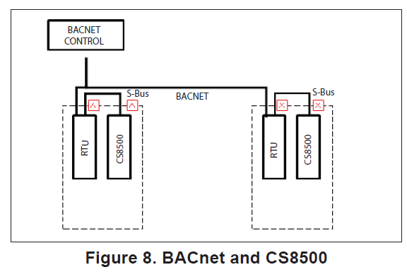
BACnet with M3 Unit Controller
This section describes how a CS8500 operates in a BACnet environment with an M3 unit controller.
Network Topology
- All rooftop units are connected to the BACnet front end.
- Each rooftop unit is connected to one CS8500.
- The CS8500 communicates with the rooftop units using the Lennox proprietary S-Bus protocol.
CS8500 Set Point Change
The BACnet front-end provides the occupied and unoccupied set points to the rooftop unit. The rooftop unit (RTU) sends the same set points to CS8500. The rooftop units uses these set points until the CS8500 provides a new set point. When the user changes the set point at the CS8500, it communicates the same to M3 unit controller. Upon receiving this information, the M3 unit controller starts an override timer and uses the new set points until the timer expires.While the timer is active, if BACnet queries the M3 unit controller, it will be informed that the rooftop units is using the override set points. When the timer expires, both the M3 unit controller and CS8500 revert to the set points provided by BACnet.
CS8500 Occupancy Override
- Rooftop units use occupied or unoccupied set points based on the occupancy status supplied by the BACnet front-end.
- The user has the option to force the system into occupied status using the CS8500.
- When the user overrides occupancy at the CS8500, it communicates the same to M3 unit controller.
- Upon receiving this information, the M3 unit controller starts an override timer and uses the occupied set points until the timer expires.
- The CS8500 also remains in occupied mode as long as the override timer is active.
- While the timer is active, if BACnet queries the M3 unit controller, it will be informed that the rooftop unit is using the occupied set points.
- When the timer expires, both the M3 unit controller and CS8500 revert to the occupancy status provided by BACnet.
BACnet Canceling Override
When the user changes the set point or occupancy mode at the CS8500, it puts the M3 unit controller into override mode. The BACnet front-end has the option to cancel the override timer at any time by sending a value of 3 to BACnet Analog Object 103. When the timer is canceled, the rooftop units and CS8500 returns to using the occupancy status or set points provided by the BACnet front-end.
Sensor Inputs
The M3 unit controller can be configured to use tem-perature, relative humidity and/or CO2 provided by the CS8500.
NOTE: Occupancy sensor input from the CS850 cannot be utilized in this mode.
M3 Unit Controller Setup
BACnet compatibility with the M3 unit controller requires firmware version 08.03.0120 or higher. To configure the M3 unit controller to work with the CS8500 use the following procedure:
- Go to MAIN MENU > SETTINGS > RTU OPTIONS > EDIT PARAMETERS. Edit parameter 385 and set to 1.
NOTE: Modifying 385 to 1 allows both the CS8500 and M3 unit controller to co-exist.) - Go to Prodigy MAIN MENU > SETTINGS > GENERAL and set CONFIGURATION ID1, position 5 to B.
- Go to SETUP and select NETWORK INTEGRATION.
- Use the adjust and set values arrows to display L- CONNECTION and press the SAVE button to continue.
- djust the L-CONNECTION ADDRESS if required and press SAVE button to continue.
- CONTROL MODE will need to be set to ROOM SENSOR. Press the SAVE button to continue.
- NETWORK SENSOR > CO2 needs to be set to YES (optional). Press the SAVE button to continue.
- NETWORK SENSOR > RELATIVE HUMIDITY needs be set to YES (optional). Press the SAVE button to continue.
- NETWORK SENSOR > TEMPERATURE will need to be set to YES (optional).
- Continue to answer the various configuration questions until it returns you to the NETWORK INTEGRATION menu option.
- Go to SETUP and select NETWORK INTEGRATION.
- Use the adjust and set values arrows to display BACNET and press the SAVE button to continue.
- Adjust the BACNET ADDRESS if required and press SAVE button to continue.
- Adjust the BACNET BAUD RATE and press SAVE button to continue.
- CONTROL MODE will need to be set to ROOM SENSOR. Press the SAVE button to continue.
- NETWORK SENSOR > CO2 (if equipped) needs to be set to NO (if choosing CO2 from CS8500). Press the SAVE button to continue.
- NETWORK SENSOR > RELATIVE HUMIDITY needs be set to NO (if choosing RH from CS8500).
- NETWORK SENSOR > TEMPERATURE will need to be set to NO (if choosing temperature from CS8500).
- Continue to answer the various configuration questions until it returns you to the NETWORK INTEGRATION menu option.
CS8500 Setup
- From the CS8500’s home screen, go to MENU> TECHNICIAN SETTINGS settings and enter 864 and press OK to proceed.
- Both the RTU and the CS8500 must be set to the same S-Bus address. The RTU default address is 2 unless it has been changed. If it has not change then set the CS8500 S-Bus address to 2.
- Set operation with Smart Hub (Central Hub) to ON.
CS8500 Sensor Failure
If the CS8500 sensor fails, the RTU will revert to its return air temperature for space temperature and set points from BACnet.
Functions Not Supported
- Zoning
- Occupancy sensor input from the CS8500.
- BACnet in monitor mode.
- BACnet cannot refresh/reload the set point override timer.
CS8500 Troubleshooting
- Make sure 24VAC is supplied to the CS8500.
- Make sure the CS8500 S-Bus address setting matches the M2/M3 unit controller address.
NOTE: NCP is required when using an NTC. - Check communication cable wiring.
- Verify that the sensor data from the CS8500 display matches the Prodigy Unit Controller display.
- For the M1 unit controller (IMC), use the IMC MODE TEMP switch to display the data.
- For the M2 unit controller:
Go to: DATA > SENSORS menu to display the data. - For the M3 unit controller:
Go to: DATA > IN/OUTPUT > SENSORS >
M3 Unit Controller – Setting Return Air Temperature Limits
The M3 unit controller may be set up to monitor return air temperature and interrupt the demand if return temperature is above the heating adjustable limits. To enable this feature set parameters 113 and 115 locally at the M3 unit controller which is located inside the Lennox rooftop unit.
- Adjusting parameter 113 enables return room temperature limits. Default is 0 (OFF). To enable set to 1 (ON).
- Go to: SETTINGS > RTU OPTION > EDIT PARAMETER = 113 (EN RET AIR TMP LMT).
- Adjusting parameter 115 is used to interrupt a heating demand. Default is 85.0°F. The adjustable range is 60.0°F to 100.0°F.
- Go to: SETTINGS > RTU OPTION > EDIT PARAMETER = 115 (HEAT RET AIR LIMIT)
- If return air temperature is above the adjustable limits, alarm code 40 will be displayed but not stored in memory for recall.
Select the three lines in the upper right-hand corner of the home screen to access the menu. Selectable options under menu are notifications and settings.
NOTE
- Refer to the included user guide for more details on the following menu selections.
- notifications – When a system error or reminder occurs, a pop-up screen will appear indicating the condition. (See user guide for details.)
- Performance Reports (only available when“Operation with Smart Hub” is set to OFF.) (See user guide for details.)
NOTE: - Smart Hub reference is concerning Central Hub
- Edit Schedule (only available when “LocalScheduling Function” is set to ON.) (See user guide for details.)
- Owner Settings (See user guide for details.)
- Technician Settings (See the following sectionfor details).
Technician Settings
During initial power-up of the CS8500, the technician settings menu will appear first. The S-Bus address option must be selected and an address set before you can proceed. Use either the minus/plus buttons or numeric keypad to enter the address. After the S-Bus address is set, press the back button to return to the technician settings menu.
NOTE:
If you need to access the technician settings option in the future, go to the home page, press menu > technical settings and enter technician PIN code 864. This code cannot be changed.
Parameter Settings Based on System Configuration
The first parameters (S-Bus Address) will always need to be set. Available bus addresses are 1 through 31. Other settings are available based on whether operations with smart hub and local scheduling functions is set to ON or OFF. Parameter Settings Based on System Configuration The first parameter (S-Bus Address) will always need to be set. Available bus addresses are 1 through 31 Other settings are available based on whether operations with smart hub and local scheduling functions is set to ON or OFF.
Table 4. Parameter Settings based on System Configuration
|
Parameters |
Setting Available when Operation with Smart Hub is ON or OFF | Setting Available when Local Scheduling is set to ON or OFF |
| Display on home screen | ON or OFF | ON or OFF |
| Contractor info | ON or OFF | ON or OFF |
| Temperature sensor config. | ON or OFF | ON or OFF |
| Smooth setback recovery (SSR) | OFF | ON |
| Offsets | ON or OFF | ON or OFF |
| Temperature adjustment range | ON or OFF | ON or OFF |
| Remember override set point | OFF | ON |
| Schedule hold setting | OFF | ON |
| Reminders | OFF | ON or OFF |
| Reset to factory defaults | ON or OFF | ON or OFF |
| Change owner pin | ON or OFF | ON or OFF |
| RTU fan on/auto user control | ON or OFF | ON or OFF |
Parameter Descriptions
S-Bus Address
Options are 1 through 3
- Select an address and press the set button to save the setting and return to the technician setting screen.
NOTE: The s-Bus address should be the same as the address being used by either the NTC or unit controller which you wish to control with the CS8500. - Operation with Smart Hub When set to off the CS8500 can communicate directly with a Prodigy Unit Controller via the S-Bus. Default is off. In addition, when set to ON, this function will allow the CS8500 to operate in a BACnet network with an M3 Unit Controller or operate with an iCON Hub / NTC.
- Local Scheduling FunctionThis feature provides the ability to setup a local schedule. When set to ON, several options are available. Once schedules have been defined, the scheduling function can be turned on from the home screen by selecting heat/cool on the home screen and select mode schedule.
If the ComfortSense 8500 is in stand-alone mode, local scheduling can be used. Adjusting the temperature set points on the CS8500 will put the unit in an override period. - Display on the Home Screen
- Turn ON or OFF for the following options. The factory default is set to OFF.
- RTU Fan
- CO2 value (only on models with CO2 sensor)
- RTU function state
- Service required alert
- Factory default is OFF for all of the above options. Press < in the upper left-hand corner of the screen to return to the technician settings menu
- Contractor InfoInformation to be completed for this option is name, address, phone, email, and website. Press < in the upper left-hand corner of the screen to return to the technician settings menu.
- Temperature Sensor Config
- Temp. Sensor source by default is set to internal temp. sensor. The other option is external temp. sensor(s). When external temp. sensor(s) is selected, the following settings need to be configured;
- Number of external temp. sensor. Default is 1 and up to 9 can be selected.
- Type of external sensor. Options are 10k sensor type 2 (47W37) or 11k sensor type 2 (94L61). Default sensor type is 10k sensor type 2.
- Press < in the upper left-hand corner of the screen to return to the technician settings menu
- Smooth Setback Recovery (SSR)Options are enable or disable. Default is Enabled. When enabled, smooth set recovery begins recovery up to two hours before the programmed time so that the programmed temperature is reached 6°F per hour at the corresponding programmed event time and is applicable for all equipment settings. With smooth set recovery disabled, the control will start a recovery at the programmed time.
- Offsets
- internal temp. Sensor offset: Offset for the built-in temperature sensor (internal) is -5°F to +5°F. Default is 0°F.
- external temp. sensor offset (only selectable when external temp. sensor is selected under temperature sensor config.): Offset for the external temp, the sensor is -5°F to +5°F. Default is 0°F.
- Humidify offset: The setting option for this is -10% to +10%. Default is 0%.
- CO2 sensor offset: Offset for the CO2 sensor is -200ppm to + 200 ppm. Default is 0 ppm. (Only on models with internal CO2 sensor.)
- Temperature Adjustment Range The adjustment range for screen unlock is 0 to 10 degrees in increments of one degree. The default setting is 2. There is a ON / OFF adjustment for screen lock as well.When the Local Scheduling function is set to OFF and operations with the Smart Hub is set to OFF, the CS8500 will use the heating and cooling, unoccupied and occupied set points from the Prodigy controller. These can only be adjusted at the rooftop unit.
- Remember Override Set PointThis setting is only available when local scheduling is set to ON. When an override is set the status text will display “Period of Time” instead of “Schedule Hold”When an override is set the unit will remember this override setting for the current occupied period and re-apply it at the same occupied period, every time it occurs.This setting will be able to be enabled or disabled.
- Schedule Hold SettingsThis is a setting for hold until next scheduled period option. Options are enable or disable. Default is enabled.
When a user sets an override the unit will allow the user to set the duration of the override to “1 hour, 2 hours, or Until the Next Scheduled Period.The Technician Settings can allow a user to disable the “Until Next Scheduled Period” option when unoccupied. This option applies to stand-alone mode.
12.RemindersTwo customer reminders can be set and a routine system check up.- or both reminders, the name change be customized and date and time set.
- For routine system check up the date and time can be set. 13.Reset to Factory Defaults
- There are five options under this setting, partial reset and all reset.
- Reset reminders.
- Reset schedule.
- reset all settings – Resets everything to default.
- Reset all owner settings – Resets all owners settings listed under general display menus.
- Reset technician settings: Resets all technician settings listed on the technician menu.
- Press < in the upper left-hand corner of the screen to return to the technician settings menu.
- Change Owner Pin
- This option is used to create or change the owner pin number when screen lock is enabled under the owner settings > generals settings. The default owner pin is 864. Screen lock can be set from home screen > menu > owner settings > general. Screen lock ON or OFF. Default is OFF.
- RTU Fan On/Auto User Control
- Options are OFF and ON. Default is OFF. When this is set to on:
- RTU FAN is displayed on the home screen.
- FAN setting option is displayed under owner settings menu.
- hen this is set to OFF, fan is not displayed and fan option under owner settings is not available.
System Status Descriptions
The system status screen icons can be accessed by pressing the ··· (three dots) which is located on the left side of the home screen. Then press the view status option.
Press the red toolbox to access the technician system status screen. Technician pin 864 is required to access that screen.
NOTE:
The technician pin cannot be changed.
Table 5. System Status Descriptions
| Table 5. System Status Descriptions | ||
| State (Icon) | Icon Location | Description |
 |
Home Screen |
When current RTU function is heating, this icon will be displayed. |
 |
Home Screen |
When current RTU function is cooling, this icon will be displayed. |
 |
Home Screen |
When current RTU function is dehumidifying, this icon will be displayed. |
 |
Home Screen |
When fan operation was set to auto, if blower of RTU is ON, this icon will be displayed. |
 |
Home Screen |
When fan operation was set to on, if RTU blower is ON, this icon would be displayed. |
 |
Home Screen |
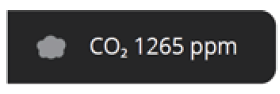
This icon is displayed on the screen in CO2 mode. If display function is turned on |
| Table 5. System Status Descriptions | ||
| State (Icon) | Icon Location | Description |

|
Home Screen |
When either of following error occur, this icon would be displayed.
• Some RTU compr. Locked • All RTU compr. Locked • RTU fault state – fault detected • CS fault state – fault detected |
 |
Home Screen |
Display during smooth setback recovery (SSR) execution. |
 |
Technician Status Screen |
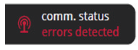
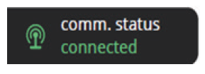
There are communication errors. |
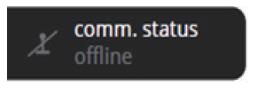 |
Technician Status Screen |
Lost communications with host. |
 |
Technician Status Screen |
There are no communication errors. |
 |
Technician Status Screen | When RTU state is warm-up mode coming out of an unoccupied state, this icon will be displayed. |
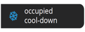 |
Technician Status Screen | When RTU state is cool-down mode coming out of an unoccupied state, this icon will be displayed. |
| Table 5. System Status Descriptions | ||
| State (Icon) | Icon Location | Description |
 |
Technician Status Screen |
Fresh air tempering heating. |
 |
Technician Status Screen |
Fresh air tempering cooling. |
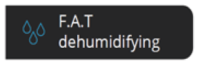 |
Technician Status Screen |
Fresh air tempering dehumidifying. |
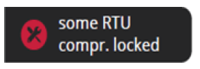 |
Technician Status Screen | This status is displayed when the RTU compressor has partially failed (or generates an error). |
 |
Technician Status Screen | This status is displayed when all RTU compressors have failed (or error occurred). |
 |
Technician Status Screen |
RTU faults detected. |
 |
Technician Status Screen |
No RTU faults detected. |
| Table 5. System Status Descriptions | ||
| State (Icon) | Icon Location | Description |
|
|
Technician Status Screen |
When the CS8500 (CS) has a fault state, this icon would be displayed.
The following possible errors may have occurred which would generate this system status: • Local temperature sensor error • External sensor error • Memory error • Humidity sensor error • CO2 sensor error |
 |
Technician Status Screen |
No faults detected |
Error Codes and Reminders
Any active history for notifications are listed under menu > notification. Press the down arrow icon next to the notification to expand the notification for further details. Press the contractor info option for assistance.
| Table 6. Error Codes and Reminders | ||||
| Condition | Issue | Display | System Action | Action to Clear / Recovery Condition |
|
Critical |
Built-In Temp Sensor error – temperature sensor reads -4°F or less or 158°F (+/- 5°F) or greater. |
Temperature Sensor Error |
• Indoor temp is displayed as “–” on the home screen.
• This error is displayed on the notification screen as well. |
• If the sensor starts detecting a normal operating range, the
error message will automatically clear and the system will return to normal operation. • Contact service contractor to replace the CS8500. |
|
Critical |
Remote temperature sensor error. External sensor reads -4°F or less or 158°F (+/- 5°F) or greater. |
External Sensor Error |
• Indoor temp is displayed as “–” on the home screen. • This error is displayed on the notification screen as well. • When configured for external temperature sensors and there is an error, the unit will automatically switch to the internal temperature sensor. |
• If the sensor starts detecting a normal operating range, the
error message will automatically clear and the system will return to normal operation. • Contact service contractor to replace the external temperature sensor. • Other than replacing the CS8500, go to the technician setting > temperature sensor config. and change the temperature sensor source back to internal temperature sensor. That will remove the error message from the home and notification screens. |
| Table 6. Error Codes and Reminders | ||||
| Condition | Issue | Display | System Action | Action to Clear / Recovery Condition |
|
Critical |
EEPROM error (power-on) |
Memory Error |
• System will restore all settings to factory default and resume operations.
• This error is displayed on the notification screen as well. |
Contact service contractor to replace the CS8500. |
|
Critical |
EEPROM error (operating) |
Memory Error |
• System will operate in normal mode until power off.
• This error is displayed on the notification screen as well. |
Contact service contractor to replace the CS8500. |
|
Critical |
Humidity sensor error (without Humidifier or Dehumidifier): Sensor reads out of range 0% to 100% |
Humidity Sensor Error |
• The reading for humidity is not valid. This message indicates humidity
sensor is not working correctly. When there is an error the home screen humidity display will indicate “–”. • This error is displayed on the notification screen as well. |
• Contact service contractor to replace the CS8500. • If the sensor starts detecting a normal operating range, the error message will automatically clear and the system will return to normal operation. |
| Table 6. Error Codes and Reminders | ||||
| Condition | Issue | Display | System Action | Action to Clear / Recovery Condition |
|
Critical |
CO2 Sensor error – sensor reads out of range (above 3500 ppm) |
CO2 Sensor Error |
• The reading for CO2 is not valid. This message indicates CO2 sensor is not working correctly.
• The display of Indoor CO2 from HOME will be “–”. • This error is displayed on the notification screen as well. |
• Contact service contractor to replace the CS8500. • If the sensor starts detecting a normal operating range, the error message will automatically clear and the system will return to normal operation |
|
Critical |
Comm error state at start-up. |
Comm Status – Errors Detected |
• When the failed (off- line) state is detected, continue listening for a valid message.
• If this occurs then normal operation should resume. • This error is displayed on the notification screen as well. |
• Contact service contractor to check communication wire connection. • If a valid message is received, then the error message will be automatically cleared and system will resume normal operations. |
|
Critical |
Some RTU compressors Locked |
Some RTU Compressors Locked |
This error is displayed in notification screen and technician system status screens. |
• User will have to contact the Service Contractor to have the system serviced.
• Will need to check RTU state • If the RTU recovered from the error automatically the error will also automatically clear. |
| Table 6. Error Codes and Reminders | ||||
| Condition | Issue | Display | System Action | Action to Clear / Recovery Condition |
|
Critical |
All RTU compressors Locked |
All RTU compressors Locked |
This error is displayed in notification screen and technician system status screens. |
• User will have to contact the Service Contractor to have the system serviced.
• Will need to check RTU state • If the RTU recovered from the error automatically the error will also automatically clear. |
|
Critical |
RTU Fault State Detected |
RTU Fault State Detected |
This error is displayed in notification screen and technician system status screens. |
• User will have to contact the Service Contractor to have the system serviced.
• Will need to check RTU state. • If the RTU recovered from the error automatically the error will also automatically clear. |
|
Reminder |
Routine system check up |
Routine system check up |
Displayed on notification screen. |
• Pressing clear button will clear the reminder.
• Or pressing remind later on pop-up screen will extend the duration. |
| Reminder | Custom reminder 1 |
User Editable |
Displayed on notification screen. |
• Pressing clear button will clear the reminder.
• Or pressing remind later on pop-up screen will extend the duration. |
|
Reminder |
Custom reminder 2 |
|||
| Table 6. Error Codes and Reminders | ||||
| Condition | Issue | Display | System Action | Action to Clear / Recovery Condition |
|
Minor |
Outdoor Temperature (RT17) Sensor Problem |
Outdoor Temp Sensor |
Displayed on notification screen. |
If measurement of the outdoor temperature sensor is out of specified range (including open
/ short detection, the alarm will be activated. Alarm will automatically clear once in range condition is detected. Check sensor and wiring. |
|
Minor |
Discharge (Supply) Air Temperature Sensor (RT6) problem. |
Discharge Air Temp Sensor |
Displayed on notification screen. |
If measurement of the discharge air temperature sensor is out
of specified range (including open / short detection, the alarm will be activated. Alarm will automatically clear once in range condition is detected. |
|
Minor |
Return Air Temperature Sensor (RT16) problem |
Return Air Temp Sensor |
Displayed on notification screen. |
If measurement of the return air temperature sensor is out of specified range (including open / short detection, the alarm will be activated. Alarm will automatically clear once in range condition is detected.
Check sensor and wiring. |
|
Minor |
Advanced Airflow Low Outdoor Airflow | Economizer Fault | Displayed on
notification screen. |
Outdoor airflow is too low so the building is not getting the designed outdoor airflow based on IAQ. |
|
Minor |
Advanced Airflow Outdoor Airflow Too High | Economizer Fault | Displayed on
notification screen. |
Ventilation CFM is too high so the RTU is wasting energy. |
| Table 6. Error Codes and Reminders | ||||
| Condition | Issue | Display | System Action | Action to Clear / Recovery Condition |
|
Minor |
Outdoor Air Damper Error (During Free Cooling) | Economizer Fault | Displayed on
notification screen. |
During free cooling damper is not modulating. |
|
Minor |
Not Economizing When Outdoor Air is Suitable | Economizer Fault | Displayed on
notification screen. |
May be due to the damper motor being unplugged
or disconnected. |
|
Minor |
Economizing When Outdoor Air is Not Suitable | Economizer Fault | Displayed on
notification screen. |
This may be due to damper motor being blocked or stuck open
and therefore not closing. |
REFERENCE:
Download Manual: Lennox CS8500 Commercial Programmable Thermostat
Lennox CS8500 Commercial Programmable Thermostat Installation and Setup Guide
Leave a Reply