
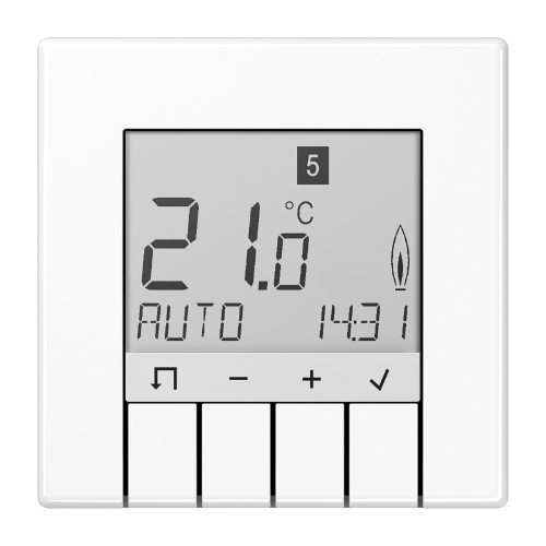
JUNG TR UD LS 231 WW Universal Room Temperature Thermostat
Safety instructions
The unit may only be opened by an electrician and installed according to the circuit diagram on the unit or in these instructions. Observe existing safety instructions.
To satisfy the requirements of protection class II, corresponding installation measures are required.
This independently installable electronic device is exclusively for controlling the temperature in dry, enclosed rooms with normal surroundings.
This device is in conformance with EN 60730 and functions according to operating mode 1C.
Damage to the device, fire, or other hazards may arise if these instructions are not followed.
These instructions are a component part of the product and must remain with the end customer.
Structure of the device
Fig. 1: Layout of the temperature controller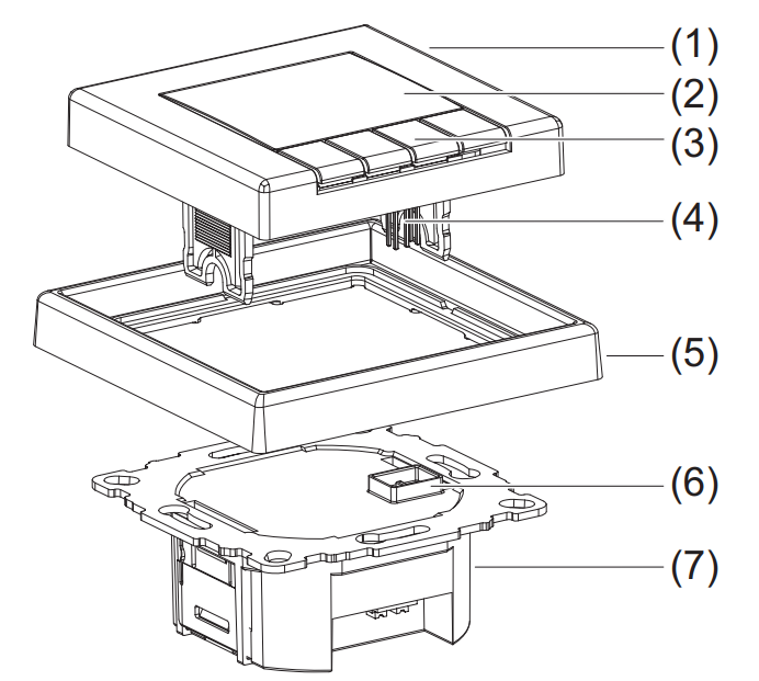
- Controls
- Display
- Control buttons
- Plug-in contacts
- Design frame (not including delivery)
- Socket for the plug-in contacts
- Use
Function
Correct use
- Measuring and controlling the room temperature
- Measuring and controlling the floor temperature
- Room temperature control via floor heating with a limiting function (for example in conjunction with tiled stoves)
- Can be used for “heating only” or “cooling only”
- Installable in a box in conformance with DIN 49073
- Only for use in dry, enclosed rooms
Product characteristics
- Large display with backlighting
- Text display for self-explanatory operation
- Programmable even when the controls are removed
- Different user languages can be selected
- Real-time clock with automatic switchover to/from daylight savings time
- Internal temperature sensor
- An external remote sensor can be connected
- Three selectable and adjustable time temperature programs for automatic mode
- A maximum of nine operating times per day (the setting can also be terminated after a specific operating time)
- Can be individually programmed every day, or a block of operating times can be set: workdays/non-workdays, all days the same
- Can be manually adjusted at any time
- “Vacation” mode with the entered date (from/to)
- “At-home” mode (present)
- Short-time timer (“party function”)
- Optimum start” function (the temperature is reached at the set time)
- Protection against frost
- Display of energy consumption for electric heating systems
- Pulse width modulation (PWM) or two-point control system
- Adjustable cycle time (PWM), hysteresis and minimum on/off time (two-point)
- Switch on delay, such as for burners (with two-point control)
- Adaptation to valves normally open or closed
- Valve protection (as a room temperature controller with and without a limiting function)
- Resetting separate from user and installer settings
Description of functions
The programmable temperature controller automatically controls the room or floor temperature depending on the time and day of the week. The automated program can be interrupted at any time by manual entries.
The temperature controller has three selectable programs for heating which can be adapted to your individual comfort. The controller is equipped with an internal sensor for measuring the room temperature. In addition, an external remote sensor can be connected, for example, to measure the floor temperature. The temperature controller compares the measured temperature with set values. If the temperature falls below the current setting, the heating system is turned on.
The control method depends on the type of heating and is determined by the installer: - Room temperature controller: The heating is turned on when the room temperature falls below the set target temperature (measured with an internal sensor or external remote sensor).
- Floor temperature controller: The floor heating is turned on when the floor temperature falls below the set target temperature (measured using an external remote sensor).
- Room temperature controller with a limiter (in conjunction with floor heaters):
The room temperature is measured and regulated using the internal sensor. An additional external remote sensor is connected to measure the floor temperature, and a target temperature range for the floor is set. The room temperature control is deactivated when the floor temperature is outside of this range. If the temperature falls below this range, the heater is turned on, and if the temperature is above this range, the heater is turned off independent of the current room temperature.
Operation
Fig. 2: Default display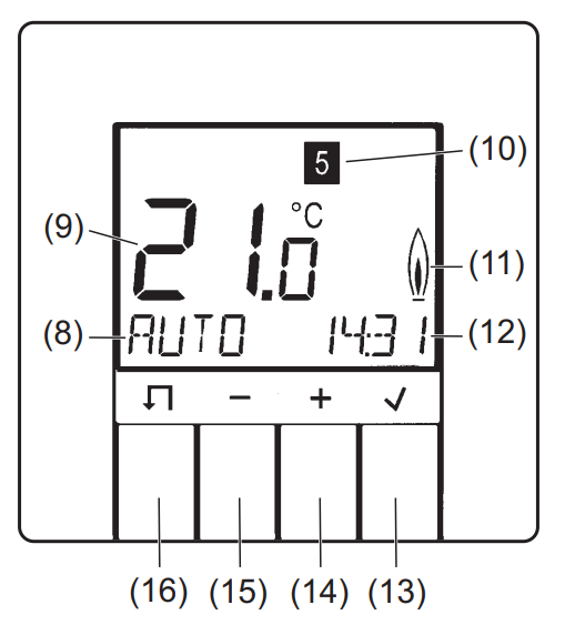
- Function display (such as the mode)
- Large display (such as the current temperature)
- Day of the week display
(1 = Monday … 7 = Sunday) - Heating mode display
- Display (such as the current time)
 BUTTON (info/OK)

 BUTTON MENU
Basic information
Four buttons below the display are used to operate the temperature controller (Fig. 2, items (13) to (16)). In the menu, you can activate operating modes, adapt programs and make settings. If a button is not pressed for more than three minutes, the unit automatically switches back to the previous function and the default display (Fig. 2). Program 1 and AUTO mode are the preselected defaults; see “Default programs” and “Modes and setting menus (overview 1)”.
Programming when the controls are removed
The unit can also be programmed when the controls are removed. The current temperature is not displayed, the “heating mode” display flashes, and the display is not illuminated. If a button is not pressed for more than three minutes, the display goes dark.
Display information on the current mode
To go to the default display when the controls are removed and the display is dark, press any button.
- Press in the default display.
Information on the current mode/setting is displayed in the form of a marquee. - Return to the default display by pressing .
Selecting modes and setting menus
- Press in the default display.
MENU briefly appears in the function display (8). A help text as a marquee appears at the bottom edge of the display.
Use the + / – buttons to switch to the desired mode/setting. - Select the desired mode/setting by pressing .
Another menu opens depending on the mode/setting.- Go back to the last display/setting by pressing .
- Go back to the last display/setting by pressing
- Return to the default display by pressingseveral times.
Manually adapting the target temperature
You can always adapt the target temperature in modes AUTO, MAN, and TIMER.
- In the default display, press + or -.
The current target temperature flashes. - Set the desired temperature by pressing + / -.
- Accept the displayed temperature by pressing .
The device returns to the default display.
Turning off the controls
- In the default display, press thebutton for 10 seconds.
- First “MENU” appears in the display. After 10 seconds, the device switches to the default display, and “OFF” appears.
- Turn the controls back on by selecting a mode.
Default programs
The controller offers three default time/temperature programs (full-day settings). These full-day settings depend on the selected heating mode (installer settings, H1) and can be selected by the user and adapted to individual heating preferences (user settings, G1 and G2). The factory setting is program 1.
The default time/temperature programs are illustrated in the following in sections in graphs and tables. A specific example is used (room temperature controller) for program 1 to explain the full-day settings.
Programs for room temperature controller with and without a limiting function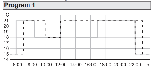
| Mon – Fri | Sat – Sun | |||
| Switching time | Time of day | T°C | Time of day | T°C |
| 1 | 06:00 | 21.0 | 07:00 | 21.0 |
| 2 | 08:30 | 18.0 | 10:00 | 18.0 |
| 3 | 12:00 | 21.0 | 12:00 | 21.0 |
| 4 | 14:00 | 18.0 | 14:00 | 21.0 |
| 5 | 17:00 | 21.0 | 17:00 | 21.0 |
| 6 | 22:00 | 15.0 | Sat, 23:00
Sun, 22:00 |
15.0 |
Full-day settings for program 1, room temperature controller
Program with six switching times. “Comfortable temperature” 21 °C, temperature lowered to 18 °C in the morning and afternoon of work days (absent) and lowered daily at night to 15°C.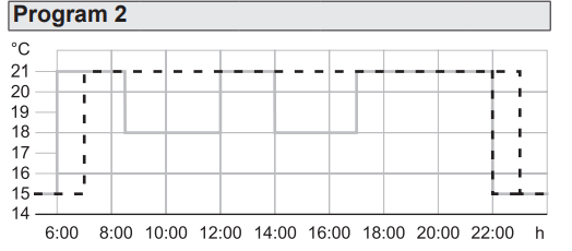
| Mon – Fri | Sat – Sun | |||
| Switching time | Time of day | T°C | Time of day | T°C |
| 1 | 06:00 | 21.0 | 07:00 | 21.0 |
| 2 | 08:30 | 18.0 | Sat: 23:00
Sun: 22:00 |
15.0 |
| 3 | 12:00 | 21.0 | ||
| 4 | 14:00 | 18.0 | ||
| 5 | 17:00 | 21.0 | ||
| 6 | 22:00 | 15.0 | ||
Table 2:
Full-day settings for program 2, room temperature controller.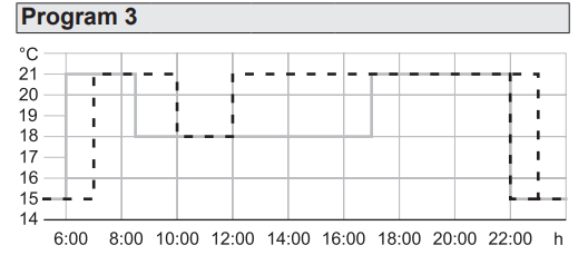
| Mon – Fri | Sat – Sun | |||
| Switching time | Time of day | T°C | Time of day | T°C |
| 1 | 06:00 | 21.0 | 07:00 | 21.0 |
| 2 | 08:30 | 18.0 | 10:00 | 18.0 |
| 3 | 17:00 | 21.0 | 12:00 | 21.0 |
| 4 | 22:00 | 15.0 | Sat, 23:00
Sun, 22:00 |
15.0 |
Table 3:
Full-day settings for program 3, room temperature controller.
Programs for the floor temperature controller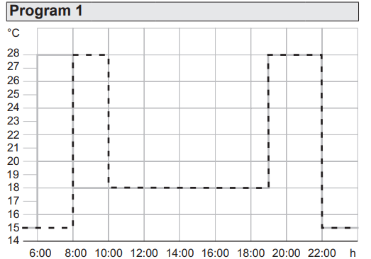
|
Mon – Fri |
Sat – Sun |
|||
| Switching time | Time of day | T°C | Time of day | T°C |
| 1 | 06:00 | 28.0 | 08:00 | 28.0 |
| 2 | 08:00 | 18.0 | 10:00 | 18.0 |
| 3 | 19:00 | 28.0 | 19:00 | 28.0 |
| 4 | 22:00 | 15.0 | 22:00 | 15.0 |
Table 4: Full-day settings for program 1, floor temperature controller.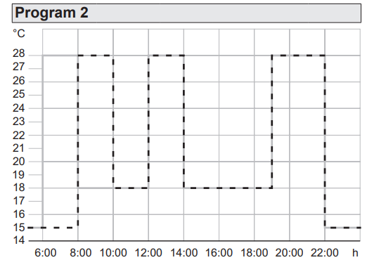
| Mon – Fri | Sat – Sun | |||
| Switching time | Time of day | T°C | Time of day | T°C |
| 1 | 06:00 | 28.0 | 08:00 | 28.0 |
| 2 | 08:00 | 18.0 | 10:00 | 18.0 |
| 3 | 12:00 | 28.0 | 12:00 | 28.0 |
| 4 | 14:00 | 18.0 | 14:00 | 18.0 |
| 5 | 19:00 | 28.0 | 19:00 | 28.0 |
| 6 | 22:00 | 15.0 | 22:00 | 15.0 |
Table 5: Full-day settings for program 2, floor temperature controller.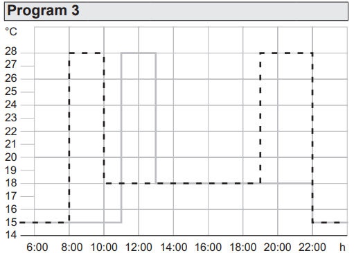
|
Mon – Fri |
Sat – Sun |
|||
| Switching time | Time of day | T°C | Time of day | T°C |
| 1 | 11:00 | 28.0 | 08:00 | 28.0 |
| 2 | 13:00 | 18.0 | 10:00 | 18.0 |
| 3 | 22:00 | 15.0 | 19:00 | 28.0 |
| 4 | 22:00 | 15.0 | ||
Table 6: Full-day settings for program 3, floor temperature controller.
Select program (G1)
The factory setting is program 1.
The device is in the default display.
Press the M button.
The help text “MENU…” appears at the bottom edge of the display.
- Press + / – to select the settings menu USER SETTINGS and confirm with .
G1 – PROGRAM SELECT ONE appears.
Press the O button.
The number of active programs flashes. - Press + / – to select the desired program (1 … 3) and confirm with .
G1 – PROGRAM SELECT ONE appears. The selected program is now active.
Adapting the program (G2)
The default programs can be adapted to individual heating comfort. A maximum of 9 switching times/intervals per day is possible. All adaptations affect the active program. When you switch to the new program, the adaptations are not saved; that is, any adaptations made to a default program must be reconfigured.
The desired program is active (G1), and G1 – PROGRAM SELECT ONE appears.
- Press the + button.
G2 – EVENT SETTING appears. - Press to select menu item G2.
DAY is displayed, and the day of the week display (10) flashes.
The numbers correspond as follows: 1 Monday, 2 Tuesday… 7 Sunday.
With the exception of individual weekdays, switching times can also be set for blocks of days 1-5, 6-7, 1-7.
- Press + / – to select the desired day/block of days, and confirm with .
The temperature display (9) for the first switching interval of the day flashes. - Press + / – to set the desired temperature and confirm with .
The starting time of the switching interval flashes. - Press + / – to set the desired start time and confirm with .
The ending time of the switching interval flashes. - Press + / – to set the desired ending time and confirm with .
The first switching interval is now set. The temperature display for the second switching interval flashes.
If needed, additional temperatures and switching times can be set using the same procedure. The number of the switching interval is displayed in the bottom line of the display in front of the switching times. The respective end time in the display becomes the start time of the next interval. Each switching time can be decreased to the previous time or to 00:00 and increased to a maximum of 23:50. If ->>> flashes in the display, the following switching time falls within the next weekday.
- Press to go to the first start time of the next day of the week.
- Press + / – to create a different switching interval.
If all 9 switching times of the day are already assigned, the program automatically jumps to the next day of the week. You can delete a switching interval indirectly by increasing the previous interval. Repeatedly press![]() to leave menu item G2 – EVENT SETTING. The settings take effect.
to leave menu item G2 – EVENT SETTING. The settings take effect.
Modes and setting menus (overview 1).
To follow is an overview of the modes and setting menus within the main menu.
| AUTO |
| Automatically control the room temperature ac- cording to the time and temperature settings of the selected program. Adapt the temperature to the next switching time (see “Manually adapt the target temperature”). A minus sign following the “AUTO–” mode in the display indicates that the target temperature has been adapted and that it deviates from the temperature saved in the time/temperature program until the next switching time. |
| MAN |
| Manually control the room temperature independent of the time to the value set here (see “Manually adapt target temperature”.) |
| TIMER |
| Short-time timer to specify the room temperature for a set number of hours (“Party function”). • Press +/ – to set the hours and confirm with O. •Press +/ – to set the temperature and confirm with O. The display (12) shows the number of remaining hours. Subsequently adapt the temperature for the remaining hours (see “Manually adapt the target temperature”). |
| HOLIDAY |
| Specify a room temperature for a set time interval with the start and end date of the vacation. Until vacation starts, the currently set mode is active: AUTO, MAN, TIMER, AT HOME. Start HOLIDAY when the start date is reached. Set the year, month, and day for the first and last day of vacation with +/ – and confirm with O. •Press +/ – to set the temperature and confirm with O.”V.” and the date of the last day of vacation is shown in the displays (8) and (12). |
| AT HOME |
| Control the temperature independent of the day of the week according to the time and temperature information in the selected program (full-day setting). The program defaults correspond to the current day program of Monday.
• Set the temperature and switching times with +/ – and confirm with |
| USER SETTINGS |
| Open the menu for the user settings. The display (9) shows the menu ID G1. •To select the desired submenu, see “User settings”. |
| INSTALLER SETTINGS |
| Open the setting menu for the installer. The display (8) shows the menu ID H1. •To select the desired submenu, see “Installer settings”. |
Overview 1: Modes and setting menus
Select the desired mode/setting menu
The device is in the default display.
- Press the M button.
The help text “MENU…” appears at the bottom edge of the display. - Press the buttons + / – until the desired menu item (mode or set menu) appears.
- Confirm with .
The function is activated in modes AUTO and MAN.
With the other menu items, the device jumps to additional settings (see overview 1).
User settings
Overview 2
A marquee at the bottom of the display shows information for individual menu items identified with G1 to G16.
Depending on the set control procedure, the menu items G11 and G12 are not available. (The menu displays and set all values in UPPERCASE, and the settings are bold).
| G1 | PROGRAM SELECT ONE |
| Choose one of the default time/temperature pro- grams (see “Select program”): 1, 2, 3. Select the program number with +/ -, and confirm with |
|
| G2 | EVENT SETTING |
| Adjust a default time/temperature program (see “Adapt program”): Adjust the days of the week, temperatures, switch- ing times with +/ -, confirm with |
|
| G3 | CLOCK SETTING |
| Set the date and time.
Set the YEAR, MONTH, DAY, HOUR, and MINUTE with +/ – and confirm with |
|
| G4 | OFF HEATING PERMANENT |
| Turn off the temperature control:
– YES = Control off Select YES/NO with +/ -, and confirm with If OFF HEATING PERMANENT = YES is selected, the frost protection is actively provided that it has been set by the installer, see also Installer settings H6 – FROST PROTECTION ≠ OFF Display function (8): OFF |
|
| G5 | SUMMER/WINTER TIME CHANGE |
| Set whether the switchover from/to daylight savings is automated.
– YES = automated |
|
| G6 | KEY LOCK |
| Protect the controller from unauthorized use. Use is not possible when access protection is enabled. – YES = access protection on – NO = no access protection Select YES/NO with +/ -, and confirm with |
|
| G7 | TEMP LIMIT MIN/MAX TEMP |
| Set the bottom and top temperature to be regulated: – LOWER TEMP LIMIT: For the room temperature controller (H1 = ROOM or LIMITER): 5.0°C, 5.5°C … 30.0°C For the floor temperature controller (H1 = FLOOR): 10.0°C, 10.5°C … 40.0°C – UPPER TEMP LIMIT: For the room temperature controller (H1 = ROOM or LIMITER): 5.0°C, 5.5°C … 30.0°C For the floor temperature controller (H1 = FLOOR): 10.0°C, 10.5°C … 40.0°C Set the temperatures with +/- and confirm with O |
|
| G8 | COSTS /HR OF ENERGY |
| Enter the estimated energy costs per hour for the room in which the temperature is being controlled: 1, 2, … 100 … 999 CENT/HR. If the energy cost meter is to serve as an operating hour meter, set the value COST/h to 100. Set COST/HR with +/ -, and confirm with |
|
| G9 | ENERGY CONSUMTION TO DATE |
| Display of the approximate energy consumption in euros (or operating hours) per time period. The current day is included up to the displayed time.
Calculation: Time heat turned on x COST/HR (G8). EURO/2 DAYS, EURO/WEEK, EURO/30 DAYS, EURO/YEAR. |
|
| G10 | SET TEMP TO READ |
| Setting for the target temperature to be shown in the display instead of the current room temperature:
– YES = Target temperature – NO = Room temperature Select YES/NO with +/ -, and confirm with |
|
| G11 | ADJUST TEMP |
| This menu item is not available when used as a floor temperature controller. Specify a correction value to be displayed and regulated: -5.0°C, -4.9°C … 0.0°C….. 4.9°C, 5.0°CUseful adaptations are for example matching calibrated thermometers, or adapting to install- location heights or locations that are problematic. Adjust the correction value with +/- and confirm with . |
|
| G12 | NUMBER FOR FLOOR TEMP |
| W This menu item is not available when used as a room temperature controller with/without a limiting function.
Activate the floor temperature display for information (without the unit °C). |
|
| G13 BACKLIGHT | |
| Set the display lighting: – SHORT = short time after pressing the button – OFF = always off – PERMANENT (only when using a remote sensor) Select SHORT/OFF or PERMANENT with +/ -,confirm with . |
|
| G14 | LANGUAGE |
| Select the languages shown in the display: GERMAN, ENGLISH, DUTCH, FRENCH Select the LANGUAGE with +/ -, and confirm with . |
|
| G15 | INFO |
| Display controller type and controller version: TR UD … Display the controller version with +/ -, and go back to the menu with |
|
| G16 | RESET USER SETTINGS ONLY |
| Reset the user settings to the defaults.
W The counter ENERGY CONSUMTION TO DATE is not reset. This is reset by the installer in the menu H9. |
|
Overview 2: User settings
Open the settings menu and make the settings
The menu ID G1 appears in the display (9), and PROGRAM SELECT ONE appears at the bottom as a marquee.
- Press + / – o to select the desired menu.
The menu ID and a help text appear at the bottom edge of the display (8) and (12). - Confirm with .
The first settable value flashes in the display. - Set the desired value by pressing + / -.
- Confirm with .
The next settable value flashes in the display.
Once all the values are set, the display returns to a higher level and displays the menu ID.
Information for electrically skilled persons
Installation and electrical connection
DANGER!
Electric shock from touching live parts.
Electric shock can be fatal.
Before working on the device, disconnect the connecting lines and cover the surrounding live parts.
Installation site
The controller should be installed at a location in the room that is easily accessible for use.
When using the internal temperature sensor, the chosen installation site should:
- Enable free circulation of air
- Not be in a draft (such as an open window or doors)
- Not be located behind curtains, cabinets, shelves, etc.
- Not be exposed to direct sunlight
- Not be directly influenced by sources of heat
- Not be adjacent to external walls
- Be 1.5 m above the floor.
Connecting and installing the controller.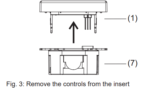
- Remove the controls (1) from insert (7).
- Remove a maximum of 8 mm of insulation from the connecting lines.
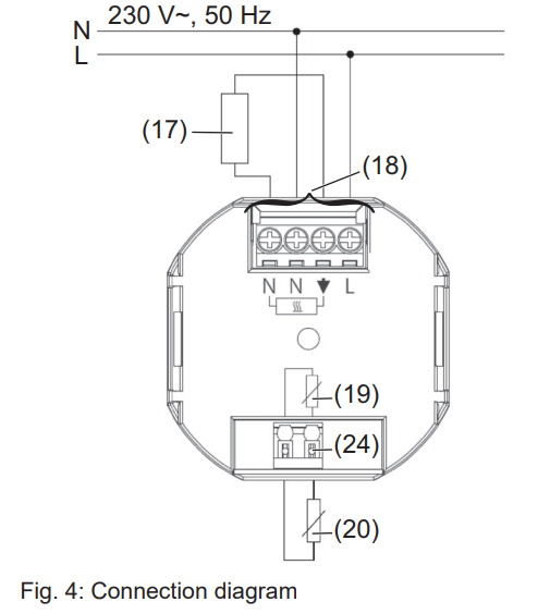
The terminals (18) before the power supply and switching current are designed for solid or flexible lines with a cross-section of 1 to 2,5 mm2.
- Connect the controller according to the connection diagram (Fig. 4).
- If necessary, connect an external remote sensor (20) (see “Connecting the external remote sensor”).
Only install the temperature controller in non-conductive plastic flush-mounted boxes with a diameter of 60 mm.
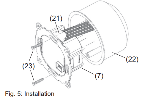
- Align the insert (7) in the receptacle (22).
- Fix the insert with fastening screws (23). Install the insert so that the plastic tongue (21) functions as insulation against the fastening screw (Fig. 5).
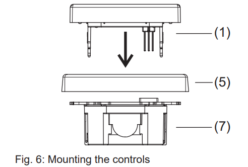
- Mount the design frame (5) and secure it by attaching the controls (1).
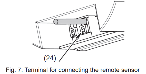
Connecting the remote sensor
An external remote sensor is necessary for the modes “Floor temperature controller” and “Room temperature controller with limiter”. The remote sensor line carries mains voltage and can be extended to 50 m with appropriate wires. In order to prevent signal faults, do not run the remote sensor line together with the power lines. It is recommendable to run the remote sensor in ducting.
- Connect the remote sensor according to the connection diagram (Fig. 4, item (20)).
- When inserting and removing the connecting line using an appropriate tool, press the release button (Fig. 4/7, item (24)).
Start-up
CAUTION!
The heating system will malfunction if the controls are incorrectly set.
This can damage the heating system.
Only a technician may adjust the settings.
Set the heating mode when starting the controller.
- Press in the default display.
MENU briefly appears in the function display (8). A help text as a marquee appears at the bottom edge of the display. - Press the + / – buttons until INSTALLER SETTINGS appear.
- Select INSTALLER SETTINGS with O.
CODE is displayed, and code number 0 flashes. - Select code 7 with + / -, and confirm with O. H1, and the marquee text APPLICATION is displayed. Press .
ROOM is the default. When switching the heating mode, all of the user and installer settings are reset to the default.
- Press + / – to set the desired heating mode and confirm with.
The heating mode is set.
Additional settings are available under “Installer settings”.
Installer settings
Overview 3
A marquee at the bottom of the display shows information for individual menu items identified with H1 to H11.
Some menu items are not available under the control modes set under H1.
The abbreviations for the relevant control mode for each menu item are indicated in the table.
The abbreviations have the following meaning:
- R = Room temperature controller
- F = Floor temperature controller
- L = Room temperature controller with a limiting function
(The menu displays and set all values in UPPERCASE, and the settings are bold)
| H1 APPLICATION | R | F | L |
| Selection of the control method depending on the heating mode: – ROOM = Room temperature controller with the setting of whether or not a remote sensor is connected: EXTERN SENSOR = YES/NO – FLOOR = Floor temperature controller – LIMITER = Room temperature controller with limiter Select +/ -, and confirm with . |
|||
| H2 CONTROL MODE | R | F | L |
| Select the control mode: – PWM = Pulse width modulation with the cycle time set in minutes: 10, 15 … 30. For fast heating systems, select a short cycle time, for slow heating systems, select a long cycle time. The minimum on/off time is 10% of the cycle time. – ON/OFF= two-point control with adjustable hysteresis (OFF, 0.1°C, 0.2°C … 5.0°C) and minimum relay on/off time in minutes (1, 2 … 10 … 30). If the hysteresis is not set, the relay switches with the minimum on/off time even when the temperature differences are very small. Select +/ -, and confirm with . |
|||
| H3 MIN/MAX FLOOR TEMP | L | ||
| Setting the top and bottom limit for the floor temperature: – LOWER TEMP LIMIT: The floor should not be colder than the set temperature (OFF, 10.0°C, 10.5°C … 35.0°C). – UPPER TEMP LIMIT: The floor should not be warmer than the set temperature (OFF, 10.0°C, 10.5°C … 35.0°C…. 40.0°C, OFF). Set the temperatures with +/- and confirm with To deactivate the top or bottom limit, set the bottom temperature limit < 10°C, or the top temperature limit > 40°C with + / –. OFF is displayed. |
|||
| H4 HEATING OR COOLING | R | ||
| Switching the controller between heating and cooling modes: – HEATING – COOLING Precondition for switching to cooling mode: H2 – CONTROL MODE = ON/OFF When switching to cooling mode, H6 – FROST PROTECTION is automatically set to OFF, and H7 – OPTIMUM START is set to NO. The switching times and temperatures of the heating mode are used. Select +/ -, and confirm with |
|||
| H5 VALVE PROTECTION | R | L | |
| Protection of the valve from seizing after long periods of nonuse. The valve is opened at 10 o’clock every day for the time in minutes set here: OFF, 1, 2, 3 … 10. Set the opening time with +/ – and confirm with |
|||
| H6 FROST PROTECTION | R | F | L |
| Setting the frost protection temperature: – For H1 = ROOM or LIMITER:
OFF, 5.0°C, 5.5°C … 30.0°C |
|||
| H7 OPTIMUM START | R | F | L |
| This setting causes the system to go to the set target temperature upon starting: – YES = OPTIMUM START – NO AUTO_ is displayed in the required preheating time. Select YES/NO with +/ -, and confirm with |
|||
| H8 VALVES NORMALLY OPEN | R | L | |
| The reverse of the relay switching behavior for using actuators that are normally open: – YES = activated – NO = deactivated Select YES/NO with +/ -, and confirm with . |
|||
| H9 ENERGY COUNTER RESET | R | F | L |
| Reset zero the energy cost meter set under G8/ G9 (see user settings). – YES = reset – NO Select YES/NO with +/ -, and confirm with . |
|||
| H10 FLOOR TEMPERATURE DISPLAY | L | ||
| Display the current floor temperature for service purposes. | |||
| H11 RESET ALL | R | F | L |
| Reset to the defaults all of the settings made in the menus for the installer and user.
– YES = reset – NO Select YES/NO with +/ -, and confirm with |
|||
Open the settings menu and make the settings
The menu ID H1 appears in the display (8), and APPLICATION appears at the bottom as a marquee.
- Press + / – o to select the desired menu.
The menu ID and a help text appear at the bottom edge of the display (7) and (11). - Confirm with .
The first settable value flashes in the display. - Set the desired value by pressing + / -.
- Confirm with .
The second settable value flashes. - Repeat the aforementioned steps until all the values are set.
The display returns to a higher level and displays the menu ID.
Appendix
Do not dispose of this product in household garbage. Dispose of the device in a facility designated for electronics waste. Consult the local recycling authorities.
This symbol confirms that the product is in conformance with the relevant guidelines.
Technical data
- Operating voltage: AC 230 V ~
- Rated frequency: 50 Hz
- Output: Make contact relay, non-floating
- Switching current: 10 mA … 16 (4) A, 230 V~
- Power consumption: ~ 1.2 W
- Degree of protection: IP 30
- Protection class: II (with the corresponding installation)
- Pollution category: 2
- Ambient temperature:
- operation: 0°C to 40 °C (without thawing)
Storage: -20°C to 70°C (without thawing)
- operation: 0°C to 40 °C (without thawing)
- Temperature setting range (in increments of 0.5 °C):
- as a room temperature controller: 5°C … 30 °C
- as a floor temperature controller 10°C … 40 °C
- Temperature display: in increments of 0.1°C
- Output signal: Pulse width modulation (PWM) or two-point control ( on/off)
- PWM cycle time: adjustable (10 … 30 min)
- Hysteresis: adjustable (with two-point control)
- Minimum switching time adjustable (1 … 30 min)
- Rated impulse voltage: 4 kV
- Temperature for the ball thrust test: 75 ± 2°C
- Voltage and current for the EMC emitted interference test: 230 V, 0.1 A
- Software class: A
- Accuracy: < 4 min/year
- Reserve power: ~ 10 years (lithium cell)
Help in case of problems
Overviews 4 and 5 describe a few error messages and problems as well as probable causes and solutions.
Error message/problem
Possible cause: Suggestions for troubleshooting
Display of device faults
Errors in the hardware configuration can be shown on the display. In this case, ERR and an error type are displayed as marquee text.
| ERR CONFIGURATION |
| The controls and insert do not match.
– Only use matching components. – Turn the power off and on. |
| ERR COMMUNICATION |
| Communication problem between the controls and insert.
– Remove the controls and put them back on. – Turn the power off and on. |
| ERR EXT SENSOR |
| External remote sensor is broken/shorted/missing.
– Check whether the remote sensor is connected. The limits of the display range are exceeded. – Determine the cause and eliminate it. |
Overview 4: Display of device faults
Other problems and operating errors
| The heating takes too long. |
| The programmed switching times or times are incorrect. – Adapt programming (G1, G2). The time switched to/from daylight savings. – Adapt the time (G3, G5). The optimum start is deactivated or does not run long enough (a few days) in order to determine the optimum preheating time. – Select the optimum start (H7) and give the controller time to adjust to the surrounding conditions. |
| The room is heating up too slowly. |
| The floor temperature is limited by the maximum limiter. – Deactivate the upper limit (H3). |
| The room temperature is too hot. |
| The floor temperature is limited by the minimum limiter.
– Deactivate the bottom limit (H3). |
| No entries can be made. |
| Access protection is enabled. – Disable access protection (G6). |
| The desired temperature cannot be set. |
| The temperature limitation prevents the desired setting. – Reset the temperature limitation (G7). |
| The temperature display does not change. |
| The target temperature display is activated. – Enable the display of the room temperature (G10). |
Overview 5: Other problems and operating errors
ACCESSORIES
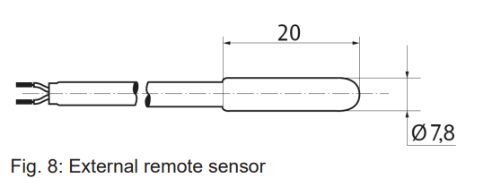
Remote sensor (not included in the delivery)
The external sensor must meet the requirements of protection class II.
Please use sensor cable H03VV-F for installation in the protection tube or H05VV-F without the protection tube.
- Type: FF 7.8
- Length: 4 m (can be extended up to 50 m)
- Wire: flexible, finely stranded
- Stripped end: 8 mm
Resistance/temperature table for remote sensor FF 7.8
| Temperature [°C] | Resistance [kn] |
| 10 | 66.8 |
| 20 | 41.3 |
| 25 | 33 |
| 30 | 26.3 |
| 40 | 17.0 |
| 50 | 11.3 |
Table 7: Resistance/temperature table for remote sensor FF 7.8
Warranty
The warranty is provided in accordance with statutory requirements via the specialist trade.
Reference
Download manual:
JUNG TR UD LS 231 WW Universal Room Temperature Thermostat Operational Manual
![]()
JUNG TR UD LS 231 WW Universal Room Temperature Thermostat Operational Manual
Leave a Reply