
Hotowell HTW-81-FN7W Smart Wifi Multi Stage Thermostat
App Name
Specifications
- Power Supply: AC24V 50/60Hz
- Self-consumption: 2W
- Dimensions: 5.35×3.7×1.02’’(136x94x26mm)
- Output Ampere: 1A (Resistive load)
- Sensor: NTC Sensor
- Temperature setting range: 5~37℃ n(41~98.6F)
- Accuracy: ±0.5℃
- Material: Toughened glass + PC
- Wiring: By terminals
- Mounting size: 2.36’’(60mm) or 3.23’’(82mm)
- Certificate: FCC
WARNING
READ CAREFULLY – These instructions will help prevent difficulties that might arise during thermostat installation and operation. Studying the instructions first may save considerable time and money later. Observing the following procedures will keep installation time to a minimum. Save these instructions for future use
FUNCTIONS AND FEATURES
This thermostat has been designed to control conventional heating and cooling system or heat pump system.
- Compatible with Google home & Amazon Echo
- 4.3’’ LCD screen clear display
- White bright digits
- Touch sensitive buttons
- White backlit display
- Apps for IOS and Android devices
General
HTW-81-FN7WF smart thermostat combines user-friendly touch sensitive buttons with WiFi wireless smart control application, offering unparalleled user control. Its local efficient control system and remote wireless smart control save up to 32% heating & cooling cost. Local energy-saving programmable solution for providing highly accurate temperature control. Remote wireless control through the application for providing easy and comfortable life style. Program a full 7 days schedule or change the settings through the App for total room control. The Apps support Google home and Amazon echo for good human-machine communication.
Installation
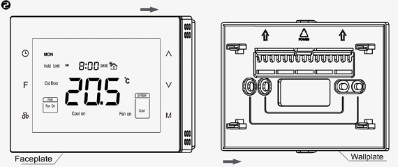
- Step 1 Separate the installation plate from thermostat by pulling it apart and holding point A and B(or use a screw driver to pry the 4 latches as left directions ). Insert the wires into the corresponding terminals according to the diagram and fasten the wall plate to a mounting box with the provided M*25mm screws. Ensure the proper orientation of the wall plate with the arrows on it pointing Up as shown on the left.
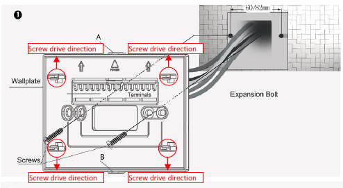
- Step 2 Check all the wires and then evenly push the face plate into the wall plate till the wall plate and the face plate fit tightly
Wiring Diagram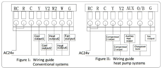
Terminals Explanation
| Terminals | Explanation | Remark |
| RC | Cooling power (two transformers) | Joined with R by jumper (one transformer) |
| R | Heating power (two transformers) | Joined with RC by jumper (one transformer) |
| W (O/B) | Heat output | Changeover valve output (heat pump) |
| Y | Cool output | Compressor output (heat pump) |
| G | Fan output | Blower Output |
| C | 24VAC common | Connect only when AC power |
| Y2 | Cool output 2 | 2nd stage compressor output (heat pump) |
| W2(AUX) | Heat output 2 | Auxiliary heat output (heat pump) |
Wiring Instructions
| No. | Type | Terminals | Wiring | Compressor delay |
| 0.0 | 1H/1C (conventional) | R、G、W、Y |
Diagram conventional systems |
none |
| 1.0 | 1H/2C (conventional) | R、G、W、Y、Y2 | none | |
| 2.0 | 2H/2C (conventional) | R、G、W、Y、W2、Y2 | none | |
| 3.0 | 2H/1C (conventional) | R、G、W、Y、W2 | none | |
| 4.0 | 1H/1C (heat pump) | R、G、O/B、Y |
Diagram heat pump systems |
1 min (default) |
| 5.0 | 2H/1C (heat pump) | R、G、O/B、Y、AUX | 1 min (default) | |
| 6.0 | 2H/2C (heat pump) | R、G、O/B、Y、Y2 | 1 min (default) | |
| 7.0 | 3H/2C (heat pump) | R、G、O/B、Y、AUX、Y2 | 1 min (default) |
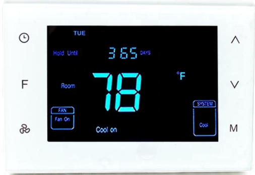
Display and Buttons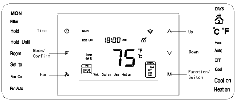
Wi-Fi Network Configuration
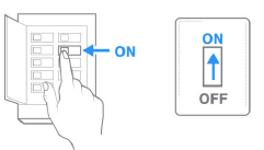
- Step 1: Power on the thermostat
- Tap “F” button switch to “Hold”or “Hold Until” Mode
- Step 2: Make sure it runs in Until” Mode then Press
 for 3 seconds until “E” then press M to confirm
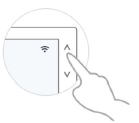
- Step 3: Press
 to make the screen display -E-, then press M to confirm
 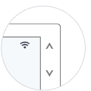 Step 4: For the following operation, please refer to the instruction indicated on the App.
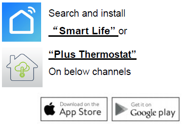
Download APP
Search “Smart Life” or”‘Plus Thermostat’ from App Store or Google Play to download the APP.
APP Account Management
Register an account number with the mobile phone number or e-mail address. Share user rights to others who have registered in the APP
Operation Instructions
Switch ℃ /℉
In normal display interface, press ![]() F button synchronically for at least 3 sec to switch between ℃ and ℉. (only available in Programming mode Not available in Hold or Hold Until Mode.) Tips:Tap “F” button switch among Programming-Hold-Hold Until
F button synchronically for at least 3 sec to switch between ℃ and ℉. (only available in Programming mode Not available in Hold or Hold Until Mode.) Tips:Tap “F” button switch among Programming-Hold-Hold Until
Set time
Press & hold for 3 sec to enter into the interface for the local time setting. First, 00-year flashes (0~99 indicates 2000~2099 year), press
 ![]() to modify the values, then press to switch to 01 months, month value flashes, press to modify the values, then press to switch to 02 day, day value flashes, press to modify the values, then press to switch to 03 hour, hour value flashes, press to modify the values, then press to switch to 04 minute, minute value flashes, press or to modify the values. Continually press, it will switch among Year-Month-Day-Hour-Minute. Press F to save the status then back to the temperature setting interface, “ ” displays and temperature value flashing, then press to modify the value, press F or wait for the delay time end, and return back to the normal display. (Local time can not be set in Hold Until mode
to modify the values, then press to switch to 01 months, month value flashes, press to modify the values, then press to switch to 02 day, day value flashes, press to modify the values, then press to switch to 03 hour, hour value flashes, press to modify the values, then press to switch to 04 minute, minute value flashes, press or to modify the values. Continually press, it will switch among Year-Month-Day-Hour-Minute. Press F to save the status then back to the temperature setting interface, “ ” displays and temperature value flashing, then press to modify the value, press F or wait for the delay time end, and return back to the normal display. (Local time can not be set in Hold Until mode
Set mode
In normal display interface, press slowly to switch among “Heat, OFF, Cool & Auto”. After the state change, “ ” displays and temperature value flash for 5 sec. Users can choose to change the value for temperature setting. If not, press F twice to save the change and return to normal display. (Changed value only valid in this current Schedule, and will lose if Schedule, system state changes or power off) OFF: In this state, Heating, Cooling and Fan will all forced close. Displays keep on.
Auto: In this state, a constant temperature will be kept. Device will activate/ stop heating/cooling system automatically according to the setting and room temperature.
Conventional system
Heat
- Room temp.≤Setting temp.-1℃ “Heat on” displays and 1st stage heating system is on;
- Room temp.≤Setting temp.-2℃ “Heat on”& “AUX” display and 2nd stage heating system is on; (not available for 1 stage heat system)
- Room temp.≥Setting temp., heating system stops and “Heat on” disappears from screen.
Note: 2nd heat stops and “AUX” disappears when temp. difference is less than 1 ℃.
Cool
- Room temp.≥ Setting temp.+1 ℃ “Cool on” displays and 1st stage cooling system is on;
- Room temp.≥ Setting temp.+2 ℃ “Cool on” stays and 2nd stage cooling system is on ; (not available for 1 stage cool system)
- Room temp.≤ Setting temp., cooling system stops and “Cool on” disappears from screen.
Note: 2nd cool stops when temp. difference is less than 1 ℃.
Heat pump system
- Heat (Changeover valve keep closed)
- Room temp.≤Setting temp.-1℃ “Heat on” displays and 1st stage heating system is on;
- Room temp.≤Setting temp.-2℃ “Heat on” stays and 2nd stage heating system is on;
- Room temp.≤Setting temp.-3℃ “Heat on”& “AUX” display and Aux heating system is on;
- Room temp.≥Setting temp., heating system stops and “Heat on” disappears from screen.
Note: Aux heat stops and “AUX” disappears when temp. difference is less than 2 ℃. 2nd heat stops when temp. difference is less than 1℃
- Cool (Changeover valve keep open)
- Room temp.≥ Setting temp.+1 ℃, “Cool on” displays and 1st stage cooling system is on;
- Room temp.≥ Setting temp.+2 ℃, “Cool on” stays and 2nd stage cooling system is on;
- Room temp.≤ Setting temp., cooling system stops and “Cool on” disappears from screen.
Note: 2nd cool stops when temp. difference is less than 1℃
Compressor protection
After an operation of heating/cooling system, there is a 1 min compressor off time to protect compressor. “Wait” will display on the screen if next operation is activated within the 1 min period.
Fan mode setting
- Press to switch among “Fan on & Fan Auto”.
- Fan on: Fan is always on.
- Fan Auto:Fan runs automatically only when heating/cooling system is on.
- (If system is in OFF state, the fan will always off)
Mode setting
Press F to switch among “Schedule, Hold & Hold Until (Holiday)” modes.
Programmable Schedule(Programming)
- Any icon
 from stands for one time period, and there are 4 periods that can be set in one day. Under the time setting mode, press to enter into time setting interface, the time parameter of cooling or heating mode can be set. Press then switch among 7 days → 5+2 days → a whole week: [ MON→TUE→WED→THU→FRI→SAT→SUN→(MON TUE WED THU FRI)→(SAT SUN)→(MON TUE WED THU FRI SAT SUN) ].
When setting the parameters, press F to exit to the modify interface, then get back to the temperature setting interface.
- Press then press to change the flashing hour, minute & temperature value of the chosen day and time period (changes in 15 minutes at a time);
- After completed the time setting, Press M switch to the temperature setting, setting temperature flash and press or to modify the setting temperature.
- After finished the above steps, press M to switch to the 2nd period of Monday and repeat item 1 and 2 steps, then complete 4 periods of Monday setting. Press to save and enter schedule setting for the following day.
The below table is the time parameter setting in different modes: (Factory Default)
|
Periods |
Time |
Parameters |
Fan |
|
| Heating | Cooling/ Auto | |||
| 1 | 06:00 | 21.0℃ | 25.5℃ | Fan on |
| 2 | 08:00 | 16.5℃ | 29.5℃ | Fan on |
| 3 | 18:00 | 21.0℃ | 25.5℃ | Fan on |
| 4 | 22:00 | 16.5℃ | 28.0℃ | Fan on |
Hold
This mode comes after “Schedule” by pressing F. In this mode, the device will keep a constant temperature until the next change.
- “Hold” & “ ” display and temperature value flashing. The press can change the value, and press F to save the setting;
- Press M can set system state;
- Press
 can set fan mode.
Hold Until (Holiday)
This mode comes after “Hold”by pressing F again. In this mode, device will follow the setting temperature and lasting days when users are out for a holiday. And then back to follow Schedules after the holiday.
- “Hold Until” & “ ” display and temperature value flashing. Press can change the value, and press F to save the setting. Then days value flashing, users can choose from 1-180 days by pressing or ;
- Press M can set system state;
- Press can set fan mode.
Override temperature setting
During any Schedule period, press can enter an interface for temperature setting. Press to change setting temperature, and press F to save the change. The changed setting only valid in the current Schedule period, device will follow the original schedule in next period.
Filter cleaning reminder
- “Filter ” will flash on the screen to remind users of cleaning the furnace filter, and 90 calendar days are the default timing. In
- Schedule mode, to press for 3 sec, “ ” will disappear from the screen.
Sensor error
- If “FF” flashes at the temperature display area, it means the temp. the sensor is out of work(short-circuit or broken-circuit), all the outputs will be forced close, and only back to normal work until the sensor circuit is normal again.
Reset to factory default value
Press for 3 sec.
Warranty
We warrant this product to be free from defects in material and workmanship under normal and proper use for one year from the purchase date of the original purchaser. We will, at its option, either repair or replace any part of its products that prove defective by reason of improper workmanship or materials. This limited warranty does not cover any damage to this product that results from improper installation, accident, abuse, misuse, natural disaster, insufficient or excessive electrical supply, abnormal mechanical or environmental conditions, or any unauthorized disassembly, repair or modification. This limited warranty shall not apply if: (i) the product was not used in accordance with any accompanying instructions, or (ii) the product was not used for its intended function. This limited warranty also does not apply to any product on which the original identification information has been altered, obliterated or removed, that has not been handled or packaged correctly, that has been sold as second-hand or that has been resold contrary to Country and other applicable export regulations.
Installer Set-Up Process(ISU)
| Item | Explain | Range | Default | Remark |
|
Pb |
O/B terminal switch |
0.0/1.0 |
0.0 |
0.0—O; 1.0—B
O=Reversing Valve in Heat pump Cool Mode B= Reversing Valve in Heat pump Heat Mode |
| 0 | Controlling Type | 0.0-7.0 | 0.0 | See table “Controlling Type” |
| 1 | (1H/1C)Differential | 0.5℃/1℃/1.5℃/2℃ | 1.0℃ | |
| 2 | Temperature calibration | -10℃~10℃ | 0.0℃ | |
| 3 | Temperature setting upper limit | 0-37℃ | 37.0℃ | Upper limit value > lower limit value |
| 4 | Temperature setting lower limit | 0-37℃ | 5.0℃ | |
| 5 | Filter change reminder | 1 /2 /30 /60 /90 /120 days | 90 days | |
| 6 | Clock format | 12 /24 hours | 24.0 | |
| 7 | Compressor protection delay | 0~10min | 1.0min | |
|
8 |
Back light setting |
ON/OF |
OF |
ON back-lit always on
OF back-lit half bright when no operation |
| 9 | Temperature format | ℃/℉ | ℃ | |
| Reset to factory default value | OF/ON | OF | ON for resetting |
REFERENCE:
DOWNLOAD MANUALS:
Hotowell HTW-81-FN7W Smart Wifi Multi-Stage Thermostat User Manual
![]()
Hotowell HTW-81-FN7W Smart Wifi Multi-Stage Thermostat User Manual
Leave a Reply