
hotowell HTW-81-FN7 Thermostat
Introduction
HTW-81-FN7-Munti-Stage thermostat is a device for indoor temperature control. It is mainly applied to the heat pump systems for heating/cooling, with 3 modes easily switchable: Schedule, Hold, and Holiday. The device is of high reliability and practicability, and it can support up to a 3H/2C system.
Feature
- Elegant design with 4.3” LCD display
- Individual programming Schedules: 7 days*4 time periods
- A tempered glass panel with capacitive touch buttons
- NTC thermistor
Specification&Application
- Power supply: AC24V, 50Hz 1H/1C (conventional)
- Power dissipation:2W 1H/2C (conventional)
- Dimension: 136*94*26mm 2H/2C (conventional)
- Output: <1A (Resistant load) 2H/1C (conventional)
- Temperature range: 41ºF -99ºF (5ºC -37ºC) 1H/1C (heat pump)
- Display accuracy: ±0.5 ºC 2H/1C (heat pump)
- Wiring: Terminals 2H/2C (heat pump)
- Installation dimensions: 60mm / 82mm (hole pitch) 3H/2C (heat pump)
Safety Information
To protect yourself and others from danger and to protect the device from damage, please read the safety information before using it.
Important!
- A qualified electrician with an understanding of wiring diagrams and knowledge of electrical safety should complete the installation following the instructions.
- Before installation, please confirm the real voltage complying with the device’s specifications. Cut off any power supply to secure the safety of people and devices.
- During installation, protect the device from any physical damage by dropping or bumping. If this happens, please contact the supplier for maintenance.
- Keep the device away from acid-base and other corrosive solids, liquids, and gases, to avoid damage.
- Avoid overexertion during operation, to protect the device from mechanical damage.
- Read all instructions and documentation and save them for future reference.
Installation&Wiring
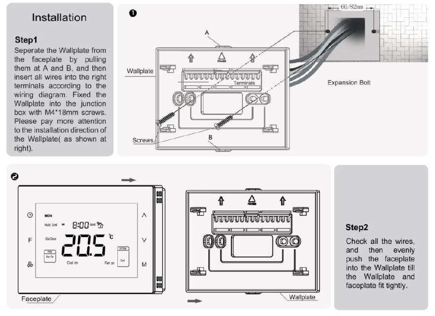
CAUTION: Cut off the power supply at the circuit breaker or fuse before installation to avoid fire, shock, or death!
Wiring diagram
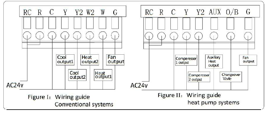
Wiring Terminals
| Terminals | Explanation | Remark |
| RC | Cooling power (two transformers) | Joined with R by jumper (one transformer) |
| R | Heating power (two transformers) | Joined with RC by jumper (one transformer) |
| W (O/B) | Heat output | Changeover valve output (heat pump) |
| Y | Cool output | Compressor output (heat pump) |
| G | Fan output | |
| C | 24VAC common | Connect only when AC power |
| Y2 | Cool output 2 | 2nd stage compressor output (heat pump) |
| W2(AUX) | Heat output 2 | Auxiliary heat output (heat pump) |
Controlling Type
| No. | Type | Terminals | Wiring | Compressor delay |
| 0.0 | 1H/1C (conventional) | R、G、W、Y |
Diagram conventional systems |
none |
| 1.0 | 1H/2C (conventional) | R、G、W、Y、Y2 | none | |
| 2.0 | 2H/2C (conventional) | R、G、W、Y、W2、Y2 | none | |
| 3.0 | 2H/1C (conventional) | R、G、W、Y、W2 | none | |
| 4.0 | 1H/1C (heat pump) | R、G、O/B、Y |
Diagram heat pump systems |
1 min (default) |
| 5.0 | 2H/1C (heat pump) | R、G、O/B、Y、AUX | 1 min (default) | |
| 6.0 | 2H/2C (heat pump) | R、G、O/B、Y、Y2 | 1 min (default) | |
| 7.0 | 3H/2C (heat pump) | R、G、O/B、Y、AUX、Y2 | 1 min (default) |
* Note: Before the operation, pls set the controlling type based on the real situation by referring to the Secret Menu (last page) and following the instruction.
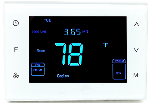
Display & Buttons
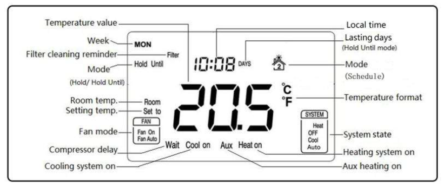
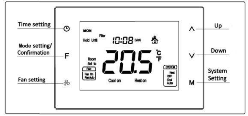
Operation
Temperature format( ℃/ ℉)
In a normal display interface, press ![]() & the F button synchronically for at least 3 sec to switch between ℃ and ℉. (Not available in Hold or Hold Until Mode.)
& the F button synchronically for at least 3 sec to switch between ℃ and ℉. (Not available in Hold or Hold Until Mode.)
Local time setting
Press & hold for 3 sec to enter the interface for the local time setting. Touch to switch among Week, Hour & Minute, and then press
  or
or![]() set the parameters of the flashing item. Press F once, “ ” displayed, and the temperature value flashes for 5 sec. Users can choose to change the value for the temperature setting. If not, press F again to save the time value and return to the normal display. (Local time can not be set in Hold Until mode )
set the parameters of the flashing item. Press F once, “ ” displayed, and the temperature value flashes for 5 sec. Users can choose to change the value for the temperature setting. If not, press F again to save the time value and return to the normal display. (Local time can not be set in Hold Until mode )
Local time setting
Press & hold for 3 sec to enter the interface for the local time setting. Touch to switch among Week, Hour & Minute, and then press or set the parameters of the flashing item. Press F
once, “ ” displayed, and the temperature value flashes for 5 sec. Users can choose to change the value for the temperature setting. If not, press F again to save the time value and return to the normal display.
(Local time can not be set in Hold Until mode )
- OFF: In this state, the Heating, Cooling, and Fan will all be forced close. Displays keep on.
- Auto: In this state, a constant temperature will be kept. The device will activate/ stop the heating/cooling system automatically according to the setting and room temperature.
Conventional system
Heat
- Room temp.≤Setting temp.-1℃, “Heat on” displays and 1st stage heating system is on;
- Room temp.≤Setting temp.-2℃, “Heat on”& “AUX” display and 2nd stage heating system is on; (not available for 1 stage heat system)
- Room temp.≥Setting temp., the heating system stops, and “Heat on” disappears from the screen.
Note: 2nd heat stops and “AUX” disappears when temp. the difference is less than 1 ℃.
Cool
- Room temp.≥ Setting temp.+1 ℃, “Cool on” displays and 1st stage cooling system is on;
- Room temp.≥ Setting temp.+2 ℃, “Cool on” stays and 2nd stage cooling system is on ; (not available for the 1-stage cool system)
- Room temp.≤ Setting temp., the cooling system stops, and “Cool on” disappears from the screen.
Note: 2nd cool stops when temp. the difference is less than 1 ℃.
Heat pump system
Heat (Changeover valve keep closed)
- Room temp.≤Setting temp.-1℃, “Heat on” displays and 1st stage heating system is on;
- Room temp.≤Setting temp.-2℃, “Heat on” stays and 2nd stage heating system is on;
- Room temp.≤Setting temp.-3℃, “Heat on”& “AUX” display and Aux heating system is on;
- Room temp.≥Setting temp., the heating system stops, and “Heat on” disappears from the screen.
Note: Aux heat stops and “AUX” disappears when temp. the difference is less than 2 ℃. 2nd heat stops when temp. the difference is less than 1 ℃.
Cool (Changeover valve keep open)
- Room temp.≥ Setting temp.+1 ℃, “Cool on” displays and 1st stage cooling system is on;
- Room temp.≥ Setting temp.+2 ℃, “Cool on” stays and 2nd stage cooling system is on;
- Room temp.≤ Setting temp., the cooling system stops, and “Cool on” disappears from the screen.
Note: 2nd cool stops when temp. the difference is less than 1 ℃.
Compressor protection
After the operation of the heating/cooling system, there is a 1 min compressor off time to protect the compressor. “Wait” will display on the screen if the next operation is activated within the 1 min period.
Fan mode setting
Press to switch between “Fan on & Fan Auto”.
- Fan on: The fan is always on.
- Fan Auto: The fan runs automatically only when the heating/cooling system is on. (If the system is in the OFF state, the fan will always be off)
Mode setting
Press F to switch between “Schedule, Hold & Hold Until (Holiday)” modes.
- Schedule
Any icon from stands for one time period, and there are 4 periods that can be set in one day. - Press to switch among 7 days → 5+2 days → a whole week: [ MON→TUE→WED→THU →FRI→SAT→SUN→(MON TUE WED THU FRI)→(SAT-SUN)→(MON TUE WED THU FRI SAT SUN) ];
- Press or
 change the flashing hour, minute & temperature value of the chosen day and time period;
 - Press to save your setting and enter into the next period. Users will enter the interface for setting the 1st period of Monday for the first time;
- After 4 periods have been set for one day, press save and enter the schedule set for the following day.
- During setting, press F twice or leave for 15 sec will quit and return to the normal display.
Periods Time Temperature Fan Heating Cooling/ Auto 1 06:00 21.0℃ 25.5℃ Fan Auto 2 08:00 16.5℃ 29.5℃ Fan Auto 3 18:00 21.0℃ 25.5℃ Fan Auto 4 22:00 16.5℃ 28.0℃ Fan Auto
Factory setting Schedules: (Applied in Heat/Cool/Auto system)
Notes: In the process of time periods setting, press the button to modify Fan on or Fan Auto)
Hold
This mode comes after “Schedule” by pressing F. In this mode, the device will keep a constant temperature until the next change.
“Hold” & “ ” display and temperature value flashing. Press or can change the value, and press F to save the setting;
- The press can set the system state;
- The press can set fan mode.
Hold Until (Holiday)
This mode comes after “Hold” by pressing F again. In this mode, the device will follow the setting temperature and lasting days when users are out for a holiday. And then back to following Schedules after the holiday.
- “Hold Until” & “ ” display and temperature value flashing. Press or can change the value, and press F to save the setting. Then days value flashing, users can choose from 1-365 days bypressing or ;
- The press can set the system state;
- The press can set fan mode.
Override temperature setting
During any Schedule period, press or can enter an interface for temperature setting. Press or change the set temperature, and press F to save the change. The changed setting is only valid in the current Schedule period, the device will follow the original schedule in the next period. Filter cleaning reminder “ ” will flash on the screen to remind users of cleaning the furnace filter, and 90 calendar days are the default timing. In Schedule mode, to press for 3 sec, “ ” will disappear from the Override temperature setting During any Schedule period, press or can enter an interface for the temperature setting.
Sensor error “
IF FF” flashes at the temperature display area, it means the temp. the sensor is out of work(short-circuit or broken-circuit), all the outputs will be forced close, and only back to normal
work until the sensor circuit is normal again.
Resorting factory settings
Press ![]() & for 3 sec, “set to” displays and temperature value flashing, then press F to restore factory settings.
& for 3 sec, “set to” displays and temperature value flashing, then press F to restore factory settings.
Installation Set-Up Process-ISU
In Schedule Mode, long press and synchronically can enter into the ISU menu, and the code is 5138. Press or can change the setting, and press can save and switch to the following item.
Table 1
| Item | Explain | Range | Default | Remark |
| 0 | Controlling Type | 0.0-7.0 | 0.0 | See table “Controlling
Type” |
| 1 | (1H/1C)Differential | 0.5℃/1℃/1.5℃/2℃ | 1.0℃ | |
| 2 | Temperature calibration | -10℃~10℃ | 0.0℃ | |
| 3 | Temperature setting upper limit | 0-99.5℃ | 37.0℃ | Upper limit value > lower limit value |
| 4 | Temperature setting lower limit | 0-99.5℃ | 5.0℃ | |
| 5 | Filter change reminder | 1 /2 /30 /60 /90 /120 days | 090 days | |
| 6 | Clock format | 12 /24 hours | 24.0 | |
| 7 | Compressor protection delay | 0~10min | 1.0min | |
| 8 | Backlight setting | ON/OF | OF | ON back-lit always on
OF back-lit half bright when no operation |
| 9 | Temperature format | ℃/℉ | ℃ | |
| Restore factory setting | OF/ON | OF | ON for restoring |
Hotowell International Co., Limited Phone:+86-592-3327332 E-mail:[email protected] Add.:Building 7, Guanyinshan International Business Center, Xiamen 361000, China
REFERENCE:
DOWNLOAD MANUALS:
hotowell HTW-81-FN7 Thermostat Product Specification Guide
![]()
Leave a Reply