
HITACHI PC-ART REMOTE CONTROLLER Thermostat

Read and understand this manual before using this air conditioner. Keep this manual for future reference.
REMOTE CONTROLLER OPERATION
OPTIONAL LIQUID CRYSTAL REMOTE CONTROL PC-ART

- Fan speed indicator
Indicates the ventilation speed selected:- (High / Medium / Low)
- Indicator of Total ventilator
- Indicates if the total heat exchanger has been selected.
- A/C-only air conditioning
- VENTI only ventilation
- A/C + VENTI if both are selected
- Operation Mode Indicator
Indicates the operation mode selected: Fan/Cool/Heat/Dry/Auto (Cool/Heat) - Run indicator (Red lamp)
- RUN/STOP switch
- MODE (Operation Mode Selection) switch% FAN SPEED
- (Fan Speed Selection) switch & Up & down
- panel operation switch
- VENTI (ventilator operation) switch
- LOUVER (deßector panel) switch
- SELECT (Day/Schedule) switches
Increase and decreases the Day/Schedule for timer operation. - ON/OFF TIMER switch
Used to activate or deactivate the timer operation. - OK switch
- RESET (Filter Reset Switch)
After cleaning the air Þ later, press the “RESET” button. The FILTER indication will disappear and the next Þ later cleaning time is reset. It also stops the run procedure. - TEMP (temperature setting) switches
- RUN (test run indication)
Check (check indication) These tests appear when TEST RUN or CHECK are being performed. - ABNML (alarm) indicator
- SET TEMP (set temperature) indicator
- (setting schedule number)
- Mon Tue … Sun indicator (day of the week indicator).
Indicates that the central station or CSNet control is operating. - Swing louver indicator DEFROST indicator
- SERVICE mode indicator.
Indicates the change to special operations - Time indicator.
- Time indicator. (Indicates the programmed time).

NOTE
- If the LOW fan speed is selected and the outdoor temperature is higher than 21°C, the compressor is subjected to an excessive load when operating in heating mode.
- Therefore, the fan speed should be set to HIGH or MEDIUM to avoid activating the safety devices.
- When the system is restarted after a shutdown of more than approximately 3 months, the system should be checked by your service provider.
- Turn off the main switch when the system is to be inoperative for a long period of time. Otherwise, the system consumes electricity as the oil heater remains active even though the compressor is stopped.
OPERATION PROCEDURE FOR COOLING, HEATING, DRY, AND FAN OPERATIONS
| � Before operation:
– Turn on the electrical power supply to the system approximately 12 hours before start-up after a long shutdown. Do not start the system immediately after connecting the power supply, because the compressor may be damaged if it is not sufficiently heated. – Make sure the outdoor unit is not covered with ice or snow. If it is, remove the ice or snow with warm water (no hotter than 50°C). – If the water temperature is over 50°C, the plastic parts may be damaged. |
 |
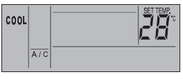
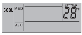
| 1. Turn on the power supply.
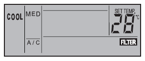
Three vertical lines will appear on the liquid crystal display, with the indication A/C or VENTI. 2. Press the MODE switch. By repeatedly pressing the MODE switch, the indication changes from COOL, through HEAT, DRY to FAN, in that order (in the case of cooling-only models, COOL, DRY and FAN). (The figure shows when the “COOL” mode setting is selected). |
 |
| 3. Press the RUN/STOP switch.
The RUN indicator (red) lights up. The system starts automatically.
NOTE: Setting temperature, fan speed and air louver direction. The setting is memorized after the irst time and does not require resetting every day. When the setting needs to be changed, refer to the section “Setting the Temperature, Fan Speed and Air Louver Direction”. |
 |
| 4. Switch OFF (STOP)
Press the RUN/STOP switch again. The RUN indicator (red) is OFF. The system is automatically stopped.
NOTE: The fan may continue operating for approximately 2 minutes after the heating operation is stopped. |
 |
SETTING THE TEMPERATURE, FAN SPEED, AND AIR LOUVER DIRECTION
| � DO NOT touch the OK switch.
– The OK switch is used only for servicing. – If the OK switch is pressed by mistake and the mode is changed from operation to check mode, press the OK switch again for approximately 3 seconds, wait 10 seconds and then press again. – The mode will change back to normal. |
 |
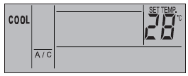
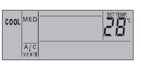
| � Setting the temperature
– Set the temperature by pressing the TEMP (0) or 19 switch. – The temperature increases 1°C when the (0) switch is pressed (max 30°C). – The temperature decreases 1°C when the 19 switch is pressed (min. 19°C for COOL, DRY and FAN modes; min. 17°C for HEAT mode). (The figure shows the temperature set to 28°C). |
 |
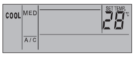
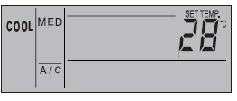
| � Setting Fan Speed
– Press the FAN SPEED switch. – When the FAN SPEED switch is pressed repeatedly, the indication changes from HIGH to MEDIUM to LOW, in that order. – For normal operation, set the fan speed to HIGH. (The figure shows the fan speed set to MED.) NOTE: In the DRY mode, the fan speed automatically changes to LOW, and cannot be altered (however, the indication shows the current setting). |
 |
| � Setting the swing louver direction
Press the SWING LOUVER switch: the louver begins to swing. Pressing the switch again fixes the position of the swing louver. Pressing the switch repeatedly stops and swings the louver successively. � Fixed position The indication shows the air flow direction. � Automatic swing position The indications move continuously corresponding to the louver swing.
NOTE: In the heating operation, the louver angle changes automatically. |
|
OPERATION PROCEDURE FOR VENTILATION
| This function is available only when the total heat exchanger is connected.
If the procedures below are performed when the total heat exchanger is not connected, the NO FUNCTION indication blinks for 5 seconds. |
|
| � Ventilation
Press the VENTI switch By repeatedly pressing the VENTI switch, the indication changes from A/C through VENTI and A/C+VENTI, in that order. (The figure shows the A/C + VENTI setting). NOTE: Contact your distributor or HITACHI dealer for detailed information. If the mode is changed to VENTI during individual operation of the air conditioner, the air conditioner will stop. If the mode is changed to A/C during individual operation of the total heat exchanger, the total heat exchanger will stop. |
 |
OPERATION PROCEDURE FOR AUTOMATIC COOLING/HEATING OPERATION
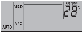
The automatic cooling/heating operation must be set using the optional function. Contact your distributor or HITACHI dealer for more detailed information. This function enables the operation mode (cooling or heating) to be changed automatically according to the temperature difference between the set temperature and the suction air temperature. If the suction air temperature exceeds the set temperature by 3°, the operation changes to COOL mode. If it is 3°C lower than the set temperature, the operation changes to HEAT mode.
NOTE:
If the heating operation is set at the LOW fan speed, the protective devices will often cause the system to stop. In this case, set the fan speed to HIGH or MED. If the outside temperature is over approximately 21°C, the heating operation is not available. The temperature difference between the cooling and heating operations is quite considerable when this function is used. This function cannot, therefore, be used for air conditioning in a room where accurate control of temperature and humidity is required.
PROCEDURE FOR SETTING THE SWING LOUVER
| Setting the swing louver | 1. When the SWING LOUVER switch is pressed, the swing louver starts its horizontal to vertical position. When the “…“ symbol is moving, this operation. The range of the angle of the swing is approximately 70° from indicating the continuous operation of the louver.
2. When the swinging operation of the louver is not required, press the SWING direction of the
3. The discharge air angle is fixed at 20° for the RCI series and 40° for RCD series during the start-up of the heating and defrosting operation when the thermostat is on. When the outlet air. temperature exceeds approximately 30 C, the louvers start to swing. |

|
| Fixing the louver | 1. For COOL and DRY modes, the discharge air angle can be changed to 5 different positions. For the heating operation, it can be changed to 7 positions.
2. To fix the louver position, first press the SWING LOUVER switch to start the louver swinging, and then press again when the louver reaches the required position. 3. The discharge air angle is fixed at 20° for the RCI series and 40° for the RCD series during the start-up of the heating and defrosting operation when the thermostat is on. When the outlet air temperature exceeds approximately 30 °C, the louvers start to swing.
When the louvers are fixed at an angle of 55° for RCI, 65° for RCD or 70° for both during the heating operation and the operation mode is changed to cooling, the louvers will be automatically fixed at an angle of 45° for RCI or 60° for RCD.
NOTE: There is a time lag between the actual angle of the louver and the indication on the liquid crystal display. When the SWING LOUVER switch is pressed, the louver will not stop immediately. The louver will move one extra swing. If the louvers are moved when cleaning or for any other reason, select the auto-setting mode to move the four louvers to the same position. |
 . LOUVER switch again. The louver stops at the angle indicated by the
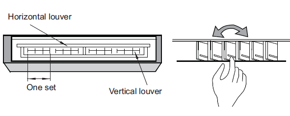
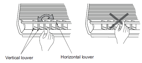
| Do not turn the air louver by hand. The louver mechanism may be damaged if moved (in all units). | |
| � Wall-mounted type (RPK):
Adjust the vertical louvers by hand to discharge air in the required direction. Do not swing blade 1 to the left and blade 2 to the right of the vertical louvering. � Automatic setting of the louver: When the unit is not in operation, two air louvers stop automatically in the closed position. |
|
| � Ceiling-mounted type (RPC):
The vertical louver consists of four sets of louvers. Adjust the vertical louvers by hand to discharge air in the required direction. NOTE: The models which do not have a swing louver will not show the above indications on the remote control. In this case, the louver must be adjusted manually. |
|
TIMER OPERATION PROCEDURE
Setting the current day and time
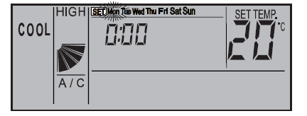
| 1. Hold down the SELECT (v) DAY switch for more than 3 seconds to change to current day setting mode. SET is indicated and the day blinks. All the days except the current day are indicated. |
|
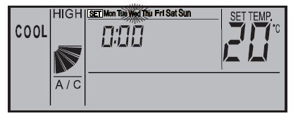
| 2. Hold down the SELECT (v) DAY switch until the current day blinks, then press OK. The date is indicated, and the time blinks. |
|
| 3. Press the SELECT (L’v) DAY / SCHEDULE switches to adjust the “hour” setting, and then press again. “Hour” is indicated and “minutes” blinks. |
|
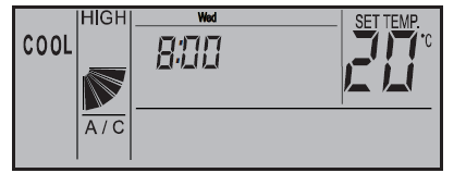
| 4. Press the SELECT (L’v) DAY / SCHEDULE switches to adjust the “minutes” setting, and then press again.
The current time setting mode ends and returns to normal mode. “Minutes” is indicated and the SET indication goes out. The “seconds” start from zero. |
|

Setting the timer (programming)
|
SET |
|
||
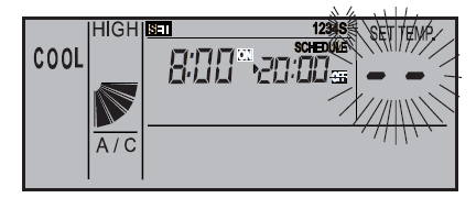
| 1. Press the TIMER switch. SET and SCHEDULE are indicated. Schedule number “1” blinks and other numbers | : | 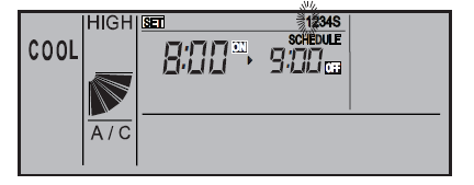 |
|
| 2. When the SCHEDULE switch (L’) is pressed, the schedule number moves
[1] – [2] – [3] – [4] – [S] – [1]-…. – Select [S] to set the ON/OFF time and temperature shifts. – By pressing the TIMER switch, the SET and SCHEDULE indicators go out and the mode changes back to normal. |
SET |
: |
|
|
SET |
1 |
||
| 3. When the OK switch is pressed, the selected schedule number is indicated. The other schedule number | : | 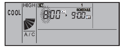 |
|
| indicators go out, and the ON time “hour” indicator for the number selected blinks. | |||
| 4. Press the SELECT (L’v) DAY / SCHEDULE switches to adjust the “hour” setting, and then press again. |
SET |
 |
|
| “Hour” is indicated and “minutes” blinks. | |||
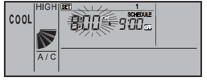
| 5. Press the SELECT (L’v) DAY / SCHEDULE switches to adjust the “minutes” setting, and then press again. |
SET |
: |  |
| “Minutes” is indicated and the OFF time “hour” setting blinks. | |||
|
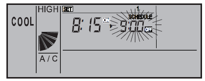
6. Set the OFF time the same way as the ON time. After setting the “minutes”, the OFF time is indicated. If the |
SET |
 |
|
| schedule number [1][2][3][4] is selected, the indication changes to set the schedule number shown in 2. If [S] is | 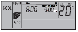 |
||
| selected, see the section on setting temperature shifts for details. |
| 7. By pressing the (L’v) DAY / SCHEDULE switches, the SET and SCHEDULE indicators go out and the mode returns to normal. |
|

Defining the schedule to be applied
| 1. Hold down the (L’v) DAY/SCHEDULE switches for more than 3 seconds and the SET indicator appears.
All the days and schedule numbers are indicated. |
|
|
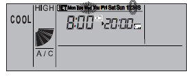
| 2. Press the (L’v) DAY/SCHEDULE switches until the day you wish to set blinks. When pressed, the day
blinks [Mon] – [Tue] -… – [Sun]- [Mon~Sun] – [Mon~Fri] – [Sat, Sun] – [Mon]… If several days are blinking, the same setting will be applied to all the days. |
||
| 3. Press the (L’) DAY switch until the schedule number you wish to set blinks. |
|
|
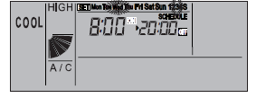
| 4. Press the (v) SCHEDULE, and the SCHEDULE indication appears. Then the schedule number indicated |
|
|
| in step 3 is applied to the days set in step 2. Press the OK switch to activate or deactivate the schedule. If the | ||
| schedule is activated, the word SCHEDULE is lit up. | ||
|
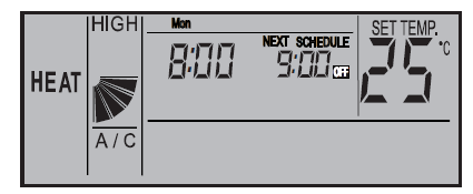
5. Press the TIMER switch and the mode returns to normal. |
Mon : |
|
Canceling the timer
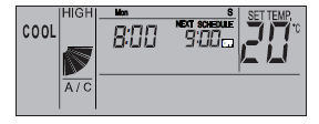
| In the normal mode, hold down the (L’v) DAY / SCHEDULE switches for more than 3 seconds. The NEXT SCHEDULE indicator blinks. (Cancellation of all the timer) |
|
| While the timer is in cancellation mode, hold down the (L’v) DAY / SCHEDULE switches for more than 3 seconds. NEXT SCHEDULE is indicated. (Timer activation) |
|
Setting the temperature shifts (energy saving mode)
|
SET |
1234S |
||
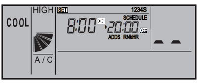
| 1. Set the ON/OFF operation as in steps 1 and 2 of the “Setting the timer” section, and then select “S” as the | : | 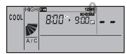 |
|
| schedule number. | |||
|
SET |
1234S |
||
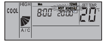
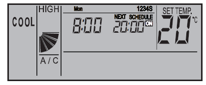
| : | ON SCHEDULE
|
||
| 2. Set the ON/OFF operation in steps 4,5 and 6 of the “Setting the timer” section, and set the ON/OFF time. The |
|
||
| temperature setting is then indicated. | |||
| 3. Select the temperature shift with the (0)19 switches. “3” or “5” can be selected. If the reset switch is pressed at |
SET |
: |
|
| this time, the temperature shift is not set and the indication “- -“ appears. When the TIMER switch is pressed, | |||
| the temperature is indicated and the mode changes to schedule number selection. | |||
|
4. When the TIMER switch is pressed, the SET and SCHEDULE indicators go out and the mode returns to normal. |
Mon : |
S NEXT SCHEDULE : OFF |

NOTE
- When this operation is performed, the temperature shift indicator changes.
- When this operation is performed, the temperature setting of the CSNET NET WEB or PSC-A64S has a normal range, while the remote control setting may be changed to a new range.
- The increase or decrease in the temperature setting during the scheduled time (±3 ºC or ±5 ºC) varies according to the operation mode. If the system is operating in FAN, COOL or DRY mode, the temperature variation is + . If the system is operating in HEAT, mode, the temperature variation is
Automatic operation with heating (anti-freeze protection)
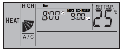
| 1. In normal mode, hold down the switch for more than 3 seconds to change the operation mode. The automatic heating setting is activated and the ON indicator appears to the right of the current time. The ON indication blinks during the automatic heating operation. |
Mon : |
ON |
|
| – Cancellation
While the system is operating in the automatic heating mode, hold down the MODE switch for more than 3 seconds to change back to normal mode.The automatic heating setting is deactivated, and the ON indication to the right of the current time goes out. |
Mon : |
|
|
NOTE
If the temperature in the room is lower than a predeÞ ned value1*, the heating will start up automatically. When the room temperature reaches the set temperature, the operation stops. The temperatures 5,10, or 15ºC can be selected using an optional setting.
Operation locking method
| To prevent incorrect use of the switches, the switch operation * can be locked. | ||
|
Mon |
||
| 1. In normal mode, hold down the SELECT (0)19 switch for more than 3 seconds. The operation lock is activated | : | 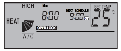 |
| and the OPER.LOCK indication appears. If a switch is pressed while it is locked, the indication OPER. LOCK |
OPER.LOCK |
|
| blinks. | ||
| Cancellation
While the locking operation is activated, hold down the (0)19 switch and SELECT simultaneously for more than 3 seconds to return to normal mode. The locking operation will be canceled and the OPER. LOCK indication goes out. |
Mon : |
|

NOTE
The switch to be locked can be selected from “operation mode change”, “temperature setting”, “airß ow” and “autoloader” by an optional setting (F8~Fb) of up to 4 items. The setting can be changed from CSNET or the sub-remote controller.
INDICATIONS UNDER NORMAL CONDITIONS
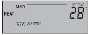
| � Thermo-controller
When the thermo-controller is operated, the fan speed changes to LOW, and the indication remains unchanged. (Only in heating mode) |
 |
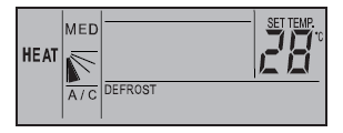
| � Defrosting
When the system is operating in defrost mode, the DEFROST indication is shown. The indoor fan slows down or stops (depending on the setting selected). The louver is fixed horizontally at 35°. However, the LCD indication is still activated. (The figure shows the DEFROST setting). |
 |
|
When the unit stops during the defrosting operation, the RUN indicator (red) goes out. However, the operation continues to show the DEFROST indication, and the unit starts up once the defrost operation is finished. |
 |
| � Filter
Clogged filter: The “FILTER” indication appears when the filter is clogged with dust, etc. Clean the filter: Press the RESET switch after cleaning the filter. The “FILTER” indication goes out. |
 |
INDICATIONS UNDER ABNORMAL CONDITIONS
Dysfunction

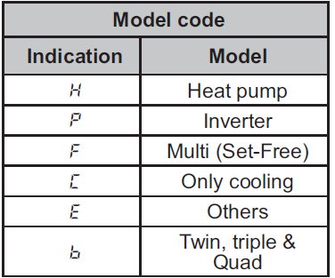
The RUN indicator (red) blinks. The ALARM indicator appears on the liquid crystal display. The indoor unit number, the alarm code and the model code are indicated on the liquid crystal display. If several indoor units are connected, the above items are indicated one by one for each of them. Make a note of the indications and contact your HITACHI service provider.
Power failure
All the indications disappear. If the unit stops because of a power failure, it will not restart even when the power returns. Perform the start-up operations again. If the power failure lasts less than 2 seconds, the unit will automatically start up again.
Electrical noise
The indications may all be OFF and the unit stopped. This is because the microcomputer has been activated in order to protect the unit from electrical noise.
NOTE:
If the wireless remote control switch is used for the wall-mounted indoor unit, remove the connectors (CN25) connected to the indoor PCB. If they are not removed, the unit will not operate. The memorized data can not be erased unless the remote control switch is initialized.
CHECKING PROCEDURE
Turn ON the power supply for all the indoor units. Set the “TEST RUN” mode by pressing the “MODE” and “OK” switch simultaneously for more than 3 seconds.
ATTENTION
In the case of the control by using two Remote controllers (Main & Sub), the test running shall be operated by the main controller.
NOTE
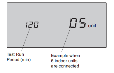
The completion of the automatic address setting requires 3 to 5 minutes after turning ON the power supply. The total number of the connected units is indicated on the liquid crystal display
- In case the indicated number is not correct, some abnormalities exist, incorrect wiring, electric noise, etc.
- Turn OFF the power supply and correct the wiring after checking the following points; (Do not repeat turning ON and OFF within 10 seconds.)
- The power Supply for Indoor Unit is Not Turned ON or has Incorrect Wiring.
- Incorrect Connection of Connecting Cable between Indoor Units or Incorrect Connection of Controller Cable.
- Incorrect Setting of Rotary Switch (The setting is overlapped.) on the Indoor Units PCB.
- Check to ensure that the “Test Run” mode is not set.
- Set the required Test Run period by pressing E and F (Min. 10 minutes to Max. 600 minutes).
Canceling “Test Run” Mode.
When the unit is not operating, press the RESET switch. When the unit is operating, press the RUN/STOP switch.
CAUTION
When “00” is indicated, the auto address function may be performing. Cancel the “Test Run” mode and set it again.
OPTIONAL SETTING AND INPUT/OUTPUT SETTING OF INDOOR UNIT

INITIALIZATION OF OPTIONAL SETTINGS AND INPUT/OUTPUT
The procedure for initialization of optional settings and input/output settings is as follows.

TABLE A OPTIONAL SETTING ITEMS
| No. | Items | Optional Function | Individual Setting | Setting Condition | Contents |
|
1 |
b1 |
Removal of Heating Temperature Compensation |
|
00
01 02 |
Standard (Set Temp.
+4ºC) Removal (Set Temp.) Set Temp. +2ºC (*1) |
|
2 |
b2 |
Circulator Function at Heating Thermo- OFF | 00
01 |
Not Available Available | |
|
3 |
b3 |
3 Minutes OFF Guard Compressor | 00
01 |
Not Available Available | |
|
4 |
b4 |
Period for Filter Sign |
|
00
01 02 03 04 |
Standard 100 hours
1,200 hours 2,500 hours No Indication |
| 5 | b5 | Fixing of Operation Mode | × | 00
01 |
Not Available Available |
| 6 | b6 | Fixing of Setting Temperature | × | 00
01 |
Not Available Available |
| 7 | b7 | Fixing Cooling Operation | × | 00
01 |
Not Available Available |
| 8 | b8 | Automatic COOL/ HEAT Operation | × | 00
01 |
Not Available Available |
| 9 | b9 | Fixing Fan Speed | × | 00
01 |
Not Available Available |
| 10 | bA | Not Prepared | × | “- -” Fixed | Not Used |
|
11 |
bb |
Cooling Temperature Compensation |
00
01 02 |
Standard (No Compensation) Set Temp. –1ºC Set Temp. –2ºC | |
|
12 |
bC |
Not Prepared |
– | 00
01 |
Not Used
(Use as 00 conditions) |
| 13 | bd | Not Prepared | – | 00
01 |
Not Used
(Use as 00 conditions) |
| 14 | bE | Not Prepared | – | 00
01 |
Not Used
(Use as 00 conditions) |
|
15 |
C1 |
Not Prepared |
– | 00
01 |
Not Used
(Use as 00 conditions) |
| 16 | C2 | Not Prepared | – | “- -” Fixed | Not Used |
| 17 | C3 | Not Prepared | 00
01 |
Not Used
(Use as 00 conditions) |
|
| 18 | C4 | Not Prepared | 00
01 |
Not Used
(Use as 00 conditions) |
|
|
19 |
C5 |
Increasing Fan Speed | 00
01 02 |
Not Available Hi Speed 1 (*2) Hi Speed 2 (*2) | |
| 20 | C6 | Increasing Fan Speed | 00
01 |
Not Available Available | |
| 21 | C7 | Canceling 3 Minutes Compressor Guard. | 00
01 |
Available Not Available | |
| 00 | Not Available | ||||
| 01 | Control by Indoor | ||||
| Suction Thermistor | |||||
|
22 |
C8 |
Thermistor of Remote Control Switch | 02 | Control by Thermistor of Remote Control Switch Control by
Average Value of Indoor |
|
| Suction Thermistor and | |||||
| Thermistor of Remote | |||||
| Control Switch | |||||
| 23 | C9 | Not Prepared | – | “- -” Fixed | Not Used |
| 24 | CA | Not Prepared | – | “- -” Fixed | Not Used |
| 00 | Forced Stoppage Input: | ||||
| 25 | Cb | Selection of Forced
Stoppage Logic |
× |
01 |
A Contact
Forced Stoppage Input: |
| B Contact | |||||
| 26 | CC | Not Prepared | × | 00
01 |
Not Used
(Use as 00 conditions) |
| 27 | Cd | Not Prepared | 00
01 |
Not Used
(Use as 00 conditions) |
|
| 28 | CE | Not Prepared | – | 00
01 |
Not Used
(Use as 00 conditions) |
|
29 |
CF |
Change of Louver Swing Angle |
|
00
01 02 |
Standard (7 Steps)
Draft Prevention (5 Steps) High Ceiling (5 Steps) (*3) |
| 30 | d1 | Power Supply ON/OFF 1 | 00
01 |
Not Available Available | |
| 31 | d2 | Not Prepared | – | “- -” Fixed | Not Used |
| 32 | d3 | Power Supply ON/OFF 2 | 00
01 |
Not Available Available | |
|
33 |
d4 |
Prevention for Cooling Discharge Air Temp. Decrease | 00
01 |
Not Available Available | |
|
34 |
d5 |
Prevention for Heating Discharge Air Temp. Decrease | 00
01 |
Not Available Available | |
| 35 | d6 | Room Temp. Control for Energy Saving | 00
01 |
Not Available Available |
| No. | Items | Optional Function | Individual Setting | Setting Condition | Contents |
| 36 | d7 | Not Prepared | 00~07 | Not Used
(Use as 00 conditions) |
|
| KPI: | |||||
| 00
01 |
Automatic Ventilation Ventilation by Total
Heat Exchanger |
||||
| 37 | E1 | Ventilation Mode | 02 | Bypass Ventilation
(No Total Heat |
|
| Exchanging) | |||||
| Econofresh: | |||||
| 00 | Not available | ||||
| 01/02 | All fresh mode | ||||
| 38 | E2 | Increasing Supply Air Volume | 00
01 |
Not Available Available | |
| 39 | E3 | Not Prepared | 00
01 |
Not Used
(Use as 00 conditions) |
|
| KPI: | |||||
| 00 | Standard | ||||
|
40 |
E4 |
Precooling / Preheating Period |
01
02 |
30 min.
60 min. |
|
| Econofresh: Standard CO Sensor
2 |
|||||
| 00 | |||||
| 01/02 | |||||
| 41 | E5 | Not Prepared | 00
01 |
Not Used
(Use as 00 conditions) |
|
|
42 |
E6 |
Indoor Fan Operation Time After Cooling Operation Stoppage | 00
01 02 |
Not Available 60 min.
120 min. |
|
| 43 | E7 | Not Prepared | – | 00
01 |
Not Used
(Use as 00 conditions) |
|
44 |
E8 |
Fan Operation Control at Heating Thermo-OFF | 00
01 |
Not Available Available | |
| 45 | E9 | Not Prepared | – | 00
01 |
Not Used
(Use as 00 conditions) |
|
46 |
EA |
Not Prepared |
00
01 02 |
Not Used
(Use as 00 conditions) |
|
| Fan Operation | 00 | Not Available | |||
| 47 | Eb | Control at Cooling | 01 | LOW | |
| Thermo-OFF | 02 | SLOW | |||
| 48 | EC | Forced Thermo-ON Stoppage at Cooling | 00
01 |
Not Available Available | |
| 49 | Ed | Not Prepared | 00
01 |
Not Used
(Use as 00 conditions) |
|
| 50 | EE | Automatic Fan Speed Control | 00
01 |
Not Available Available | |
| 51 | F1 | Not Prepared | – | 00~0B | Not used |
| 52 | F2 | Remote Control Main-Sub Setting | × | 00
01 |
Main Sub |
| 53 | F3 | Not prepared | – | 00~01 | Not used |
| 54 | F4 | Not prepared | – | 00~03 | Not used |
| 55 | F5 | Not prepared | – | 19~30 | Not used |
| 56 | F6 | Not prepared | – | 17~30 | Not used |
| 57 | F7 | Not prepared | – | 00~01 | Not used |
|
58 |
F8 |
Lock Function for Operation Mode Selection | × | 00
01 |
Not Available Available (Factory-Setting) |
|
59 |
F9 |
Lock Function for Temperature Setting | × | 00
01 |
Not Available Available (Factory-Setting) |
|
60 |
FA |
Lock Function for Fan Speed Selection | × | 00
01 |
Not Available Available (Factory-Setting) |
|
61 |
Fb |
Lock Function for Swing Louver Operation | × | 00
01 |
Not Available Available (Factory-Setting) |
|
62 |
FC |
Cooling Lower Limit for Setting Temperature (*4) |
× |
00
01 02 • • 09 10 |
Standard
Lower Limit +1ºC Lower Limit +2ºC • • Lower Limit +9ºC Lower Limit +10ºC |
|
63 |
Fd |
Heating Upper Limit for Setting Temperature (*5) |
× |
00
01 02 • • 09 10 |
Standard
Upper Limit –1ºC Upper Limit –2ºC • • Upper Limit –9ºC Upper Limit –10ºC |
|
64 |
FE |
Not Prepared |
– | 00
01 02 |
Not Used (Use as 00 conditions) |
|
65 |
FF |
Lock Function for Timer | × | 00
01 |
Not Available Available (Factory-
setting) |
NOTES:
- The “02” setting may not be available according to the type of indoor unit.
- In case of RPI models, 00: Increasing fan speed 1 (standard), 01: Increasing fan speed 2 (high static pressure), 02: Standard (low static pressure)
- 00: Standard (7-step operation), 01: Draft Prevention (lower 2 steps cutoff), 02: High ceiling (upper 2 steps cut off)
- Applicable to fan, cooling, and dry operation modes.
- Applicable to the heating operation mode.
- After at least 3 minutes from the power ON, change the optional setting.
- When changing the “CF” setting (change of louver swing range), restore the power supply or allow the louver to make one complete swing fully in the auto swing mode to apply the optional setting.
- The optional settings are different according to the indoor and outdoor unit models. Check to ensure that the unit has the optional setting or not.
- Record the setting conditions for each optional setting in the “Setting” column of the table.
TABLE B INPUT AND OUTPUT NUMBER
DISPLAY AND CONNECTORS
| Input number display |
Port |
Factory Setting |
Setting |
||
| Input / Output |
Indication |
Setting Item |
Indiicaton |
||
|
Input1 |
CN3 1-2 | Remote ON/ OFF 1 (level) |
03 |
||
|
Input2 |
|
CN3 2-3 |
Forbidding Remote Control after Manual Stoppage |
06 |
|
|
Output1 |
CN7 1-2 |
Operation |
01 |
||
|
Output2 |
CN7 1-3 |
Alarm |
02 |
||
|
Output3 |
3 | CN8 1-2 | Thermo-ON for Heating |
06 |
|
TABLE C INPUT AND OUTPUT SETTINGS
AND DISPLAY CODES
| Indication | Input | Output |
| 00 | Not set | Not set |
| 01 | Room Thermostat (for Cooling) | Operation |
| 02 | Room Thermostat (for Heating) | Alarm |
| 03 | Remote ON/OFF 1 (level) | Cooling |
| 04 | Remote ON/OFF 2 (Operation) | Thermo-ON for Cooling |
| 05 | Remote ON/OFF 2 (Stoppage) | Heating |
| 06 | Forbidding Remote Control after Manual Stoppage | Thermo-ON for Heating |
| 07 | Remote Cooling / Heating Change | Total Heat Exchanger |
NOTES
After at least 3 minutes from the power ON, change the optional setting. Record the setting conditions for each input and output in the “Setting” column of the table.
CHANGING INDOOR UNIT ADDRESS FROM REMOTE CONTROL SWITCH
The address (unit number) of the indoor unit can be changed by using the remote control switch (PC-ART).
NOTES
- In the case of operating with two remote control switches (master and slave), the address of the indoor units cannot be changed or checked.
- The address may not be able to be changed depending on the type of indoor unit.
- Do not operate the central controller when in the address check mode or address change mode.
- Check the Indoor Unit for which the address to be changed. The address of the Indoor Unit to be Changed is not known (check) . . . Proceed to (2) Address Check Mode.
- The address of the Indoor Unit to be Changed is known . . . Proceed to (3) Address Change Mode.
- Initialize address set with the automatic address function or initialize address that has been changed with the address change mode. . . Proceed to (4)
- Address Initialization Mode.
Address Check Mode
This function is for two or more indoor units connected to the remote control switch. The indoor unit address can be checked by the indoor unit individual operation by selecting the indoor address.

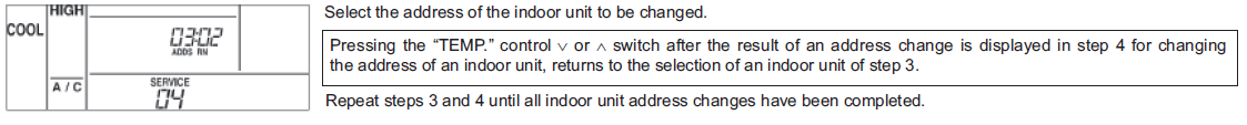
Address Change Mode
Change the address (unit number) of the indoor unit.
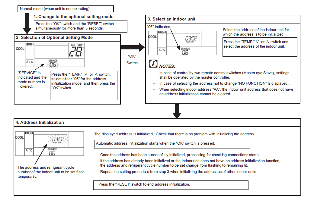
Address Initialization
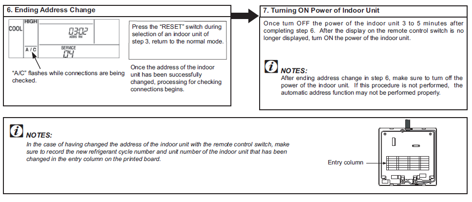
This is used to initialize an address that has been changed in the address change mode or to initialize an indoor unit address that has been set with the automatic address function. When set this function, the address of the indoor unit is returned to the dip switch setting. (ReconÞ guration automatic address setting if the dip switch setting to the automatic address setting.)
 Reference:
Download Manual:
HITACHI PC-ART REMOTE CONTROLLER Thermostat Installational Manual
![]()
HITACHI PC-ART REMOTE CONTROLLER Thermostat Installational Manual
Leave a Reply