
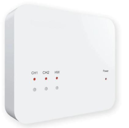
Heatmisser RF-Switch Wireless Thermostat
Installing the RF-Switch
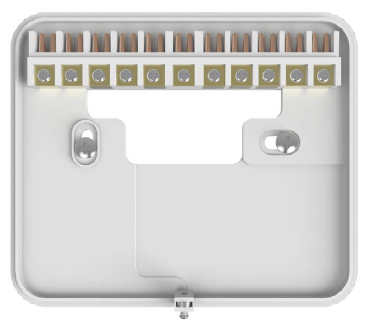
- Using a small screwdriver, slightly loosen the screw located at the base of the RF-Switch. You can then carefully separate the front panel from the back plate.
- Position the RF-Switch back plate on the wall, fixing into place using the screws provided.
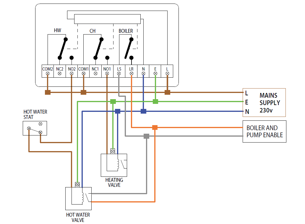
- Terminate the cables to the RF-Switch as shown in the wiring diagram (section 6).
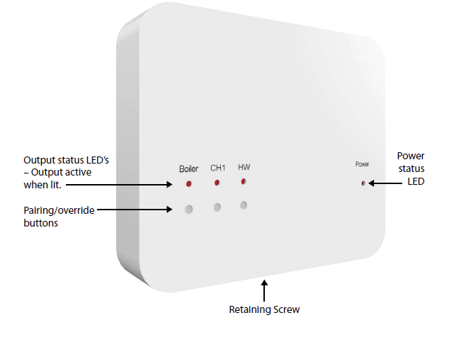
- Mount the front panel onto the back plate, tighten the retaining screw on the base.
- Switch on the power supply, the power LED will illuminate
Overriding the RF-Switch outputs
- To override an output on the RF-Switch, simply press the override button once, the output & LED will then be activated.
- To override the output off, press the button once.
Pairing the RF-Switch to the UH8-RF
- On the RF-Switch, press and hold the Boiler pairing button for 5 seconds.
- The Boiler status LED will switch on.
- Press and release the pairing button on the UH8-RF.
- When the RF-Switch detects the pairing signal from the UH8-RF, the Boiler LED will switch off.
- To pair your wireless thermostat to the RF-Switch, please refer to your wireless thermostat instruction manual
Factory Resetting the RF-Switch
- To reset an output of the RF-Switch, follow these steps;
- Press and hold both the Boiler & HW pairing buttons for 5 seconds.
- The LED’s on the RF-Switch will now flash.
- Press and release the button of the channel to reset.
- For example pressing the CH1 button, will erase all devices paired to The CH1 channel.
- Once the LED’s have stopped flashing the reset procedure is complete.
RF-Switch Wiring Diagram
Reference
Download manual:
Heatmisser RF-Switch Wireless Thermostat INSTALLATION GUIDE
Leave a Reply