
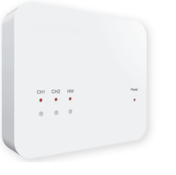
Heatmiser RF Switch v2 Wireless Receiver THERMOSTAT
Installing the RF-Switch V2
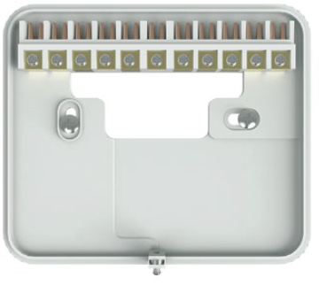
- Using a small screwdriver, slightly loosen the screw located at the base of the RF-Switch. You can then carefully separate the front panel from the back plate.
- Position the RF-Switch back plate on the wall, fixing into place using the screws provided.
- Terminate the cables to the RF-Switch as shown in the wiring diagram (section 6).
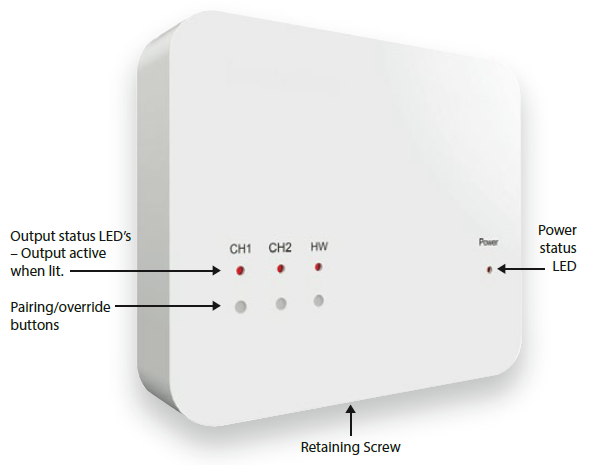
- Mount the front panel onto the back plate, tighten the retaining screw on the base.
- Switch on the power supply, the power LED will illuminate.
Overriding the outputs
- To override an output on the RF-Switch V2, simply press the override button once, the output & LED will then be activated.
- To override the output of, press the button once.
Pairing the RF-Switch to the UH8-RF/UH8-RF V2
- On the RF-Switch, press and hold the CH1 pairing button for 5 seconds.
- The CH1 status LED will start to flash.
- Press and release the pairing button on the UH8-RF.
- When the RF-Switch detects the pairing signal from the UH8-RF, the CH1 LED will stop flashing.
- To pair your wireless thermostat to the RF-Switch, please refer to your wireless thermostat instruction manual.
- When pairing a thermostat in combined heating/hotwater mode, you do not need to pair to the HW channel. This is done automatically when the stat is paired to either CH1 or CH2
Channel Reset
- To reset an output of the RF-Switch;
- Press and hold the pairing/override button of the desired channel for 15 seconds.
- During the button press you will see the LED flash steadily followed by a rapid flash.
- Once the LED has stopped blinking, the reset procedure is complete and will erase all devices paired to that channel
RF-Switch Wiring Diagram (S Plan)

Heatmiser
Want More Information?
Call our support team on: +44 (0)1254 669090 Or view technical specifications directly on our website: www.heatmiser.com
- Heatmiser UK Ltd
- Units 1-5 Hurstwood Court, Mercer Way
- Shadsworth Business Park, Blackburn,
- Lancashire, BB1 2QU, United Kingdom
- Twitter: @heatmiseruk
- Facebook: facebook.com/thermostats
Reference
Download manual:
Heatmiser RF Switch v2 Wireless Receiver THERMOSTAT USER MANUAL
Other Manual:
Heatmiser RF Switch v2 Wireless Receiver THERMOSTAT PRODUCT SPECIFICATION GUIDE
![]()
Heatmiser RF Switch v2 Wireless Receiver THERMOSTAT USER MANUAL
Leave a Reply