
Heatmiser neoStat-HC1 – 0-10v Smart Fan Coil Thermostat
 Installation Procedure
 Do
Do
- Mount the thermostat at eye level.
- Read the instructions fully so you get the best from our product.
 Don’t
Don’t
- Do not install near to a direct heat source as this will affect functionality. Do not push hard on the LCD screen as this may cause irreparable damage.
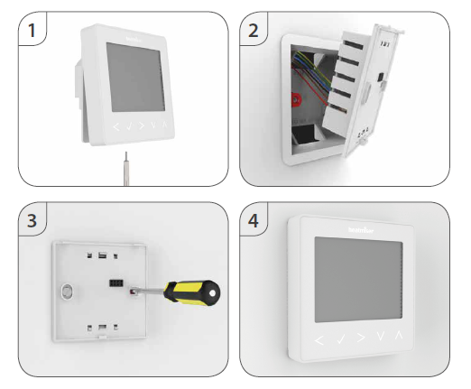
The neoStat V2 is designed to be flush mounted and requires a back box of 35mm (minimum depth) to be sunk into the wall before installation.
- Step 1 Using a small screwdriver, slightly loosen the screw from the bottom face of the thermostat. Then carefully separate the front half from the back plate.
- Step 2 Place the thermostat front somewhere safe. Terminate the thermostat as shown in the diagrams on pages 28-31 of this booklet. Note: For time clock wiring connections, terminate as shown on page 38.
- Step 3 Screw the thermostat back plate securely into the back box.
- Step 4 Clip the front of the thermostat onto the back plate, securing it in place with the retaining scre
System Type
‘System Type’ makes sure that the thermostat operation and switched outputs are configured to the correct installation.
- Key: NO = Normally Open Switch, NC = Normally Closed Switch
- GND and AO = 0-10 Volt Fan Output.
01= 2 Pipe System Manual Select Heat or Cool
- Heat, Cool & Ventilation modes both with 3 speed fan and Normally Open, Normally
- Closed valve connection method.
- Heat = Auto & Manual fan. Terminal Outp uts Fan: ‘GND’, ‘AO’
- Cool = Auto & Manual fan. Valve: ‘V1’ = NO, ‘V2’ = NC.
- Vent = Manual 3 speed selectable fan.
02 = 2 Pipe System Cool Only
- Cool and Vent options only, with 3-speed fan and Normally Open, Normally Closed connection method.
- Cool = Auto & Manual fan. Terminal Outputs Fan: ‘GND’, ‘AO’
- Vent = Manual 3-speed selectable fan. Valve: ‘V1’ = NO, ‘V2’ = NC.
03 = 2 Pipe System Manual Select Heat or Cool (Twin Valve output)
- Heat, Cool, & Ventilation modes with 3 speed fan (Cool & Vent only) and twin valve outputs.
- Cool = Auto & Manual fan for cooling only! No fan output for heating.
- Vent = Manual 3-speed selectable fan.
- Terminal Outputs Fan: ‘GND’, ‘AO’
- Valve: ‘V1’ for ‘Cooling’.
- Valve: ‘V2’ for ‘Heating’.
04 = 4 Pipe System Heat, Cool, and Auto
- Heat, Cool, Auto & Ventilation modes with 3 speed fan (all modes) and twin valve outputs.
- Heat, Cool, Auto = Auto & Manual fan. Terminal Outputs Fan: ‘Hf’ ‘Mf’ ‘Lf’
- Vent = Manual 3 speed selectable fan. Valve: ‘V1’ for ‘Cooling’.
- Valve: ‘V2’ for ‘Heating’.
05 = 2 Pipe System Heat, Cool with 2 stage heating.
- Heat, Cool & Ventilation modes with 3 speed fan (all modes) and 2 stage heating output.
- 1st stage Heat = No Fan Terminal Outputs Fan: ‘Hf’ ‘Mf’ ‘Lf’
- 2nd stage Heat = Auto & Manual fan. Valve: ‘V1’ for ‘Cooling’ &
- Cool = Auto & Manual fan. 2nd stage heating.
- Vent = Manual 3 speed selectable fan. Valve: ‘V2’ for ‘Heating’.
To select the desired ‘System Type’…
- Use the ‘Left/Right’ arrow keys to highlight then press
 and hold the Tick button for 3 seconds to turn off the display………………………………………………………..
- Press Tick to enter ‘Setup’ …………………………………………………………………………………………………………………….

- Repeatedly press the ‘Up’ key until you see ‘10’ displayed top right of the screen………………….

- The large 2 digit number now represents the ‘System Type’.
- Use the ‘Left/Right’ arrow keys to select the desired type from the list above ………………….

- Press Tick to confirm selection …………………………………………………………………………………………………………..
Pairing the neoHub

- Connect the neoHub to your router with the Ethernet cable provided.
- Connect the power supply to the neoHub.
- The router will automatically assign an IP address to the neoHub, the Link LED will light up RED once the neoHub has connected to your network.
- Once connected to the Heatmiser cloud server, the Link LED will turn GREEN.
- Connect your smartphone or tablet device to the same WiFi network as your router.
- Download the FREE Heatmiser neoApp from the Apple App Store or Google Play Store and register an account.
- Once you have registered your account, press Sign In, then press Add Location.
- Press the connect button on the neoHub to add the location to your account.
- When successfully connected, enter a title for the location (e.g. Home)
Pairing the neoStat-HC1
- On the neoStat-HC1, use the Left / Right keys to select, press and hold Tick ………..
- SETUP will be highlighted, now press the Tick key once …………………………………………….
- Feature 01 is displayed on the screen.
- Pairing the neoStat-HC1
- Press the Tick key once again to pair the neoStat to the neoHub …………………….
- The symbol appears flashing on the display.
- When the neoStat-HC1 successfully connects to the neoHub the symbol will be permanently displayed
- In the app, Press ADD ANOTHER for additional zones or press FINISH to complete setup
What is a Mesh Network?
NeoStats work using a mesh network, meaning neoStats can send & receive signals via other thermostats on the network. This signal is relayed from one thermostat to another until it reaches its destination. This communication method extends the communication range whilst offering increased network stability when compared with standard RF thermostats. The Mesh symbol is shown when the device is communicating with the neoHub, if the mesh symbol disappears this indicates a connection to the neoHub has been lost.
Approach Sensor
The neoStat V2 uses proximity to detect when you are about to use the touch keys. As you approach the neoStat V2, the touch keys and backlight will light up. This can be useful if you need to adjust the set temp or timer in a dark room.
LCD Display
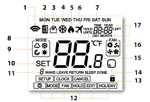
- Mesh Symbol – Displayed when connected to the neoHub.
- Window Icon – Displays when Window/Door Switch is triggered.
- Frost Protection/Standby – Displayed when frost protection is enabled.
- Cool Symbol – Displayed when cooling is active.
- Flame Symbol – Displayed when the thermostat is calling for heat and ashes when optimum start is active.
- Holiday – Displayed when the thermostat is in holiday mode.
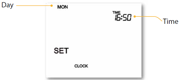
- Day Indicator – Displays the day of the week.
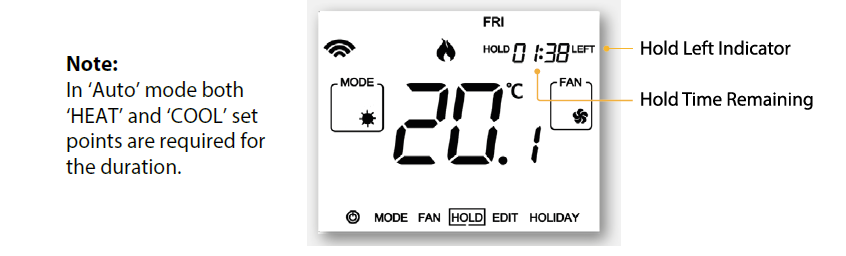
- Until/Hold – Displayed when the neo-HC1 has been manually overridden to the next programmed comfort level, or held to a certain temperature for a select period.
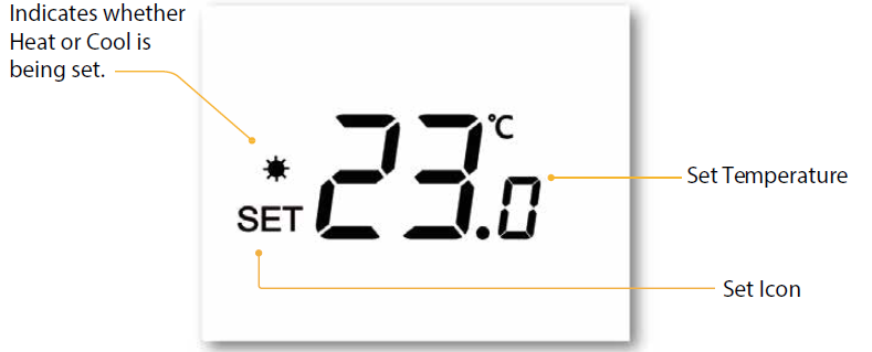
- Mode Indicator – Displays current mode of operation (Auto, Heat, Cool, Ventilation). 10. Set – Displays when changes are being made to the conguration and current set temperature points.
- Program Indicator – Displayed during programming to show which period is being altered.
- Main Menu – Highlighted text indicates selected option.
- Keypad Lock Indicator – Displayed when the keypad is locked.
- Sensor Warning – Flashes on screen when the thermostat has failed to receive a signal from a Wireless Sensor or Window Switch.
- Temperature – Displays the ambient room temperature in Celsius or Fahrenheit.
- Fan Icons – Static display icon when the fan is activated andashes while selecting the desired fan speed.
- Time/Day/Month/Year – Displays when setting the Clock/Calendar or a Holiday period
Temperature Display
Neo-HC1’ will always show the ambient room temperature. If wireless remote sensors are paired, (‘neohub’ required) the display will automatically show an average temperature between both sensors.
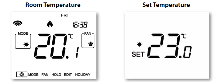
To view the set temperature (Heat or Cool modes only):
- Press either the ‘Up’ or ‘Down’ arrow key once …………………………………………………………………..

- Press tick to return to main screen……………………………………………………………………………………….
To view the set temperatures for (Auto Heat/Cooling):
- Use either the ‘Up’ or ‘Down’ arrow key once to view ‘HEAT/COOL’ set temp……………….
- Note: The temperature that shows first is determined by the mode that is currently active.
- Press tick to view the next set temperature ……………………………………………………………………….
- Press tick a second time to return to main screen……………………………………………………………..
- The ‘SET’ screen will timeout after 5 seconds if the tick button is not pressed
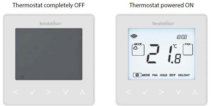
Power On/Off
- The heating is indicated ON when the flame icon is displayed.
- When the flame icon is absent, there is no requirement for heating to achieve the set temperature but the neoStat remains active.
- To turn the neoStat V2 off completely, scroll to the Power Icon and hold the Tick key for approximately 3 seconds until the display goes blank …………………
- The display and heating output will be turned OFF.
- To turn the thermostat back ON, press the Tick key once…………..
Setting The Time And Date
- Use the Left / Right keys to scroll to ……………………………………………………………………………….
- Press and hold Tick to turn off the display ………………………………………………………………………….
- Use the right arrow key to select CLOCK……………………………………………………………………………..

- Press Tick to confirm selection………………………………………………………………………………………………
- Use Up / Down keys to set the year………………………………………………………………………………………
- Press Tick to confirm selection ……………………………………………………………………………………………..
- Repeat the steps to set the Month, Date & Time ………………………………………………………………
- Press Tick to confirm the new clock settings………………………………………………………………………
- Use the down arrow to scroll to ……………………………………………………………………………………….
- Press Tick to turn the display on …………………………………………………………………………………………..
Mode Select
Neostat-HC’ can be used as a heating/cooling thermostat and a fan ventilation controller, (mode options dependent on ‘System Type’ pages 5 & 6).
To select the mode:
- Use the ‘Left/Right’ keys to scroll to ‘MODE’ then press Tick…………………..
- Repeatedly press the Tick key to select the mode…………………………………..
Fan Speed
NeoStat-HC’ allows for manual or automatic fan control for both heating and cooling. When set to manual there are 3 options, ‘Low’, ‘Medium’ & ‘High’. In auto, the thermostat will choose the correct fan speed dependent on set temperature to actual temperature difference.
- 3°C/6°F = High Fan 2°C/4°F = Medium Fan 1°C/2°F = Low Fan
To select the fan speed:
- Use the ‘Left/Right’ keys to scroll to ‘FAN’ then press Tick……………………….
- Repeatedly press the Tick key to select the speed…………………………………..
Setting the Comfort Levels
The ‘neoStat-HC’ offers three program mode options; Weekday/Weekend, 7 Day and 24 Hour programming. There is also the option to use the ‘neoStat-HC’ as a manual thermostat. The thermostat is supplied with comfort levels already factory programmed, but these can be changed easily.
The default times and temperature settings are;
- Heating defaults
- 07:00 – 21°C (Wake) 09:00 – 16°C (Leave) 16:00 – 21°C (Return) 22:00 – 16°C (Sleep)
- Cooling defaults
- 07:00 – 23°C (Wake) 09:00 – 26°C (Leave) 16:00 – 23°C (Return) 22:00 – 26°C (Sleep) Time input for unused levels must be set to –:– so that the ‘neoStat-HC’ will skip these and continue on to the next programmed time.
Auto Mode
In ‘Auto’ mode you will set both ‘HEAT’ and ‘COOL’ set points for each level. To disable cooling for a particular level, adjust the ‘COOL’ set point by a continual press of the ‘Up’ key until the display shows —
- To program the comfort levels, use the Left / Right keys to scroll to EDIT…………………..
- Press Tick to confirm selection …………………………………………………………………………………………….
- Use the Left / Right keys to select day / period of week (the selection will flash)………
- Press Tick to confirm selection …………………………………………………………………………………………….
- WAKE will now flash and the current time and temperature setting will be shown.
- Press Tick to alter WAKE settings………………………………………………………………………………………….
- Use the Up / Down keys to set the hours then tick to confirm………………………………………
- Use the Up / Down keys to set the minutes then tick to confirm………………………………….
- Use the Up / Down keys to set the temperature………………………………………………………………
- Press Tick to confirm the settings…………………………………………………………………………………………
- Note: At this stage in ‘Auto’ you will be prompted to enter the ‘COOL’ temperature immediately following the ‘HEAT’ input.
- Press Tick to confirm the settings…………………………………………………………………………………………
- Press the right arrow key……………………………………………………………………………………………………….
- ‘LEAVE’ will now flash and the current settings will be displayed.
- Tip: In ‘Auto’ mode you can quickly glance at both ‘HEAT’ & ‘COO L ‘ temperatures by pressing the ‘Up/Down’ keys while the selected level is flashing.
- Press Tick to alter ‘LEAVE’ settings ……………………………………………………………………………………….
- Repeat these steps to set all comfort levels. For any unused periods set time to –:–
- Use the Left / Right keys to scroll to DONE and press Tick………………………………………………
Manual Temperature Control
The ‘Up/Down’ keys allow you to adjust the current set temperature. When you press either key, you will see the word ‘SET’ and the desired temperature value.
- Use the ‘Up/Down’ keys to adjust the ‘SET’ value………………………………………………..
- Press Tick to confirm settings and return to the main display …………………………
In ‘Auto’ mode you are required to set both ‘Heat’ and ‘Cool’ temperatures!
Temperature Hold
- Use the Left / Right keys to scroll to HOLD……………………………………………………….
- Press Tick to confirm selection …………………………………………………………………………………….
- Use the Up / Down keys to set the desired Hold period …………………………………
- Press Tick to confirm selection …………………………………………………………………………………….
- Use the Up / Down keys to set the desired Hold temperature ………………………
- Press Tick to confirm selection …………………………………………………………………………………….
Locking /Unlocking
Locking the neoStat-HC1
- Use the ‘Left/Right’ keys to scroll to ‘HOLD’ & press for 10 seconds………
- The display will show 0000. At this point enter a four-digit PIN.
- Use the Up / Down keys to enter the first two digits …………………………………..
- Press to confirm ……………………………………………………………………………………………………
- Use the Up / Down keys to enter the second two digits …………………………….
- Pres to confirm ……………………………………………………………………………………………………
- The display will return to the main screen and display the keypad lock indicator

Unlocking the neoStat-HC1
- Use the Up / Down and keys to enter the first two digits……………………….
- Use the Up / Down and keys to enter the second two digits ……………….
Frost Protection/ Standby
- Use the Left / Right keys to scroll to the Power Icon ………………………………………………..

- The frost icon will toggle ON/OFF each time Tick is pressed ……………………………………………
In this mode, the ‘neoStat-HC’ will display the frost icon and will only turn the heating ON should the room temperature drop below the set frost temperature. If the heating is turned ON whilst in frost mode, the flame symbol will be displayed.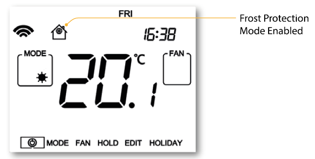
- To cancel the frost protect mode, navigate to the Power button again and press
- Tick………………………………………………………………………………………………………………………………………………..
Holiday
In thermostat mode, the holiday function reduces the set temperature in your home to the frost protection temperature setting (see page 23). The thermostat will maintain this temperature for the duration of the holiday and will then automatically return to the program mode on your return. In time clock mode, the holiday function maintains the timed output as OFF. Set a date & time for the holiday period to end, using the steps below
- Use the Left / Right keys to scroll to HOLIDAY and press Tick ……………………….
- Use the Up / Down keys to set the year …………………………………………………………………
- Press Tick …………………………………………………………………………………………………………………………….
- Use the Up / Down keys to set the month……………………………………………………………..
- Press Tick …………………………………………………………………………………………………………………………….
- Repeat the steps to set the Date & Time…………………………………………………………………
- Pressing Tick to confirm selection…………………………………………………………………………………..
cancel holiday
- Use the Left / Right keys to scroll to HOLIDAY and press Tick …………………………….
- CANCEL will be highlighted, Press Tick to cancel ………………………………………………………..
Ventilation Mode
In ventilation mode there is no heat or cool output only fan control. With no timer setting this mode is completely manual and is available in all ‘System Types’.
To select ‘VENT’ mode:
- Use the ‘Left/Right’ keys to scroll to ‘MODE’ then press Tick…………………………………
- Repeatedly press the Tick key to select
 ………………………………………………………………………
Fan Icons
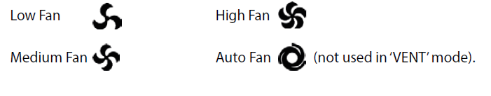
- Low Fan
- High Fan
- Medium Fan
- Auto Fan
To start/stop or change fan speed.
- Use ‘Left/Right’ keys to highlight ‘FAN’……………………………………………………………………………….
- Repeatedly press the Tick key to select between low, medium, high or off………………
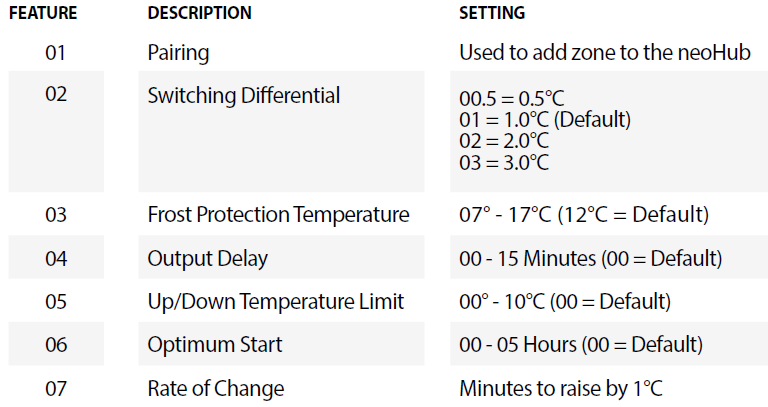
- Feature 01 – Pairing To neoHub: This function is used to pair the thermostat to the Hub.
- Feature 02 – Switching Dierential: This function allows you to increase the switching differential of the thermostat. The default is 1°C which means that with a set temperature of 20°C, the thermostat will switch the heating on at 19°C and of at 20°C. With a 2°C dierential, the heating will switch on at 18°C and of at 20°C.
- Feature 03 – Frost Protect Temperature: This is the temperature maintained when the thermostat is in Frost Mode. The range is 07 – 17°C. The default is 12°C and is suitable for most applications.
- Feature 04 – Output Delay: To prevent rapid switching, an output delay can be entered. This can be set from 00 – 15 minutes. The default is 00 which means there is no delay.
- Feature 05 – Temperature Up/Down Limit: This function allows you to limit the use of the up and down temperature arrow keys. This limit is also applicable when the thermostat is locked and so allows you to give others limited control over the heating system.
- Feature 06 – Optimum Start: Optimum start will delay the start up of the heating system to the latest possible moment to avoid unnecessary heating and ensure the building is warm at the programmed time. The thermostat uses the rate of change information to calculate how long the heating needs to raise the building temperature 1°C (with a rate of change of 20, the thermostat has calculated the heating needs 20 minutes to raise the building temperature 1°C) and starts the heating accordingly
- Feature 07 – Rate of Change: Number of minutes for 1°C temperature rise.
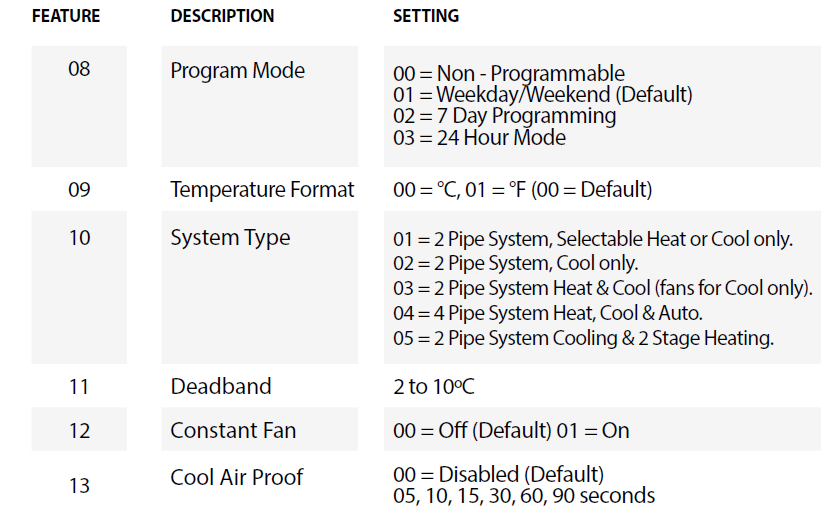
- Feature 08 – Program Mode The neoStat-HC1 offers the following program mode options;
- Feature 09 – Temperature Format: This function allows you to select between °C and °F.
- Feature 10 – System Type: Congures the thermostat settings and switched outputs to best suit the heat and cool sources installed.
- Feature 11 – Deadband: Only selectable when ‘Auto’ (HEAT & COOL) mode is enabled. Deadband is the temperature difference between the ‘HEAT’ and ‘COOL’ set points. This is to prevent heating and cooling operating at the same time working against each other. Example, ‘HEAT’ set point at 20°C with a Deadband of 2°C, the minimum allowed ‘COOL’ set point would be 23°C. This means that if ‘COOL’ was set to 22°C it would push the ‘HEAT’ set point to 19°C.
- Feature 12 – Constant Fan: Fan will automatically run between ‘Low’, ‘Med’ & ‘High’ while there is a demand for heat or cool. When demand has stopped, the fan will continually run but in ‘Low’ speed only. If ‘Constant Fan’ is disabled, the fan will go of completely when heat or cool demand has ended. Note: this feature is disabled in heating mode when ‘System Type’ is set to 03 = ‘2 Pipe System Heat or Cool Only’.
- Feature 13 – Cool Air Proof: To avoid blowing the cold air from fan coil when the thermostat requires heating, the coil valve will open for the set duration before fan starts blowing. Set range in seconds: 0 ,5,10,15, 30, 60, 90. Default value=0 (disabled).
Adjusting the Feature Menu Settings
- Use the Left / Right keys to scroll to ……………………………………………………………
- Press and hold the Tick button for 3 seconds ………………………………………………..
- SETUP will be highlighted, now press the tick key once……………………………….
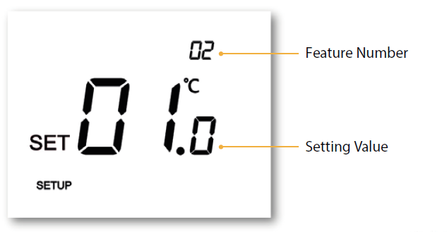
- Use the Up / Down keys to scroll through features ……………………………………….
- Use the Left / Right keys to adjust the setting within each feature …………….
- Press Tick to confirm and exit setup menu ……………………………………………………..
Re-calibrating the Thermostat
- Use the Left / Right keys to scroll to the …………………………………………………..
- Press and hold Tick to turn the display OFF ………………………………………………….
- Press and hold the Tick and Down keys together for 10 seconds ……………..
- The current temperature will appear on the display.
- Use the Up / Down keys to configure the new temperature value ………….
- Press the Tick key to confirm the change and the display will go blank….
- Press the down arrow to highlight the …………………………………………………….
- Press the Tick key once to turn the thermostat ON…………………………………….
Error Codes
The neoStat-HC will display an error code if there is a fault with the temperature sensor. E0 = The internal sensor has developed a fault.
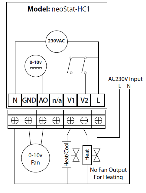
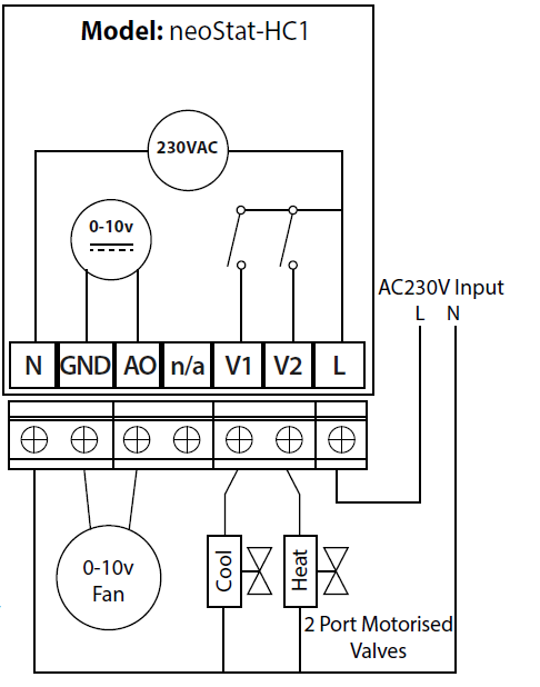
Wiring Diagram

Normally Closed Valve

Normally Open Valve
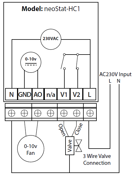
3 Wire Valve Connection
Fan Coil & Wet Systems
Factory Reset
To reset the device to factory default settings, follow these steps:
- Use the Left / Right keys to scroll to …………………………………………………………….
- Press and hold Tick to turn the display OFF ……………………………………………………
- SETUP will be highlighted …………………………………………………………………………………
- Press and hold the Tick key for 10 seconds ……………………………………………………..
- All of the icons on the display will appear for 2 seconds, then you will see the number 1 or 2 flashing.
- Use the Left / Right keys to scroll between modes (selection will flash) …….
- Mode 1 = Thermostat
- Mode 2 = Time Clock
- Press the Tick key to confirm selection ……………………………………………………………
- The neoStat will revert to the main display screen for the selected mode.
Heatmiser
Want More Information?
Call our support team on: +44 (0)1254 669090 Or view technical specifications directly on our website: www.heatmiser.com
- Heatmiser UK Ltd
- Units 1-5 Hurstwood Court, Mercer Way
- Shadsworth Business Park, Blackburn,
- Lancashire, BB1 2QU, United Kingdom
- Twitter: @heatmiseruk
- Facebook: facebook.com/thermostats
Reference
Download manual:
Heatmiser neoStat-HC1 -0-10v Smart Fan Coil Thermostat USER MANUAL
Other Manual:
Heatmiser neoStat HC1 / 0-10v Smart Fan Coil Thermostat PRODUCT SPECIFICATION GUIDE
![]()
Heatmiser neoStat-HC1 -0-10v Smart Fan Coil Thermostat USER MANUAL
Leave a Reply