
Fujitsu UTY-RSNUM Simple Wired Remote Installational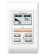
SAFETY PRECAUTIONS
- Let the customer keep this installation manual because it is needed when the air conditioner or remote controller is serviced or moved.
WARNING
This mark indicates procedures which, if improperly performed, might lead to the death or serious injury of the user.
- For the air conditioner to operate satisfactorily, install it as outlined in this installation manual.
- Installation work must be performed in accordance with national wiring standards by authorized personnel only.
- Do not turn on the power until all the installation work is complete.
CAUTION
This mark indicates procedures which, if improperly performed, might possibly result in personal harm to the user or damage to property.
- Do not wire the remote controller cable and the bus wire together with or parallel to the connection cables, transmission cables, and power supply cables, of the indoor and outdoor units. It may cause erroneous operation.
- When installing the bus wire near a source of electromagnetic waves, use shield wire.
- Do not set the DIP switches, either on the air conditioner or the remote controller, in any way other than indicated in this sheet or the manual that is supplied with the air conditioners. Doing so may result in an accident.
ACCESSORIES
The following installation parts are supplied. Use them as required.
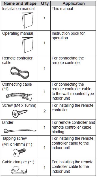
Use only if the remote controller cable must be modified for the indoor unit model.
ELECTRICAL REQUIREMENT
When connecting the remote controller use the following wiring.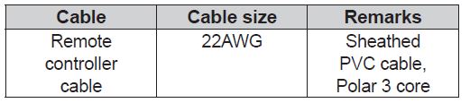
We recommend that you purchase our service parts for the remote controller cable. Contact service personnel to purchase this.
SELECTING AN INSTALLATION LOCATION
Dimensions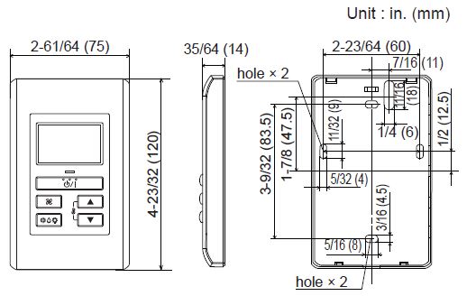
Name of parts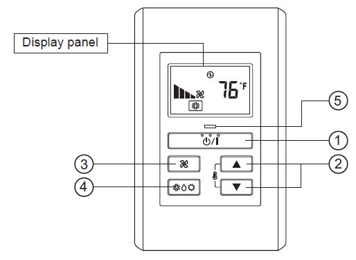
Display panel
- “
 ” (START/STOP Button)
 - “
 ” , “
” , “  ” (Set Temperature Button)
 - “
 ” (Fan Control Button)
 - “
 ” (Operation Mode Button)
 - Operation Lamp Display
- Electric energy Display
- Standby Display
- Operation Lock Display
- Fan Speed Display
- Temperature Display
- Error Display
- Operation Mode Display
INSTALLING THE REMOTE CONTROLLER
Installation
Insert the end of a fl at blade screwdriver at the arrow parts of the groove at the side of the remote controller case and remove the remote controller case top by turning the screwdriver.
- When remote controller cable exposed
- Use a tool to cut away the thin area on the upper center of the front case (indicated by in Fig. 1).
- Connect the remote controller cable to the remote controller terminal board specifi ed in Fig. 2.
- Clamp the remote controller cable sheath with the binder as shown in Fig. 2.
- Cut off the excess binder.
- Install the rear case to the wall, etc., with two screws. (Fig. 3)
- When remote controller cable embedded
- Embed the remote controller cable and box.
- Pass the remote controller cable through the hole in the rear case and connect the remote controller cable to the remote controller terminal board specifi ed in Fig. 2.
- Clamp the remote controller cable sheath with the binder as shown in Fig. 2.
- Cut off the excess binder.
- Install the rear case to the wall, box, etc., with two screws. (Fig. 3)
CAUTION
Do not touch the remote controller PC board and PC board parts directly with your hands.
SETTING THE DIP SWITCHES
Set the remote controller DIP switches. (Fig. 4)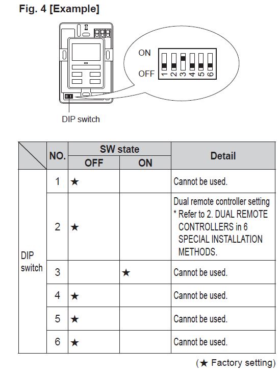
Connection of Remote Controller Cable
CAUTION
When connecting the remote controller cable (cord) to the wall mounted type indoor unit, do not connect it to the outdoor unit or the indoor unit power terminal block. It may cause a failure.
There are 2 methods to connect the remote controller cable to the indoor unit. One is the connection using contained connecting cable, and the other is the connection the remote controller cable is connected to the exclusive terminal block of the indoor unit. Exclusive terminal block for remote controller connection method is different depending on each model. Modify the remote controller cable as per below description and connect it. (For the details, refer to the installation manual of the indoor unit to be used.)
When connecting to the connector
Connect the remote controller cable to the connecting cable, and insert it to the connector.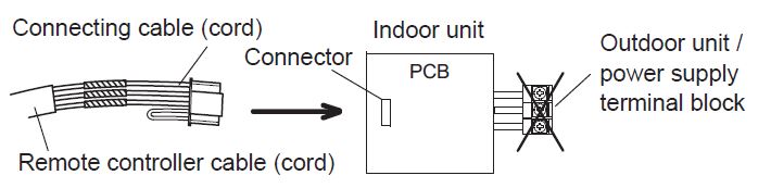
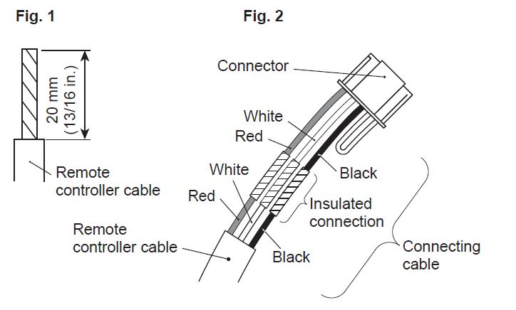
Modify the cable as per below methods.
- Use a tool to cut off the terminal on the end of the remote controller cable, and then remove the insulation from the cut end of the cable as shown in Fig. 1.
- Connect the remote controller cable and connecting cable as shown in Fig. 2.
- Be sure to insulate the connection between the cables.
When connecting to exclusive terminal block
Connect the end of remote controller cable (cord) directly to the exclusive terminal block.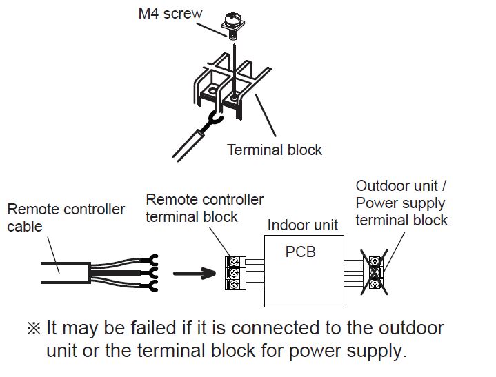
It may be failed if it is connected to the outdoor unit or the terminal block for power supply.
INSTALLATION METHODS
Group control
- A number of indoor units can be operated at the same time using a single remote controller.
- Depending on the model, some indoor units cannot be connected for group control. (Option is not available for wall mounted type indoor unit.)
- Some functions may become unusable, depending on the combination of the indoor units that are connected in a group.
- Wiring method (indoor unit to remote controller)
EXAMPLE: Single Type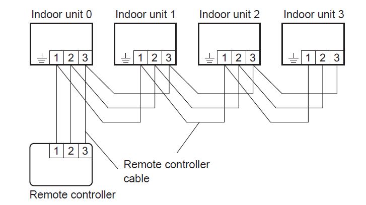
- Indoor unit address setting Set each indoor unit address using the DIP switch of each indoor unit. (Refer to the installation manual for the indoor unit.)
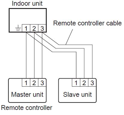
Dual remote control
- Depending on the model, some indoor units cannot
be connected for dual remote controllers. (Option is
not available for wall mounted type indoor unit.) - Two separate remote controllers can be used to
operate the indoor units.
- Wiring method (indoor unit to remote controller)
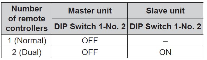
- Remote controller DIP switch 1 setting Set the remote controller DIP switch 1-No. 2 according to the following table.
TURNING ON THE POWER
CAUTION
Recheck the wiring. Incorrect wiring will cause trouble.
- Check the remote controller wiring and DIP switch settings.
- Check the indoor and outdoor unit wiring and circuit board switch settings, and then turn on the indoor and outdoor units.
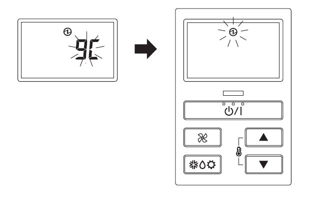
- If the power source is connected correctly, the mark will be displayed in the center of the remote controller display. After “
 ” has flashed on the set temperature display for several second, the mark will be displayed in the center of the remote controller display.
- For the wiring and circuit board switch settings method, refer to the installation manual for the indoor unit and outdoor unit.
- For the wiring and circuit board switch settings method, refer to the installation manual for the indoor unit and outdoor unit.
FUNCTION SETTING
This procedure changes the function settings used to control the indoor unit according to the installation conditions. Incorrect settings can cause the indoor unit to malfunction. Perform the “FUNCTION SETTING” according to the installation conditions using the remote controller.
- Refer to the indoor unit installation manual for details on the function numbers and setting numbers.
- Prepare for setting of indoor unit referring to installation manual of indoor unit before start of functional setting.
Start of Function setting mode
- Press the “ ” button, “ ” button and “
 ” button for more than 5 seconds simultaneously. Then shift to Function setting mode.
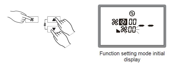
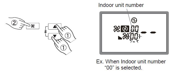
- Press the “ ” button or “ ” button and select the Indoor unit number. Then press the “ ” button.
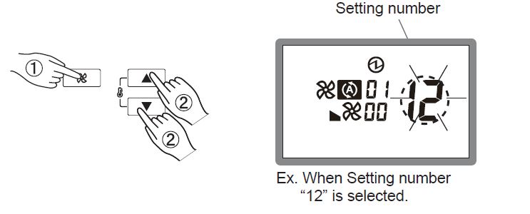
Function number and setting number setting - “Function number” display blinks. Then display Number by pressing the “ ” button or “ ” button.
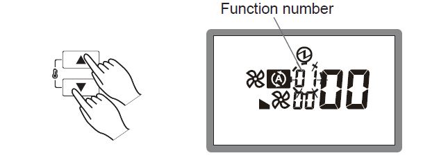
- When the “Setting number” blinks by pressing the “ ” button set the Setting number by pressing the “ ” button or “ ” button.
- Fix the setting by pressing the “
 ” button. (Data is transferred to the indoor unit).(– is displayed,) if not set the indoor unit.
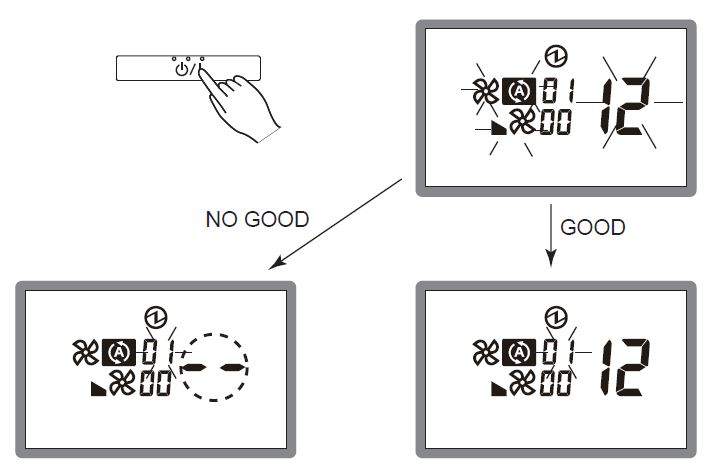
- Set again as per procedures 3-5 above.
- When set properly in the indoor unit.
Completion of address setting mode
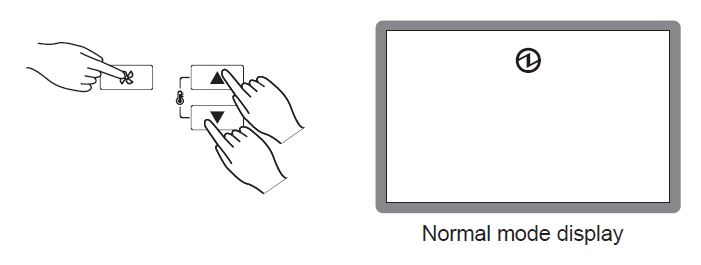
- Function setting mode is released and returns to normal display if the “ ” button, “ ” button and “ ” button are pressed for more than 5 seconds simultaneously.
- Function setting mode is released automatically if no key is pressed for 60 seconds even the above buttons are not pressed. (Switch to Function setting mode as per procedure 1 above. It is automatically released when Function setting)
- Function setting mode is released automatically if no key is pressed for 60 seconds even the above buttons are not pressed. (Switch to Function setting mode as per procedure 1 above. It is automatically released when Function setting)
- After completing the FUNCTION SETTING, be sure to turn off the power and turn it on again.
Note:
Function Setting is available for Master remote controller only.
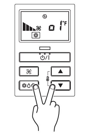
TEST OPERATION
- If the operation lamp is on, press the “ ” button to turn it off.
- Press the “
 ” button and the “ ” button at the same time for more than 2 seconds to start the test operation. The operation lamp will light up and “ ” will be displayed on the set temperature display.
 - To stop the test operation, press the “ ” button.
- The “ ” button or “ ” button do not function. However, the other buttons can be used to change the settings.
- Test operation is used for constrained operation of the outdoor unit.
- The “
Note:
When “ ” is indicated on temperature display, it means under maintenance. Indoor unit cannot be operated.
FILTER LAMP RESET
Some indoor unit models are equipped with a fi lter lamp in the indoor unit display to indicate when it is time to clean the air filters. Press the “ ![]() ” button for 2 seconds or more. The indoor unit fi lter lamp will go off and the fi lter display will disappear.
” button for 2 seconds or more. The indoor unit fi lter lamp will go off and the fi lter display will disappear.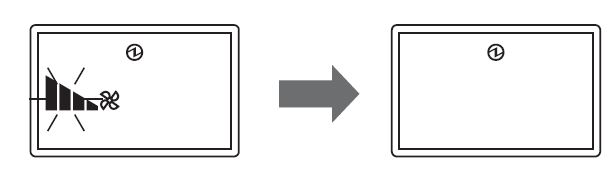
ERROR CODE DISPLAY
If there is a problem with the air conditioner, “ ![]() ” will be displayed.
” will be displayed.
If “ ![]() ” is displayed, immediately contact authorized service personnel. Do not used the operation below if an error has occurred.
” is displayed, immediately contact authorized service personnel. Do not used the operation below if an error has occurred.
When 0-15 is indicated on the Faulty unit No., error has occurred at the indoor unit. Refer to the indoor unit installation manual.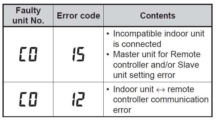
Leave a Reply