
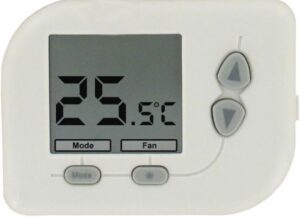
DWYER PLVT1 Digital Programmable Thermostat
Installation Location
The thermostat should be mounted on an inner wall 1.5m above the floor in position where it is readily affected by changes of the general room temperature with freely circulating air. Prevent direct exposure to sunlight; dripping or splashing area. Do not place this unit at a location where air circulation is low, or where it has great temperature changes (e.g. near door). Do not place the thermostat near heat generating sources (radiators, hot air vents, TV or lights).
Wiring
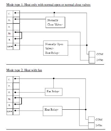
For Model PLVT1, there are 6 wiring terminals at the back of the thermostat which are labeled as “C”, “Y” and “G”, “Rc”, “R” and “O/W B”.
Mounting
- Ensure the surface is level.
- Place the cables at the hole near the terminal block.
- Insert 2 pcs of wall anchors into the holes of the wall.
- Fasten the thermostat with 2 pcs of long screws through the 2 mounting holes.
B. Start/Reset:
- When the system is reset, all the LCD segments are ON and the measured temperature will be displayed after a while.
- Low Battery Check will be done at startup. displays when battery is low.
- Latch relay will be turned off at startup.
Normal Display Mode:
- Temperature detection starts and LCD displays the room temperature.
- In Heat or Auto mode, defrost function is activated with displayed when temperature is below 5°C / 40°F. Heater is on regardless of the setting temperatures.
- Below 0°C/ 32°F, Model PLVT1 will display LO.
- Above 40°C/ 99°F, Model PLVT1 will display HI.
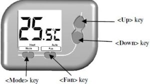
- Press <Up>/ <Down> to adjust heat/ cool setting temperature.
- Press <Mode> to select heat/ cool/ auto/ off mode.
- Press <Fan> to select fan on/ auto
Temperature Setting Display Mode:
To adjust heat/cool setting:
- Press <Up> or <Down> keys to adjust heat/cool setting temperature in normal display mode.
- Heat/ Cool setting temperature flashes.
- In Heat mode, only heat setting temperature can be adjusted.
- In Cool mode, only cool setting temperature can be adjusted.
- In Auto mode, heat and cool setting temperature can be adjusted.
- In Off mode, no setting temperature can be adjusted.
- Press <Mode> key to exchange the heat and cool setting temperature in auto mode.
- The operation will resume to normal display mode after no key is pressed for 10’s.
Internal Mode Setting Display:
- To adjust the internal setting of Model PLVT1
Mode Type Selection
- Press and hold <Mode> and <Up> keys for 2’s.
- LCD changes to the display of Mode type selection The letters represent Mode type.
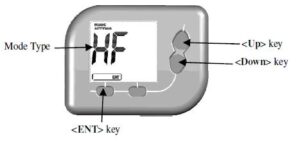
- Press <Up>/ <Down> to adjust Mode type.
- Press <ENT> to select Mode type and return to normal display mode.
Function Setting Selection
- Press and hold <Fan> and <Down> keys for 2’s.
- LCD changes to the display of Function setting selection.

- The left letters represent Function type; the right letters represent Setting.
- Press <Up>/ <Down> to adjust Function type/ Setting.
- Press <NEXT> to select Function type/ Setting.
- Press <ENT> to return to normal display mode.
Table of the Internal Setting
| Mode type | Function type | Setting | |||
|
HO |
Heat only (normal-open or normal-close valves) | HS | Span of Heater | 1 °C / 2°F | |
| 2 °C/ 4°F | |||||
| dU | Temperature Display Unit | °C | |||
| °F | |||||
|
HF |
Heat with fan |
HS | Span of Heater | 1 °C/ 2°F | |
| 2 °C/ 4°F | |||||
| dU | Temperature Display Unit | °C | |||
| °F | |||||
|
FC |
Fan Control method |
O | Gas or oil furnace – equipment controls fan | ||
| E | Electric furnace – thermostat controls fan | ||||
|
CL |
Cool |
dU | Temperature Display Unit | °C | |
| °F | |||||
| CS | Span of Cool | 1°C/ 2°F | |||
| 2°C/ 4°F | |||||
|
Cd |
Compressor Minimum-Off Delay |
1 | 1 minute compressor off delay | ||
| 2 | 2 minute compressor off delay | ||||
| 3 | 3 minute compressor off delay | ||||
| 4 | 4 minute compressor off delay | ||||
| 5 | 5 minute compressor off delay | ||||
|
HP |
Heat pump |
HS | Span of Heater | 1°C/ 2°F | |
| 2 °C/ 4°F | |||||
|
CO |
Changeover Valve |
C | O/B terminal energized in cooling
(default) |
||
| H | O/B terminal energized in heating | ||||
| dU | Temperature Display Unit | °C | |||
| °F | |||||
| CS | Span of Cool | 1°C/ 2°F | |||
| 2°C/ 4°F | |||||
|
Cd |
Compressor/ Heater Minimum-Off Delay |
1 | 1 minute compressor off delay | ||
| 2 | 2 minute compressor off delay | ||||
| 3 | 3 minute compressor off delay | ||||
| 4 | 4 minute compressor off delay | ||||
| 5 | 5 minute compressor off delay | ||||
|
SL |
Mode Adjustment |
1 | Heat, Cool Off Selectable | ||
| 2 | Auto, off Selectable | ||||
| 3 | Heat, Cool Off, Auto Selectable | ||||
|
HC |
Electric/oil/gas heat with cool (Default setting) |
HS | Span of Heater | 1°C/ 2°F (Default setting) | |
| 2 °C/ 4°F | |||||
| dU | Temperature Display Unit | ° C (Default setting) | |||
| °F | |||||
| CS | Span of Cool | 1°C/ 2°F (Default setting) | |||
| 2°C/ 4°F | |||||
|
Cd |
Compressor Minimum-Off Delay |
1 | 1 minute compressor off delay | ||
| 2 | 2 minute compressor off delay | ||||
| 3 | 3 minute compressor off delay | ||||
| 4 | 4 minute compressor off delay (Default setting) | ||||
| 5 | 5 minute compressor off delay | ||||
|
SL |
Mode Adjustment |
1 | Heat, Cool, Off Selectable | ||
| 2 | Auto, off Selectable | ||||
| 3 | Heat, Cool Off, Auto Selectable (Default setting) | ||||
|
FC |
Fan Control Method |
O | Gas or oil furnace – equipment controls fan | ||
|
E |
Electric furnace – thermostat controls fan
(Default setting) |
||||
Description of the mode types:
- Heat only ( normal-open or normal -close valves)
- Only Heat mode can be used for normal-open or normal -close valves, fan cannot be selected.
- Heat with fan
- Only Heat mode can be used, fan can be selected.
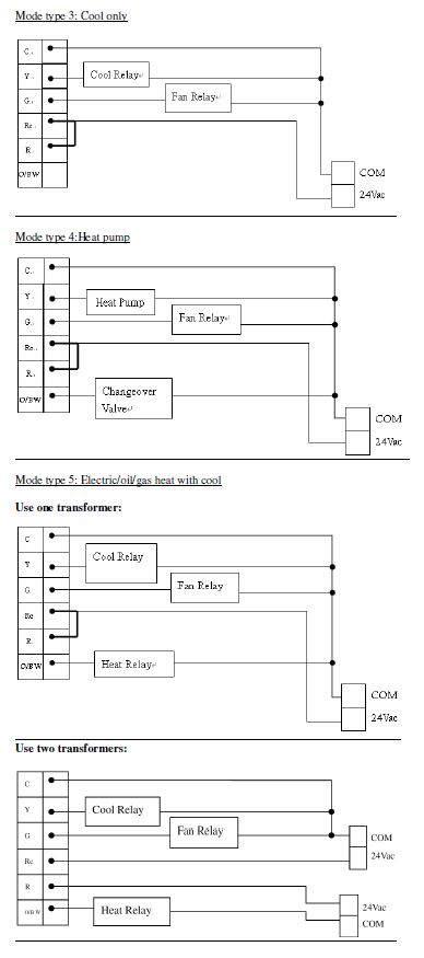
- Cool
- Only Cool mode can be used, fan can be selected.
- Heat pump
- Heat/ Cool/ Auto mode can be selected with changeover valve. (**While in auto mode. There is a Heat/Cool switching delay of 4 minutes to switch a heating system to cooling system or vice versa. During the period either Heater/Cooler or Fan will not turn on.)
- Electric/oil/gas heat with cool
- Heat/ Cool/ Auto mode can be selected. This is the default setting and common used in factories.
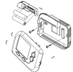
Replaceable Batteries Instruction:
- Batteries shall be installed with proper polarity and correct battery type.
- Do not use old and new batteries simultaneously.
- Batteries shall be removed if consumed or if product is to be left unused for a long time. Use 1.5V/cell alkaline batteries 2 pieces.
Maintenance
Caution: Switch off the electric source before maintenancing the thermostat. We recommend that the maintenance should be performed by trained personnel.
No heating/ cooling control
- Check the thermistor sensor performance by measuring the corresponding variable resistance under different temperatures. If it is in good condition and the
- LCD value will change accordingly, then trace the control circuit or the LCD connection, otherwise replace it.
- If the control circuit has a problem, replace the PCB if necessary.
Specification
- Temperature measurement: 0°C~40°C / 32°F ~ 99°F
- Accuracy: ±0.5°C/ 1°F
- Temperature Controllable range:
- Heat/Cool mode:
- Heat/Cool setting: 5°C~35°C / 40°F ~ 95°F
- Auto mode:
- Heat setting: 5°C~30°C / 40°F ~ 85°F
- Cool setting: 10°C~35°C / 50°F ~ 95°F
- Resolution: 0.5°C /1°F
- Power Supply: 24V~ +/-10% or 2 x AAA alkaline batteries
- Rating: 24V~ 50/ 60Hz 1A max
- Terminals: 2mm2 cable
- Operating temperature: 0 – 50 °C / 32 – 122 °F
- Storage temperature: -5 – 50 °C/ 23 – 122 °F
- Sensing Element: NTC thermistor
REFERENCE
DOWNLOAD MANUALS:
DWYER PLVT1 Digital Programmable Thermostat Installation Manual
![]()
DWYER PLVT1 Digital Programmable Thermostat Installation Manual
Leave a Reply