
Drayton Digistat +CRF 13616 Cylinder Thermostat
What is a cylinder thermostat?
….. an explanation for householders
A cylinder thermostat switches on and off the heat supply from the boiler to the hot-water cylinder. It works by sensing the temperature of the water inside the cylinder, switching on the water heating when the temperature falls below the thermostat setting and switching it off once this set temperature has been reached. Turning a cylinder thermostat to a higher setting will not make the water heat up any faster. How quickly the water heats up depends on the design of the heating system, for example, the size of the boiler and the heat exchanger inside the cylinder. The water heating will not work if a time switch or programmer has switched it off. And the cylinder thermostat will not always switch the boiler off, because the boiler sometimes needs to heat the radiators.
Cylinder thermostats are usually fitted between one-quarter and one-third of the way up the cylinder. The cylinder thermostat will have a temperature scale marked on it, and it should be set at between 60°Cc and 65°C, then left to do its job. This temperature is high enough to kill off harmful bacteria in the water, but raising the temperature of the stored hot water any higher will result in wasted energy and increase the risk of scalding. If you have a boiler control thermostat, it should always be set to a higher temperature than that of the cylinder thermostat. In most boilers, a single boiler thermostat controls the temperature of water sent to both the cylinder and radiators, although in some there are two separate boiler thermostats.
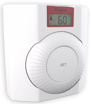
Your new thermostat with digital display.
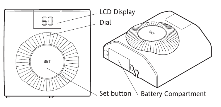
Thermostat Display – Features & Characters

FEATURES
This product has the following user-adjustable settings, Required temperature (temperature setpoint) and Minimum & Maximum temperature settings.
Simple Setting or Operating
To set the required temperature
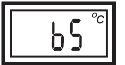
- The display normally shows the current setpoint.
- To adjust the required temperature, turn the dial clockwise to increase or anti-clockwise to decrease, (1 click = 5°C), the LCD will display the temperature setpoint as it is being adjusted, and ‘SET’ will be displayed. After a few seconds, the display will return to normal operation and will display the current setpoint.
ADVANCED FEATURES
To change the user-adjustable settings
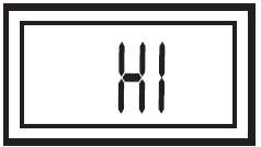
- To enter the ‘User’ menu, press and hold the “Set’ button for more than 5 but less than 10 seconds- the display will show Hi’ as shown,
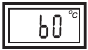
- If the dial is turned clockwise one click then ‘Lo’ (Minimum temperature setting) will be displayed and if turned one more click clockwise then ‘Hr’ (Maximum temperature setting) will be displayed.
Default Settings
- The maximum and minimum setpoints are preset in the factory to 65C and 60°C respectively.
Changing the Maximum Temperature Setting
- To adjust the maximum temperature setting enter the user menu as described above, then rotate the dial clockwise until “Hr’ is showing.
- Then press the ‘Set’ button once, and the current setting is shown.
- Rotate the dial clockwise to increase the maximum temperature setting (max. 70°C) and anti-clockwise to reduce the maximum temperature setting (min 40°C or min temp. setting). Press the ‘Set button to confirm, the display will show.
- Changing the Minimum Temperature Setting
- To adjust the minimum temperature setting enter the user menu as described above, then rotate the dial clockwise until ‘Lo is showing

- Then press the ‘Set’ button, the current setting is shown.
- Rotate the dial clockwise to increase the minimum temperature setting (max. 70°C or max. temp. setting) and anti-clockwise to reduce the minimum temperature setting (min 40°C). Press the ‘Set’ button to confirm, the display will show
While adjusting the settings within the menu, when you reach the maximum or minimum possible setting the display will flash to indicate you cannot adjust the product further To return to normal operation, either press the “Set’ button for more than 5sec or wait for 1 minute and it will return automatically.
SCR RECEIVER
SCR (Receiver) Normal Operating Mode
- Once the Wireless System’ has been commissioned, there should be little need for any user interaction with the SCR.
- During normal operation the red and green LEDs will occasionally be on, these signify the following:
- Green LED
The green LED will be on when there is a demand for heating, and off when there is no demand. - Red LED
The red LED will flash for 7 seconds, approximately every 5 minutes. This denotes that a radio signal is being received from the Digistat+C RF unit.
- Green LED
Situations Requiring Attention
Red LED continually flashing
This denotes that the batteries in the Digistat+C RF unit are approaching the end of their life (see “battery replacement).
Red LED is continually on
- This denotes that the SCR has been unable to receive a radio signal from the Digistat+C RF unit. This may be caused by the batteries being dead (see “battery replacement) or some temporary interference with the radio signal
- To resend and test the signal, go to the Digistat+C RF unit and open the battery drawer, after a few seconds (the display will go blank) close the battery drawer and then reset to your desired temperature. If the radio signal has been successfully transmitted and received, the red LED will flash for 7 seconds and then go off.
- If the red LED stays on, there may be some other fault that will require the attention of a heating engineer/electrician. Manual Override The hot water can be manually switched on and off by using the Boost 1 Hr button on the SCR in a faulty situation, even though the red LED will stay on until a satisfactory signal is reinstated. When the hot water is turned on by pressing the ‘Boost 1 Hr button, it will time out after 1 hour and return to OFF. Once the SCR receives a satisfactory signal again, it will automatically reset itself for normal operation.
Manual Override
- The hot water can be manually switched on and off by using the ‘Boost 1 Hr button on the SCR in a faulty situation, even though the red LED will stay on until a satisfactory signal is reinstated. When the hot water is turned on by pressing the ‘Boost 1 Hr button, it will time out after 1 hour and return to OFE.
- Once the SCR receives a satisfactory signal again, it will automatically reset itself for normal operation. TAMPER PROOFING To tamper-proof the product i.e. prevent unauthorized adjustment of the product set the Min and Max temperatures to the same desired value.
FAULT DIAGNOSIS
If the display shows E2, the following faults could have occurred
- The external temperature sensor has failed.
- The ambient temperature is outside the product operating temperature range.
- The external sensor has been wired incorrectly.

BATTERY REPLACEMENT
- When the batteries are getting low (approx 30 days battery life remaining) the battery symbol will flash in the display, it is recommended to change the batteries during this period.
- After approx 30 days, a continuous battery symbol only will be shown in the display and the unit will remain OFF.

How to replace the batteries compartment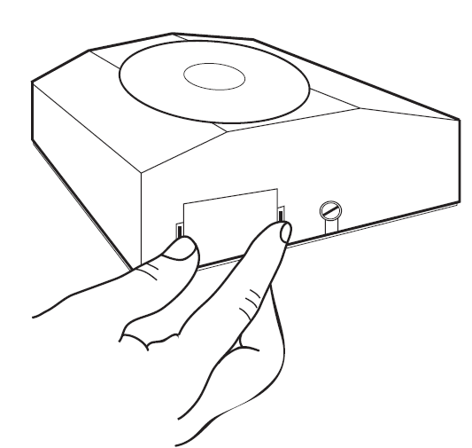
Remove the battery compartment by pinching the tabs and withdrawing downwards. Replace the spent batteries with 2 x AA 1.5V alkaline batteries ensuring correct orientation. Replace the battery compartment by pressing fully home.
Proper Battery Recycling
Electronic devices and batteries, rechargeable or not, should not be disposed of into ordinary household waste. Instead, they must be recycled properly to protect the environment and cut down the waste of precious resources. Your local waste management authority can supply details concerning the proper disposal of batteries. In compliance with the EU Directive 2006/66/EC, the button cell battery located on the printed circuit board inside this product, can be removed at the end of product life, by professional personnel only.
Location
Cylinder Thermostat
The transmitter should be located in a convenient position for the end user, close to the domestic hot water cylinder being controlled.
Signal Strength
Before fixing the Digistat+C RF to the wall it is recommended to first check the signal strength from that location. To do this, remove the batteries. Press and hold the ‘set’ button whilst refitting the batteries, keep the ‘set’ button held and after a few seconds the display will show ‘rF which indicates that the Digistat+CRF is continuously sending an OFF signal to the SCR (receiver). Leave the Digistat+C RF in position and return to view the SCR. If the red LED is continuously flashing. this indicates a good signal If the red LED is not flashing, this indicates a poor signal and you need to reposition the Digistat+CRF until the red LED is flashing When the signal strength has been confirmed remove the batteries to cancel the test and follow the installation instructions.
Before Installation
If you do not have the knowledge to install the thermostat safely then you must arrange for a competent electrician to install it for you. Wiring must conform to the current EE wiring regulations. Prior to commencing the installation, you must ensure the mains supply is switched off.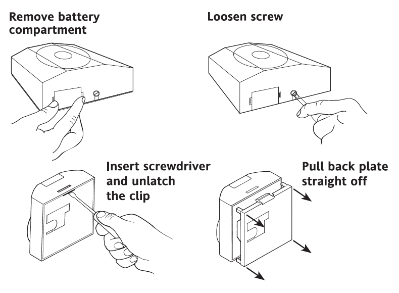
To wire the external sensor, snap out the cable entry strip on the bottom right edge of the thermostat cover.
WIRING
Cylinder Thermostat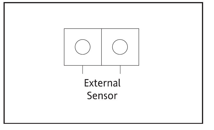
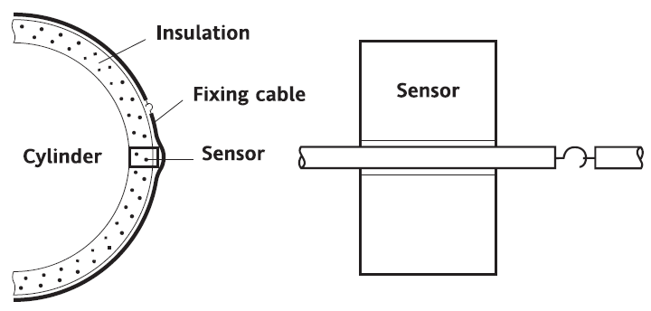
Cylinder Thermostat sensor
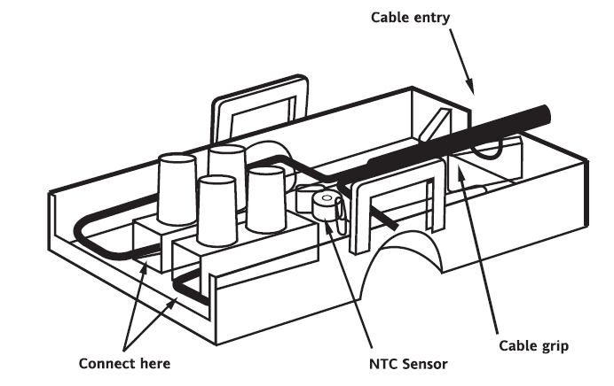
Unclip the housing to show the terminal block. First, connect a 2-core cable to the Digistat+C RF transmitter, and cut to the required length to reach the sensor position. Connect to the sensor in the position shown and fold wires back through the cable grip 8& out through the cable entry. re-assemble the housing.
 Clip the spacer provided onto the sensor housing
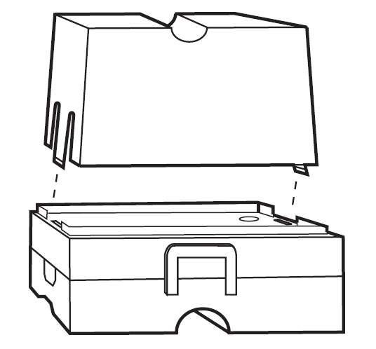
The sensor should be installed approximately one-third of the way up the hot water cylinder. With pre-insulated cylinders, mark the position and size, and remove just enough insulation to allow the sensor to fit against the metal of the cylinder in the recess formed.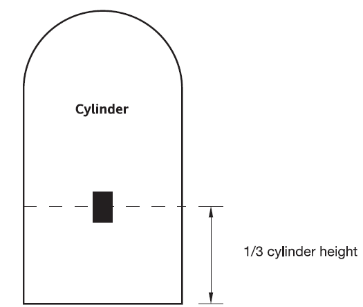
The plastic covered spring fixing cable should be cut to a unstretched length of approximately 60-75mm 21-3″) less than the circumference of the cylinder and the hook and eyelet should be screwed into the ends. Stretch the cable round the cylinder, over the insulation, and position it in the groove across the front of the sensor housing. Engage the hook and eyelet.
FAULT DIAGNOSIS
If the display shows E2, the following faults could have occurred
- The external temperature sensor has failed.
- Ambient temperature is outside the product operating temperature range
- External sensor has been wired incorrectly

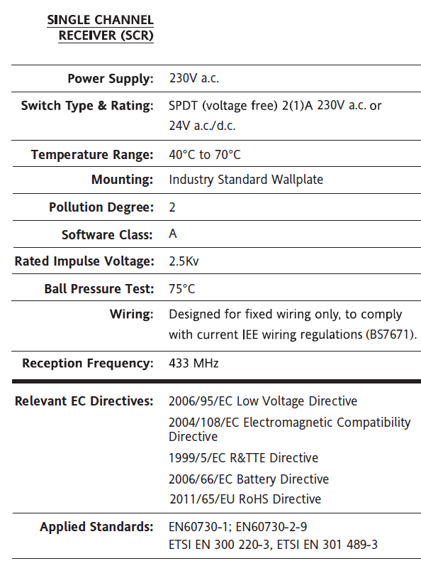
TECHNICAL DATA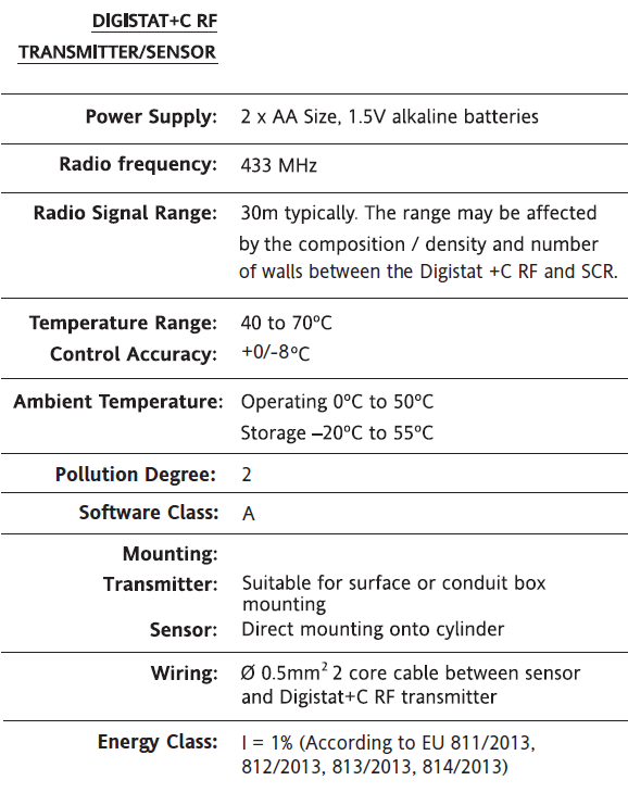
OTHER MANUALS:
Drayton Digistat +CRF 13616 Cylinder Thermostat Installation Guide
Drayton Digistat +CRF 13616 Cylinder Thermostat Product Specifications Guide

Leave a Reply