
Crestron HZ-THSTAT Wireless Programmable Thermostat
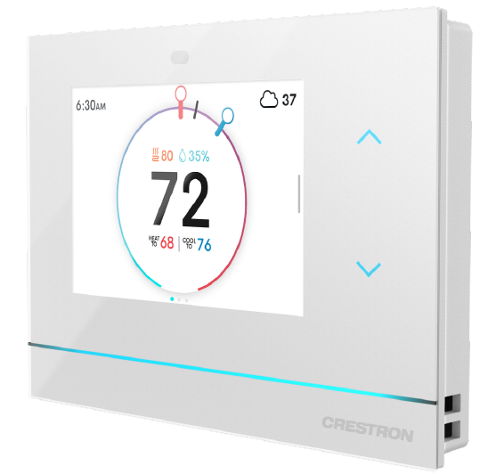
Horizon® Wireless Thermostat
The Crestron® HZ-THSTAT is a versatile, wall-mounted heating and cooling thermostat with integrated humidistat capable of controlling two stage heat/cool systems, two stage heat pump systems with two auxiliary heat stages, floor warming systems, and humidity systems. A Wi-Fi® thermostat, the HZ-THSTAT delivers enhanced functionality when combined with a complete Crestron automation system. When the HZ-THSTAT is paired with the HZA-CONV-THSTAT-2WIRE Common Wire Adapter accessory (sold separately), the thermostat can be used in installations without a common wire. The HZ-THSTAT has local temperature and humidity sensors and accommodates up to four remote temperature sensors (CHV-RTS, CHV-RSS, CHVI-RTS-1G-N-W, and CHVI-RTS-1G-SM-W, sold separately) and up to two remote temperature/humidity sensors (CHV-RTHS, sold separately) for optimized performance and flexibility. The HZ-THSTAT is also compatible with 10k thermistors.
In the Box
- 1 HZ-THSTAT, Horizon® Wireless Thermostat Additional Items
- 2 Anchor, Wall, Plastic, #6 x 1-1/4 in. (2043585)
- 1 Foam Insulation (2057585)
- 1 Plate, Mounting with Terminal Block (4530666)
- 2 Screw, 6-32 x 3/4 in., Flat Head, Phillips (2055126)
- 1 Template, Cutout (4531679)
- 2 Washer, Flat, Steel, #6 0.156 in. ID, 0.375 in. OD, 0.050 in. THK (2041707)
Install the Thermostat
NOTE: Installers should have a strong working knowledge of HVAC systems. The thermostat can be mounted directly to drywall, a low voltage mounting bracket (not included), or to an electrical box (not included) for new or old work applications.
Determine the Mounting Location
Install the thermostat away from direct sunlight, drafts, doorways, skylights, and windows. Also, make sure that the thermostat is conveniently located for control access and setup.
Follow the mounting requirements below:
- Mount 60 in. (~1.6 m) above the finished floor; this is an HVAC industry standard.
- On each side of the thermostat, allow at least 12 in. of lateral clearance to any wall features, such as corners or molding.
- Do not mount on an exterior wall. A cutout template is included and a mounting depth of 1.50 in. (38 mm) is required.
Equipment Required
The following tools and hardware are required for mounting the thermostat.
New Electrical Box or Low Voltage Mounting Bracket
Equipment included:
- Mounting screws
- Washers (not needed for low voltage mounting bracket)
Equipment not included
- Electrical box or low voltage mounting bracket
- Utility knife
- Level
- Stud finder
- Phillips screwdriver
Existing Electrical Box or Low Voltage Mounting Bracket
Equipment included:
- Mounting screws
- Washers (not needed for low voltage mounting bracket)
Equipment not included:
Phillips screwdriver
Drywall
NOTE: A low-voltage mounting bracket is recommended for retrofit drywall installations.
Equipment included:
- Mounting screws
- Cutout template
- Drywall anchors
Equipment not included:
- Utility knife
- Level
- Stud finder
- Phillips screwdriver
Mount the HZ-THSTAT
When mounting directly to drywall, use the included cutout template, a level (not included), and a utility knife (not included) to cut the mounting hole in the drywall
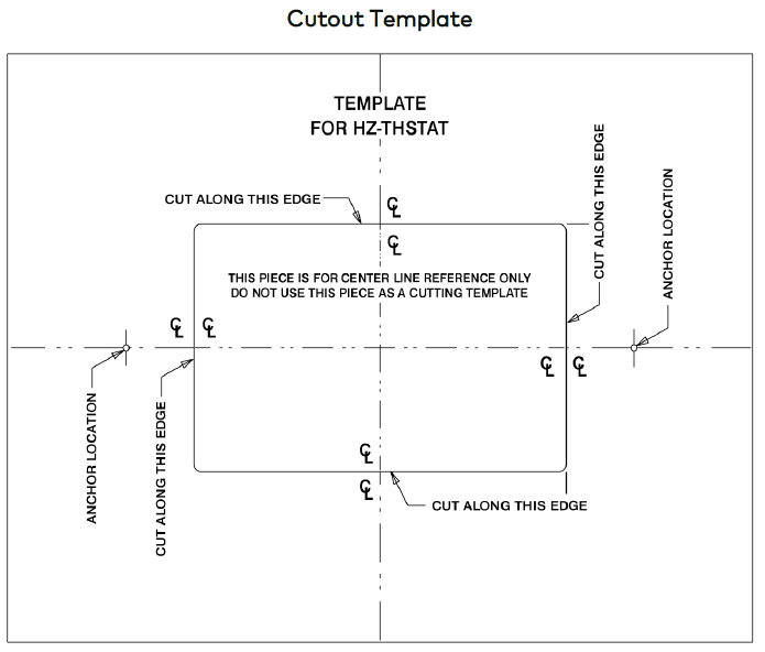
Cutout Template
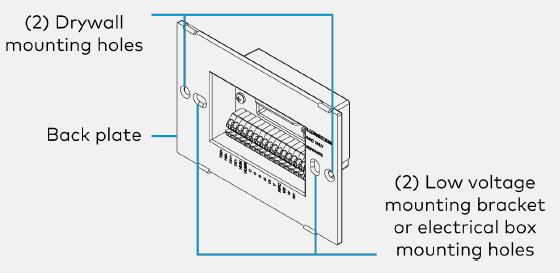
NOTE: For drywall installations, use the included drywall anchors. Make sure to use the outer screw holes on the back plate. For electrical box and low voltage mounting bracket (not included) installations, use the inner screw holes on the back plate.
Mount to an Electrical Box or Low Voltage Mounting Bracket
For applications with an existing electrical box or low-voltage mounting bracket:
- Turn the HVAC system power off.
- If there is an existing thermostat, take a picture or label the existing wire configuration before removing the old thermostat.
- Skip to step 7 in the following procedure.
Mount the thermostat to an electrical box or low-voltage mounting bracket:
NOTE: Use a stud finder to avoid any studs behind the wall.
- Turn the HVAC system power off.
- Level the box or bracket and draw a cutout template for the appropriate size. For an electrical box, trace the outside of the box For the low voltage mounting bracket, trace the inside of the bracket or use the corner holes for markings.
- Use a utility knife to cut around the outline of the drawn template.
- Keep retracing the outline cutting deeper until penetrating the back paper of the drywall. Clear away the excess drywall.
NOTE: Identify the wall type as Insulated (packed with insulation) or Non-Insulated (hollow). Assigning the wall type is necessary for the Installer Settings configuration. - Push the box or bracket through the mounting hole.
- Tighten the retaining screws until the box or bracket is held firmly in place.
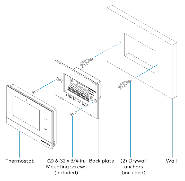
- Pull the wires through the thermostat backplate, and push the backplate into the box or bracket.
- Using the mounting screws (included), screw the backplate to the box or bracket. Do not over-tighten.
NOTE: Use the included washers to prevent overtightening when installing to a new work electrical box. - Wire the backplate. Refer to the Connect the Device section.
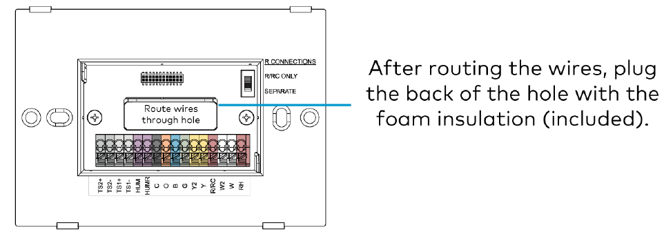
- Plug the wire hole on the back of the thermostat with the included foam insulation. Refer to the Wiring Diagrams section.
- Attach the thermostat to the backplate.

Mount to Drywall
For retrofit applications replacing an existing thermostat, turn the HVAC system power off and take a picture or label the current wire configuration before dismantling the current thermostat.
NOTES: When replacing a thermostat that was mounted to drywall with anchors, consider the following options: l move the installation up or down 1 in. from the existing position to avoid interference between the new and old anchor positions or
- use a low voltage mounting bracket (not included) Mount the thermostat to drywall:
NOTE: Use a stud finder to avoid any studs behind the wall. - Turn the HVAC system power off.
- Cut out the center rectangle of the included cutout template.
- Level the cutout template against the mounting surface, and trace the inside rectangle.
- Mark the anchor locations.
- Use a utility knife to cut around the outline of the drawn template.
- Keep retracing the outline cutting deeper until penetrating the back paper of the drywall. Clear away the excess drywall.
NOTE: Identify the wall type as Insulated (packed with insulation) or Non-Insulated (hollow). Assigning the wall type is necessary for the Installer Settings configuration. - Screw in both self-tapping anchors (included) through the locations marked earlier.
- Pull the wires through the thermostat backplate, and push the backplate into the mounting hole. Using the mounting screws (included), screw the backplate to the anchors. Do not over tighten.
- Wire the backplate. Refer to the Connect the Device section.
- Plug the wire hole on the back of the thermostat with the included foam insulation. Refer to the Wiring Diagrams section.
- Attach the thermostat to the backplate
Connect the Device
Make the necessary connections as called out in the illustrations. A miniature flathead screwdriver (not supplied) may be required to attach thinner gauged wires to the backplate terminals. Press the terminal release with the flathead screwdriver while inserting the wires. Apply power after all connections have been made.
CAUTION: To avoid a possible short circuit, ensure the excess wire is pushed back through the hole in the backplate.
NOTES:
- This device is rated for 24VAC operation.
- For installations without a common wire, the HZA-CONV-THSTAT-2WIRE 2-wire power adapter (sold separately) may be used. Refer to the Connect the Device section for wiring details.
R CONNECTIONS Switch
The thermostat pulls power from both the R terminal and the C terminal. The position of the R Connections switch decides which R connection is routed to the heat calls (W/W2).
NOTES:
- When using the HZA-CONV-THSTAT-2WIRE, always make connections to the R/RC terminals and set the switch to R/RC ONLY.
- When power is not available from the HVAC system, a separate 24VAC transformer can be connected between the RH and C terminals to provide power to the thermostat. Set the R
- Connections switch to R/RC ONLY to ensure all calls use the R/RC reference.
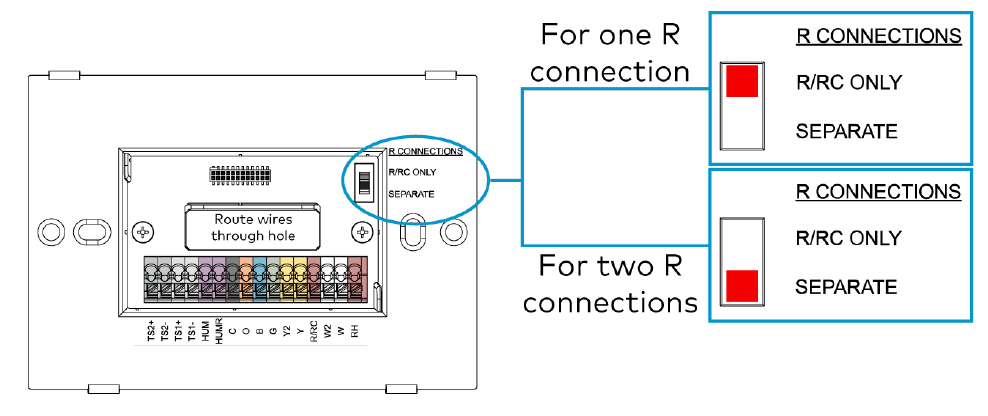
Before attaching the thermostat, note the position of the R CONNECTIONS switch.
- For one R connection (24VAC reference), wire to the R/RC terminal and set the switch to R/RC ONLY.
- For two R connections (24VAC reference), wire to the R/RC and RH terminals and set the switch to SEPARATE.
Thermistor Curve
The thermostat is compatible with Crestron remote sensors and 10K thermistors. Refer to the table for information on the supported thermistor temperature curve.
| Temperature | k-ohm |
| -30°F (-34.4°C) | 185.42 |
| 0°F (-17.8°C) | 81.72 |
| 40°F (4.4°C) | 26.11 |
| 80°F (26.7°C) | 9.37 |
| 90°F (32.2°C) | 7.41 |
| 110°F (37.8°C) | 4.75 |
| 120°F (48.9°C) | 3.98 |
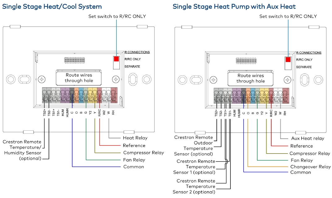
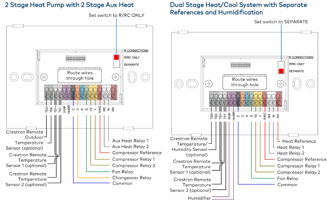
Wiring Diagrams
The following diagrams are a sampling of possible wiring solutions and do not represent all wiring options.
- Single Stage Heat-Only System without Common Wire
- Single Stage Heat/Cool System without Common Wire
- Single Stage Heat/Cool System
- Single Stage Heat Pump with Aux Heat
- Dual Stage Heat/Cool System with Separate References and Humidification
- Wiring a Local Power Source
After wiring the thermostat, plug the wire hole on the back of the thermostat with the included foam insulation. The insulation prevents drafts and ensures accurate temperature readings.
NOTE: For Radiant Floor, if the Radiant type is Floor Warming, Space Heating, or Floor Warm/Space Heat, always connect the radiant floor call wire to W2. Space Heating or Floor Warm/Space Heat will always use the radiant floor as the first stage of heat.
Horizon® Wireless Thermostat

Single Stage Heat/Cool System
2-Stage Heat Pump with 2-Stage Aux Heat
Wiring a Local Power Source
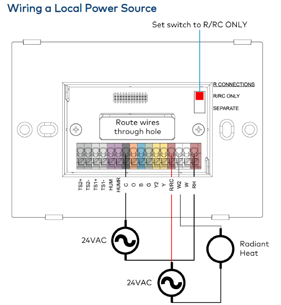
NOTE: If the HVAC system only requires one reference, a 24VAC power source can be used to power the device locally.
Firmware Upgrade
Before using the thermostat, ensure it is using the latest firmware. Check for the latest firmware at www.crestron.com/firmware. Load the firmware onto the thermostat using Crestron Toolbox™ software or a web-based user interface.
Configure the Device
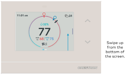
To set up the thermostat:
- Swipe up from the bottom of the screen.
- Tap the Gear icon to open the Settings
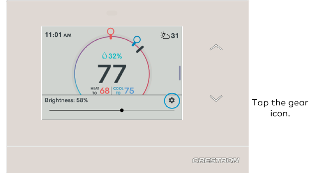
- From Settings, access Installer Mode by using the following tap sequence on the Up and Down capacitive button: Up, Up, Down, Down. Installer Mode opens.

For detailed setup information, refer to the HZ-THSTAT Product Manual (Doc. 8622).
Visit the Product Page
Scan the QR code to visit the product page.
HZ-THSTAT-W
www.crestron.com/model/6511011
HZ-THSTAT-B

www.crestron.com/model/6511010
HZ-THSTAT-A

www.crestron.com/model/6511012
Additional Information
Original Instructions
The U.S. English version of this document is the original instructions. All other languages are a translation of the original instructions.
Regulatory Model: M201911001
Crestron product development software is licensed to Crestron dealers and Crestron Service Providers (CSPs) under a limited nonexclusive, nontransferable Software Development Tools License Agreement. Crestron product operating system software is licensed to Crestron dealers, CSPs, and end-users under a separate End-User License Agreement. Both of these Agreements can be found on the Crestron website at www.crestron.com/legal/software_license_agreement. The product warranty can be found at www.crestron.com/warranty.
The specific patents that cover Crestron products are listed at www.crestron.com/legal/patents. Certain Crestron products contain open-source software. For specific information, visit
www.crestron.com/opensource. Crestron, the Crestron logo, and Horizon are either trademarks or registered trademarks of Crestron Electronics, Inc. in the United States and/or other countries. Wi-Fi is either a trademark or a registered trademark of Wi-Fi Alliance in the United States and/or other countries. Other trademarks, registered trademarks, and trade names may be used in this document to refer to either the entities claiming the marks and names or their products. Crestron disclaims any proprietary interest in the marks and names of others. Crestron is not responsible for errors in typography or photography. ©2021 Crestron Electronics, Inc. Doc ID 8620B 11/23/21
REFERENCE:
DOWNLOAD MANUALS:
Crestron HZ-THSTAT Wireless Programmable Thermostat Product Manuals
![]()
Crestron HZ-THSTAT Wireless Programmable Thermostat Product Manuals
Leave a Reply