
Crestron CHV-TSTAT HEATING OR COOLING Thermostat
- Wall mount heat/cool thermostat for one- and two-stage control of forced air, radiant, and heat pump HVAC systems
- Multiple Crestron® thermostats may be networked via Cresnet®
- Supports remote humidity sensors and outdoor temperature sensors
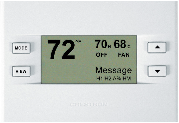
- Backlit LCD display
- Front panel buttons for setup, configuring, and temperature and humidity adjustments[1]
- Available in white, black, or almond finish
The CHV-TSTAT is a versatile heating and cooling thermostat for one- and two-stage control of forced air, radiant, and heat pump HVAC systems. Relative humidity capability can be added through an external remote humidity sensor (sold separately). Although functional as a standalone thermostat, the CHV-TSTAT delivers greatly enhanced functionality as part of a complete home automation system from Crestron®. Available in white, black, or almond, the stylish wall mount design is a complement to any décor.
The large backlit LCD display, navigable using four simple pushbuttons, provides easy access to indoor and outdoor temperature and humidity readings, setpoint adjustments, system mode and fan status indicators, and setup menus. Climate control features include separate heating, cooling, and humidity setpoints with optional automatic changeover between heating and cooling modes. Adjustable anticipators prevent overshooting the set temperature, and continuous fan operation can be selected when needed for increased circulation.
Automation System Integration
Multiple Crestron thermostats may be networked via Cresnet® to any 3-Series ® control system, including the DIN-AP3, enabling global temperature and humidity adjustment from any thermostat. Automation functions such as lighting, motorized blinds, or lawn sprinklers can be accessed through two custom remote function pages and customized text messages can be sent to the LCD display to provide maintenance reminders and other alerts. Its connection to the control system also allows for full control and scheduling of the CHV-TSTAT from touch screens and computers throughout the home and supports extensive flexibility for integration with other devices and systems. In the event that communication with the control system is disrupted for any reason, the CHV-TSTAT will remain operable to control the HVAC system.
Remote Sensors
Optional remote temperature and humidity sensors can be connected to the CHV-TSTAT for enhanced flexibility and optimized performance. Climate can be regulated according to an average of multiple sensors, or the built-in sensors can be disabled entirely to allow the CHV-TSTAT to be installed out of view. Outdoor climate can also be monitored, enabling outdoor low-temperature compensation to prevent condensation on windows during cold weather. The CHV-TSTAT accepts up to four remote temperature sensors, two remote temp/humidity sensors, or a combination of one temp/ humidity and two temperature sensors.
SPECIFICATIONS
Measurement Range
- Indoor Temperature: 0° to 110°F (-18° to 43°C)
- Outdoor Temperature: -40º to 170ºF (-40º to 77ºC)[1]
- Humidity: 0% to 100% RH[1]
Temperature Tolerance
- Over Full Range: ±1ºF (±0.5ºC)
- At Room Temperatures: ±1ºF (+0.1/-0.4ºC)
Setpoint Range
- Auto Setpoint: 38° to 99°F (3° to 37°C)
- Heat only Setpoint: 38° to 89°F (3° to 32°C)
- Cool only Setpoint: 59° to 99°F (15° to 37°C), or 38° to 99°F (3° to 37°C)
extended cool mode enabled
- Humidity Setpoint: 5% to 70% RH[1]
Relay Rating
- 1 Amp @ 40 Volts DC or 24 Volts AC (nominal)
Power Requirements
- 24V: 2 Watts (0.083 Amps) @ 24 Volts AC, supplied by heating or cooling system
- Cresnet Power Usage: <1 Watts (<0.05 Amps @ 24 Volts DC), required for Cresnet® communication only
Buttons
- MODE: Accesses user controls – system mode, fan mode, humidifier[1], Crestron® system, and global update
- VIEW: Accesses humidity reading[1], outdoor temperature reading[1], system messages, and remote functions
- UP: Selects user modes and increments selection in setup modes
- DOWN: Selects user modes and decrements selection in setup modes
Display
- Type: Transflective LCD, backlit
- Size: 2.75 in (6.99 cm)
- Resolution: 128 x 64
- Viewing Angle: ±50° horizontal (@0° vertical), ±50° vertical (@0°
- horizontal); Displays current indoor temperature and relative humidity[1], outdoor temperature and relative humidity[1], setpoints, activity, function, Cresnet system information, internal relay status, setup menus, and control system messages.
Connectors
- HVAC: (2) 9-position terminal blocks comprising the following: Power Connections (Required):
- 24 (C): 24V AC common terminal supplies remote 24V AC power to thermostat;
- 24 (R): 24V AC reference terminal – Can be connected to RH or RC by P4 jumper setting, or tied directly to a power source
HVAC Control Connections (System Dependent):
- HUM: Energized to RHU during humidity call;
- RHU: Reference for humidifier;
- RH: Reference Heat – Used for calls to the heating system;
- RC: Reference Cool – Used for calls to cooling system;
- G: Fan – Energized to RC during the call for fan;
- Y/Y1: Compressor (stage one) – Energized to RC when the compressor (or first stage) is run;
- Y2: Compressor (stage two) – Energized to RC on two-stage systems on call for the second stage;
- O: Changeover control – Energized to RC during cooling modes;
- B: Energized to RC during non-cooling modes;
- W/W1: Heat (single stage)/heat (stage one) – Energized to RH during a call for heat in heat/cool systems or aux heat in heat pump systems;
- W2: Heat (stage two) – Energized to RH during a call for second-stage heat in heat/cool systems
Remote Sensing Connections (Optional)
- RSR: Remote Sensor Returns – Common sensor terminal;
- RS1: Remote Sensor terminal – Connect the sensor from RS1 to RSR;
- RS2: Remote Sensor terminal – Connect the sensor from RS2 to RSR
- NETWORK: (1) 4-position terminal block;
The Cresnet slave port connects to the Cresnet control network Enclosure
Plastic, surface-mountable to the front of a horizontally oriented 1-gang electrical box
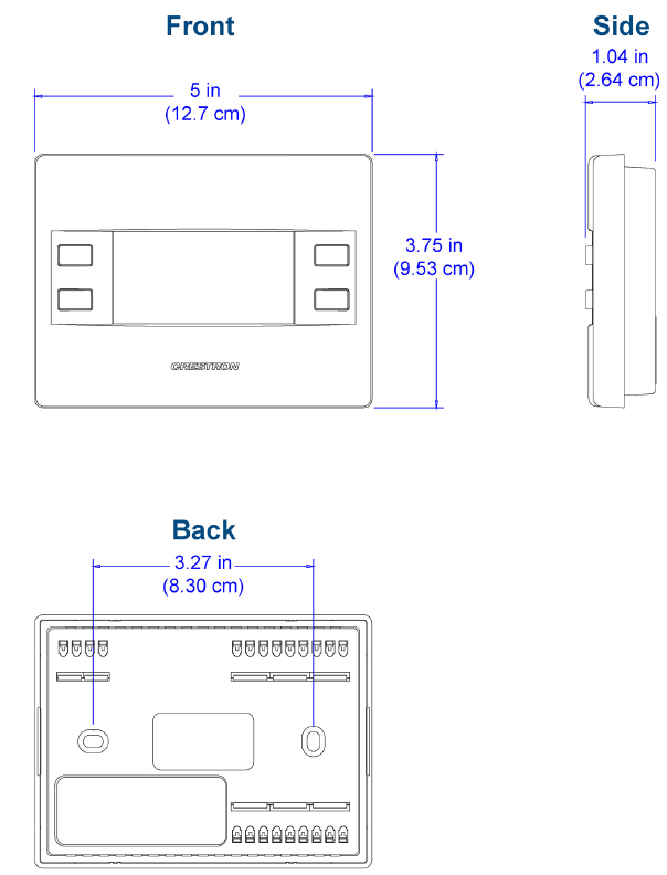
Dimensions
- Height: 3.75 in (96 mm)
- Width: 5.00 in (127 mm)
- Depth: 1.04 in (27 mm)
Weight
- 5.80 oz (165 g)
MODELS & ACCESSORIES
Available Models
- CHV-TSTATA: Heating and Cooling Thermostat, Almond Faceplate
- CHV-TSTATB: Heating and Cooling Thermostat, Black Faceplate
- CHV-TSTATW: Heating and Cooling Thermostat, White Faceplate
Available Accessories
- CHV-RSS: Remote Slab Sensor and Outdoor Temperature Sensor
- CHV-RTHS: Remote Temperature and Humidity Sensor
- CHV-RTS: Remote Temperature Sensor
- CRESNET-HP-NP-TL-SP1000: Cresnet® “High-Power” Control Cable, nonplenum, teal, 1000 ft spool
- CRESNET-HP-NP-TL-SP500: Cresnet® “High-Power” Control Cable, nonplenum, teal, 500 ft spool
- CRESNET-NP-BK-B500: Cresnet® Control Cable, non-plenum, black, 500 ft box
- CRESNET-NP-OR-B500: Cresnet® Control Cable, non-plenum, orange, 500 ft box
- CRESNET-NP-TL-B250: Cresnet® Control Cable, non-plenum, teal, 250 ft box
- CRESNET-NP-TL-B500: Cresnet® Control Cable, non-plenum, teal, 500 ft box
- CRESNET-NP-TL-SP1000: Cresnet® Control Cable, non-plenum, teal, 1000 ft spool
- CRESNET-NP-TL-SP500: Cresnet® Control Cable, non-plenum, teal, 500 ft spool
- CRESNET-NP-YL-B500: Cresnet® Control Cable, non-plenum, yellow, 500 ft box
- CRESNET-P-BK-SP500: Cresnet® Control Cable, plenum, black, 500 ft spool
- CRESNET-P-OR-SP500: Cresnet® Control Cable, plenum, orange, 500 ft spool
- CRESNET-P-TL-SP1000: Cresnet® Control Cable, plenum, teal, 1000 ft spool
- CRESNET-P-TL-SP500: Cresnet® Control Cable, plenum, teal, 500 ft spool
- CRESNET-P-YL-SP500: Cresnet® Control Cable, plenum, yellow, 500 ft spool
Notes:
Humidity sensing and outdoor temperature/humidity sensing require additional remote sensors, sold separately. See “Available Accessories” for model names. This product may be purchased from an authorized Crestron dealer. To find a dealer, please contact the Crestron sales representative for your area. A list of sales representatives is available online at www.crestron.com/salesreps or by calling 800-237-2041. The specific patents that cover Crestron products are listed online at: patents.crestron.com.Crestron, the Crestron Logo, 3-Series, and Cresnet are either trademarks or registered trademarks of Crestron Electronics, Inc. in the United States and/or other countries. Other trademarks, registered trademarks, and trade names may be used in this document to refer to either the entities claiming the marks and names or their products. Crestron disclaims any proprietary interest in the marks and names of others. Crestron is not responsible for errors in typography or photography. Specifications are subject to change without notice. ©2014 Crestron Electronics, Inc.
Crestron Electronics, Inc. 15 Volvo Drive
Rockleigh, NJ 07647
Tel: 800.237.2041 / 201.767.3400
Fax: 201.767.1903
www.crestron.com All brand names, product names, and trademarks are the property of their respective owners. ©2014 Crestron Electronics, Inc.
Specifications are subject to change without notice. Revised 05/30/14
Reference
Download Manual:
Crestron CHV-TSTAT HEATING OR COOLING Thermostat Product Specification Guide
![]()
Crestron CHV-TSTAT HEATING OR COOLING Thermostat Thermostat Product Specification Guide
Leave a Reply