Crestron CHV-THSTAT Wireless Programmable Thermostat
Quick Installation Reference
- Select a suitable location and run the connecting wires from the heating/cooling system and the Cresnet system. Refer to page 5 for a description of the thermostat connectors.
Refer to page 7 for Network wiring details.
Use the appropriate wiring diagram:- Separately Powered Two Wire Heat
(Powered by an Independent Transformer) (Refer to page 13) - Single Stage Heat Only (Refer to page 13)
- Single Stage Heat with Fan Control (Refer to page 14)
- Single Stage Cool Only (Refer to page 14)
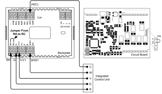
- Single Stage Heat/Cool with Integrated Control Unit (Refer to page 15)
- Single Stage Heat/Cool with Separate Systems (Refer to page 16)
- Single Stage Heat Pump (Refer to page 17)
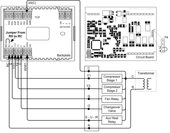
- Two Stage Heat Pump (Refer to page 18)
- Slab 1, Slab 2, and Slab 3 Systems (Floor Warming and/or Space Heating) (Refer to page 19)
- Slab 4A Two Stage Heat/Single Stage Cool Systems,
Slab 5A Floor Warming with Single Stage Space Heat/Cool (Refer to page 20) - Slab 4B Two Stage Heat/Single Stage Cool System,
Slab 5B Single Stage Heat/Cool with Floor Warming (Refer to page 21) - General Humidifier Connections (Refer to page 22)
- Separately Powered Two Wire Heat
- Separate the thermostat from the backplate to expose the connections and mounting holes.
- Mount the thermostat backplate (60 inches above the finished floor) directly to the wall with wall anchors (not provided) and screws (not provided) or to a single-gang box (not provided) mounted horizontally, and connect the wiring. Refer to page 23 for detailed mounting instructions and page 8 for detailed connector information. If using a five-sided box, fill with insulation material to minimize wall air ingress.
- Install the thermostat on the backplate (Refer to page 23).
- Setup the thermostat (Refer to page 25).
- Heat/Cool Radiant and Forced Air Systems Setup on page 28.
- Heat Pump Systems on page 31.
- Slab Systems begin on page 34.
- Configure the thermostat (Refer to “Operating the Thermostat” on page 55).
Introduction
Functions and Features
The CHV-TSTAT and CHV-THSTAT series are wall-mounted universal thermostats that can be part of a Crestron Home® total control system. The thermostats are capable of controlling one or two-stage heating and cooling systems. Each thermostat is available in three colors: almond, black and white. The suffix ‘A’, ‘B’, and ‘W’, respectively denotes color, e.g., CHV-TSTATB is a black unit. For simplicity within this guide, color suffix is omitted and the designations CHV-TSTAT and CHV-THSTAT are used except where noted.
Functional Summary
- User adjustable temperature and/or humidity control of one and two-stage heating and cooling systems
- Supports seven slab system configurations
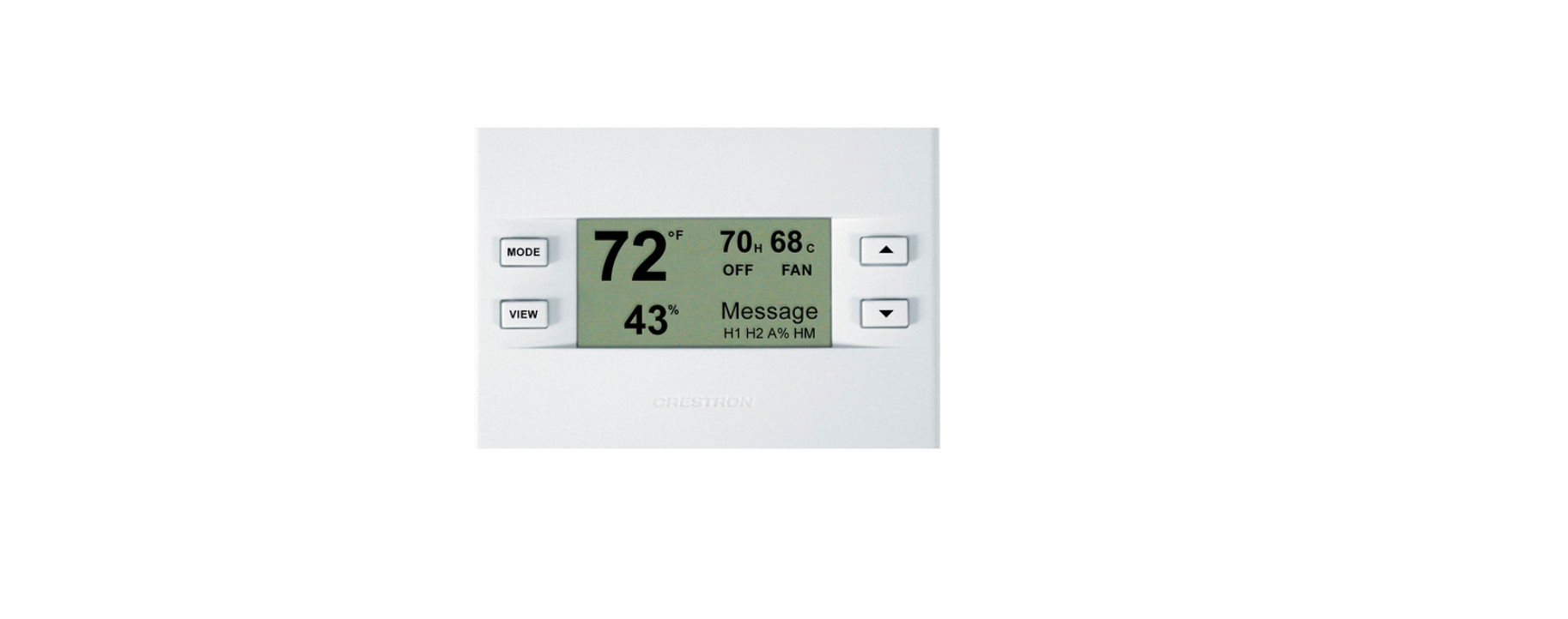
- 128 x 64 transflective 2.75 inch (6.99 cm) LCD display
- Fahrenheit or Celsius indication
- Four-front panel buttons for setup, configuring and temperature/humidity adjustments
- Back light (with each button press) for night viewing
- Supports up to four remote temperature and/or temperature/humidity sensors.
- Operates as a stand-alone device or in a Cresnet® system
- Extended functionality as a Cresnet device for lighting control, alarms, etc.
The CHV-TSTAT provides temperature control, while the CHV-THSTAT provides temperature and humidity control. Temperature and humidity information is provided through a transflective LCD display. Four front panel buttons and the LCD display provide temperature and/or humidity indication and control, current system status, and current fan mode. The LCD also provides status indicators denoting when heat, cool, humidity or fan outputs are energized; a message indicator, so users know when a message is waiting to be read; a net indicator to denote when the network is active and a hold indicator that identifies when the thermostat is overriding the Cresnet temperature set point commands.
Firmware Versions
The new features, and consequent changes to the SIMPL Windows symbol programming, for firmware version 2.0 and later make it incompatible for use with X-generation control processors. In addition, upgrading to release 2.0 and later from a previous release will require a complete re-programming of the thermostat.
Remote Sensors
Firmware version 2.0 and later supports up to four optional remote sensors, two for each input channel: temperature only (CHV-RTS), temperature/humidity (CHV-RTHS), and slab sensor (CHV-RSS) for both thermostats. Information from two sensors that share an input channel is averaged together in the temperature/humidity calculations.
Outdoor conditions, -40º to 170º F (-40º to 77º C), can be imported from the CHV-RSS slab sensor.
For additional information about the sensors, refer to the latest revision of the CHV-RTS & CHV-RTHS Installation Guide (Doc. 8189), and the CHV-RSS Installation Guide (Doc.6229) which are available from the Crestron website (www.crestron.com).
NOTE: The CHV-TSTAT and CHV-THSTAT allow the user to set a temperature that the heating and/or cooling system maintains. This is called the “Set Point”. Refer to “Operating the Thermostat” on page 55 for more information.
Heating and Cooling Systems
The CHV-TSTAT can control the following heating and cooling systems:
- One stage heat
- One stage heat, one stage cool
- One stage heat, one stage cool (heat pump with auxiliary heat)
- Two stage heat
- Two stage heat, one stage cool
- One stage heat, two stage cool
- Two stage heat, two stage cool
- Two stage heat, two stage cool (heat pump with auxiliary heat)
- Wide range cool option suitable for wine cellars or other chilling processes*
- Slab settings for heating and floor warming systems*
- Firmware version 2.0 or higher.
NOTE: Two Stage Heating – Unlike traditional furnaces that turn on and run at full capacity with each demand for heating, two-stage heat operates like two separate furnaces to maintain more consistent comfort in your home. The unit starts out running in its first stage, and operates at a fraction of its heating capacity. This reduced capacity is sufficient to warm your home on mild winter days. But when the temperature outside goes very low, the furnace adjusts to full capacity (second stage) to meet the demand for heat within the home.
Two Stage Cooling – In warm weather, the first stage of the cooling equipment operates at a fraction of the total cooling capacity. On very hot days, the second stage of the cooling equipment energizes, and the cooling system operates at full capacity.
Specifications
The following table provides a summary of specifications for the CHV-TSTAT and CHV-THSTAT.
CHV-TSTAT and CHV-THSTAT Specifications
| SPECIFICATION | DETAILS |
| Power Requirements | 2 Watts (24 VAC @ 83mA) Heating or Cooling System Supplied |
| Crestron power factor | <1 Watt (required for Cresnet communication only) |
| Default Network ID | 2A |
| Control System Update Files1,2 |
Version 3.080.CUZ or later |
| 2-Series Control System | |
| LCD Display | 128 x 64 Transflective 2.75 in (6.99 cm) |
| Screen Viewing Angles | Y Dir. (X=0º): +50º (from top) –50º (from bottom)
X Dir. (X=10º): +50º (from right) –50º (from left) |
| Humidity Measurement Range | 0 – 100% |
| Auto Setpoint Range (union of heat and cool setpoint ranges) | 38 –- 99°F (3 – 37°C) |
| Heat Only Setpoint Range | 38 –- 89°F (3 – 32°C) |
| Cool Only Setpoint Range | 59 –- 99°F (15 – 37°C) |
| Temperature Measurement Range | 0 – 110°F (-18 – 43°C) |
| Firmware Update Files3
CHV-TSTAT/CHV-THSTAT |
CHV-TxSTAT.v2.40.UPG or later |
| Dimensions and Weight | Height: 3.75 in (9.50 cm)
Width: 5.00 in (12.70 cm) Depth: 1.04 in (2.63 cm) Weight: 5.80 oz (165 g) |
Physical Description
Refer to the following illustrations. The CHV-TSTAT and CHV-THSTAT are in a plastic enclosure with four buttons and an LCD display on the front. The back of the unit has ventilation slots, and holes for mounting the unit and wiring. The ventilation slots must be unobstructed for airflow to the unit.
Physical View of CHV-TSTAT and CHV-THSTAT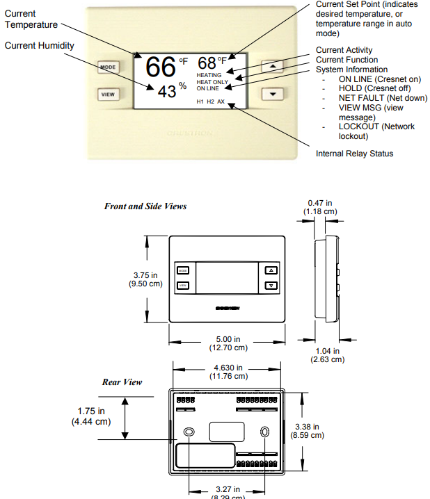
Connection View (Backplate, view from the front with cover removed)
Ports
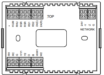
The CHV-TSTAT and CHV-THSTAT have four types of connections on the inside back plate (refer to graphic above).
NETWORK (Optional) – provides communication to the control system and Cresnet power to the CHV-TSTAT and CHV-THSTAT. If making network connections to Cresnet peripherals, refer to “Network Wiring” on.
Cresnet Connections (optional)
| PIN | DESCRIPTION |
| 24 | +24VDC |
| Y | Cresnet Data |
| Z | Cresnet Data |
| G | Ground |
Remote Sensing Connections (optional)
| PIN | DESCRIPTION |
| RSR | Remote Sensor Returns – Common sensor terminal |
| RS1 | Remote Sensor terminal – Connect the sensor from RS1 to RSR |
| RS2 | Remote Sensor terminal – Connect the sensor from RS2 to RSR |
Power Connections (Required)
| PIN | DESCRIPTION (refer to “System Connections” on |
| 24 (C) | 24 VAC common terminal supplies remote 24 VAC power to thermostat |
| 24 (R) | 24 VAC reference terminal. Can be connected to RH or RC by P4 jumper setting, or tied directly to power source (refer to System Connections on page ) |
Control Connections (System Dependent)
| PIN | DESCRIPTION |
| HUM | Energized to RHU during humidity call |
| RHU | Reference for humidifier |
| RH | Reference Heat, used for calls to heating system |
| RC | Reference Cool, used for calls to cooling system |
| G | Fan, energized to RC during call for fan |
| Y/Y1 | Compressor (stage one), energized to RC when compressor (or first stage) is run |
| Y2 | Compressor (stage two), energized to RC on two-stage systems on call for second stage |
| O | Changeover control, energized to RC during cooling modes |
| B | Energized to RC during non-cooling modes |
| W/W1 | Heat (single stage)/heat (stage one) energized to RH during a call for heat in heat/cool systems or aux heat in heat pump systems |
| W2 | Heat (stage two), energized to RH during a call for second stage heat in heat/cool systems |
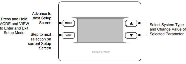
Buttons
There are four buttons used to setup and adjust the thermostat.
MODE – Access to the user controls (System Mode, Fan Mode, Humidifier, Crestron System, and Global Update)
VIEW – Access to Humidity reading, Outdoor Temperature reading, and System Messages.
NOTE: When MODE and VIEW are pressed together and held for five seconds, the thermostat enters the system setup mode (refer to “Thermostat Setup and Operation” on page 25).
UP ▲ – Selects user modes and increments selection in setup modes
DOWN ▼ – Selects user modes and decrements selection in setup modes
Industry Compliance
As of the date of manufacture, this unit has been tested and found to comply with specifications for CE marking and standards per EMC and Radio Communications Compliance Labeling (N11785).
NOTE: This device complies with part 15 of the FCC rules. Operation is subject to the following two conditions: (1) this device may not cause harmful interference, and (2) this device must accept any interference received, including interference that may cause undesired operation.
Setup
Network Wiring
NOTE: When installing network wiring, refer to the latest revision of the wiring diagram(s) appropriate for your specific system configuration, available from the Downloads | Product Manuals | Wiring Diagrams section of the Crestron website (www.crestron.com).
When calculating the wire gauge for a particular Cresnet run, the length of the run and the power factor of each network unit to be connected must be taken into consideration. If Cresnet units are to be daisy-chained on the run, the power factor of each unit to be daisy-chained must be added together to determine the power factor of the entire chain. If the unit is a home-run from a Crestron system power supply network port, the power factor of that unit is the power factor of the entire run. The length of the run in feet and the power factor of the run should be used in the following resistance equation to calculate the value on the right side of the equation.
Resistance Equation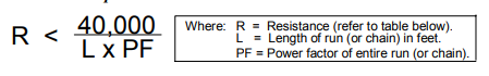
The required wire gauge should be chosen such that the resistance value is less than the value calculated in the resistance equation. Refer to the table below.
Wire Gauge Values
| RESISTANCE | WIRE GAUGE |
| 4 | 16 |
| 6 | 18 |
| 10 | 20 |
| 15 | 22 |
| 13 | Doubled CAT5 |
| 8.7 | Tripled CAT5 |
NOTE: All Cresnet wiring must consist of two twisted-pairs. One twisted pair is the +24V conductor and the GND conductor and the other twisted pair is the Y conductor and the Z conductor.For larger networks (i.e., greater than 28 network devices), it may be necessary to add a Cresnet Hub/Repeater to maintain signal quality throughout the network. Also, for networks with lengthy cable runs or varying types of network equipment, it may be desirable to add a hub/repeater after only 20 network devices.
System Connections
NOTE: Installers should have a strong working knowledge of HVAC systems.
Backplate – view from the front with the cover removed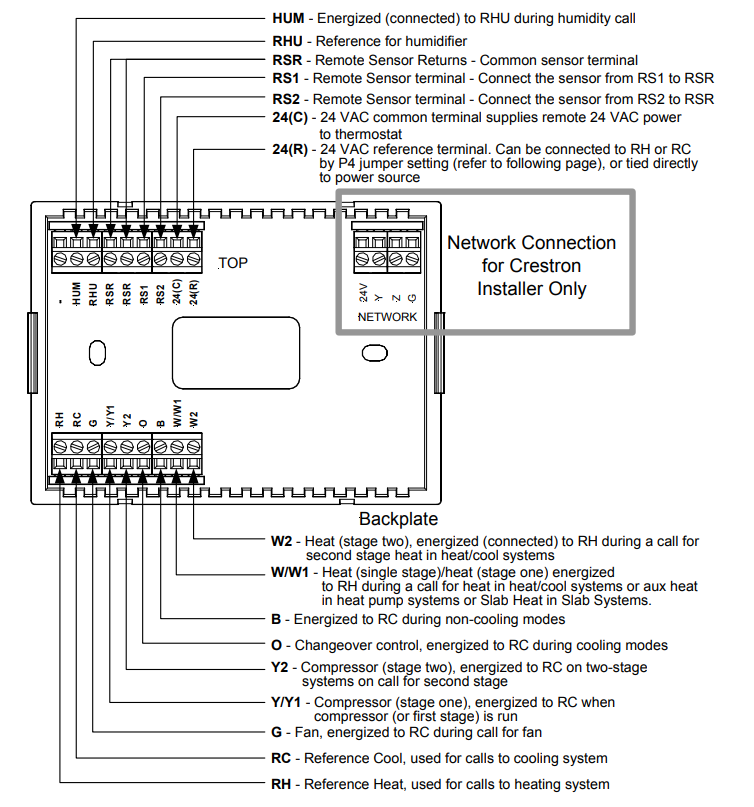
Identity Code
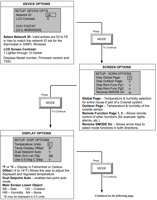
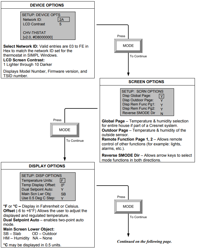
Every equipment and user interface within the network requires a unique identity code (Net ID). These codes are two-digit hexadecimal numbers from 03 to FE. The Net ID of each unit must match an ID code specified in the SIMPL Windows program. Refer to “Setting the Net ID in Device Settings” on page 61 for details of the SIMPL Windows procedure. The Net ID of the Thermostats has been factory set to 2A. The Net IDs of multiple thermostats in the same system must be unique. Net IDs are changed from a personal computer (PC) via the Crestron Viewport.
NOTE: The Crestron Viewport is available as a pull-down command from SIMPL Windows and VisionTools® Pro-e (Tools | Viewport) or as a standalone utility. The Viewport utility performs multiple system tasks, primarily via an RS-232 or TCP/IP connection between the control system and a PC. It is used to observe system processes, upload new operating systems and firmware, change system and network parameters, and communicate with network device consoles and touchpanels, among many other tasks. Viewport can function as a terminal emulator for generic file transfer. All of these functions are accessed through the commands and options in Viewport menus. Therefore, for its effectiveness as a support and diagnostic tool, the Crestron Viewport may be preferred over development tools when uploading programs and projects.
NOTE: For detailed information on establishing communication between the PC and control system, refer to “Communication Settings” in the Operations Guide of the control system. If communication cannot be established, refer to the
“Troubleshooting Communications” section in the respective Operations Guide for the control system.
- The NET ID can also be changed using the setup screens.
- Firmware version 2.40 and later supports Touch Settable ID.
There are two different methods—Method A or Method B—for setting the Net ID:
Method A (Cresnet address-settable ID), described as follows, applies to devices in a Cresnet system with a 2-Series control system and requires that a single unit be the only network device connected to the control system.
Method B (Touch Settable ID or TSID), which begins on page 10, applies to all TSID-ready devices in a Cresnet system with 2-Series control system upgrade file (CUZ) version 3.029 or later. TSID functionality makes it possible for the control system to recognize a network device via its serial number, which is stored in the device’s memory. This method does not require that any devices be disconnected from the network; Net IDs may be set with the entire Cresnet system intact. This method requires the use of the Crestron Viewport version 3.35 or later.
- Use the appropriate method to set the Net ID.
Method A (Cresnet address-settable ID)
- Ensure that the device requiring a Net ID change is the only unit connected to the control system.
- Open the Crestron Viewport.
- From the Viewport menu, select Functions | Set Network ID. The software checks the baud rate and then opens the “Set Network ID” window.
- In the “Set Network ID” window, select the device requiring a Net ID change from the Current Network Devices text window.
- Select the new Net ID for the device from the Choose the new network ID for the selected device (Hex): text box.
- Click Set ID to initiate the change. This will display the “ID command has been sent” window.
- In the “Command Complete” window, click OK.
- In t he Current Network Devices text window, verify the new Net ID code.
- In the “Set Network ID” window, click Close.
NOTE: The new Net ID code may also be verified by selecting Diagnostic | Report Network Devices in the Viewport (alternately, select F4). - Repeat this procedure for each additional network device requiring a Net ID change.
Method B (Touch Settable ID)
Before using this method, you should have a list of all current network devices and their Net IDs, to avoid assigning duplicate IDs.
Set Net ID by TSID
These procedures are for TSID-enabled network devices during the initial configuration of a Cresnet system or when such devices are being added/replaced.
- Ensure that all network devices are connected to the control system.
- Open the Crestron Viewport version 3.35 or later.
- From the Viewport menu, select Functions | Assign Cresnet ID by Serial Number. The “Set Net ID by TSID” window appears. The window is first displayed with the data fields empty.
- Click on the Search for Touch Settable Devices button. The system searches the network and lists all TSID-enabled devices found. The list is similar to the report produced by pressing F4 (Report Network Devices); the first eight digits of each line constitute the TSID number (hexadecimal form of the serial number).
“Set Net ID by TSID” Window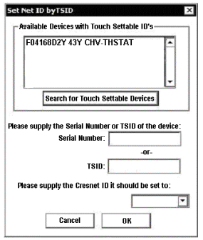
- Enter either the serial number or TSID number of the device that requires a change. The list scrolls to and highlights the device listing. The listing should show the device’s default Cresnet ID (a.k.a. Net ID).
- Enter the Cresnet ID that the device should be set to and click OK. The number you enter should appear on the list.
- CAUTION: This function does not prevent you from setting duplicate IDs. Be sure to check current assignments before entering the desired Cresnet ID number.
Serial Number to TSID Conversion
This utility is useful in a case where there are multiple devices of the same type on a network, you need to locate a particular one, you know the TSID but not the serial number, and your site installation list is based on device serial numbers. In this (or the reverse) situation, do the following:
- Open the Crestron Viewport.
- From the Viewport menu, select Functions | Serial Number
 TSID Conversion Tool. The “Serial NumberTSID Conversion Tool” window is displayed.
“Serial Number to TSID Conversion Tool” Window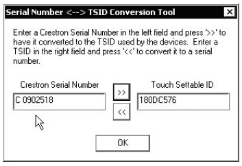
- Enter the serial number or TSID number as instructed; press the appropriatebutton to obtain the corresponding number.
NOTE: Enter serial numbers, including spaces, exactly as they appear on the unit label. Alpha characters in serial numbers or TSID numbers may be entered in upper or lower case.
Wiring Diagrams
The wiring diagrams that follow show connections for the CHV-TSTAT and CHV-THSTAT. The heating or cooling system can supply power to the thermostat, or a separate transformer can supply it. In many installations, spare conductors are available to supply 24 VAC to the thermostat, using the C (24 VAC common) connection on the HVAC equipment.
The P4 jumper internally connects either the RH (Reference Heat system) or RC (Reference Cooling system), relieving the installer from connecting a jumper from the 24(R) terminal to the RH or RC terminal.
If power is available from the HVAC system, follow the diagrams for the proper P4 jumper connection.
When power is not available from the HVAC system, a separate transformer, connected between 24(R) and 24(C) terminals, can provide power to the thermostat. When powered by a separate transformer, ensure that the P4 jumper is connected across pins 2 and 3 (No Connection) to prevent damage to the thermostat and the HVAC system.
CAUTION: The P4 Jumper Position on the Circuit Board is critical to proper operation. Improper P4 jumper position can cause equipment damage. The P4 jumper connects the 24(R) terminal to the RH, or RC connector. Refer to the following illustration.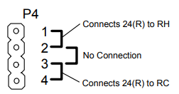
NOTE: Ensure that the power circuits are shut off at the source before connecting the thermostat. Provide disconnect means and overload protection as required for the power supply. Ensure that the transformer has sufficient power for all the thermostats in the system, or use multiple transformers. Refer to the power requirements in “Specifications” on page 3.
The following diagrams are examples of connections for heat, heat/cool and one-stage and two-stage heat pump systems, and various slab systems.
NOTE: Use either connector O or B as required, for changeover control.
Separately Powered Two Wire Heat
(Powered by an Independent Transformer)
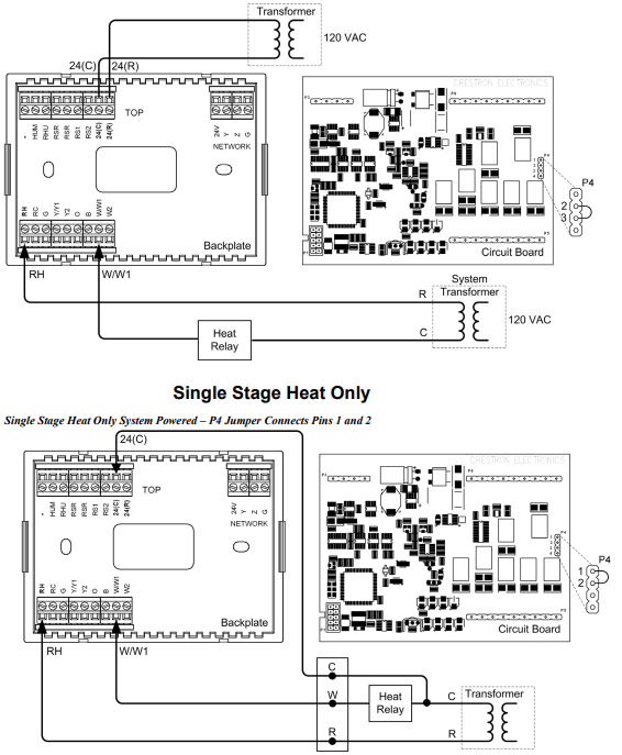
Single Stage Heat with Fan Control
Single Stage Heat with Fan Control – P4 Connects Pins 1 and 2 – Additional Jumper Connects RH to RC 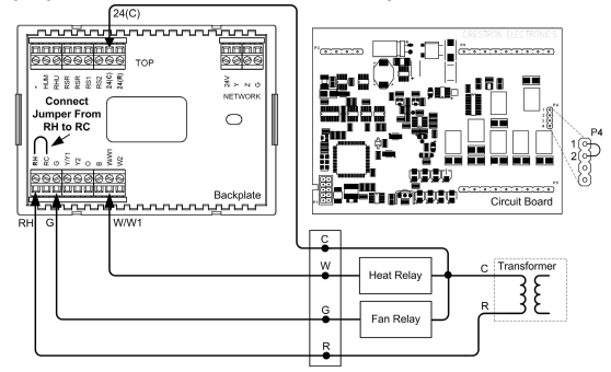
Single Stage Cool Only
Single Stage Cool Only – P4 Jumper Connects Pins 3 and 4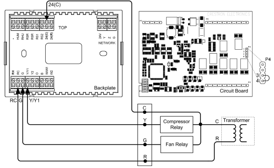
Single Stage Heat/Cool with Integrated Control Unit
Single Stage Heat/Cool with Integrated Control Unit – P4 Jumper Connects Pins 1 and 2 – Additional Jumper RH to RC
Single Stage Heat/Cool with Separate Systems
Single Stage Heat/Cool with Separate Systems – Heating System Powered – P4 Jumper Connects Pins 1 and 2 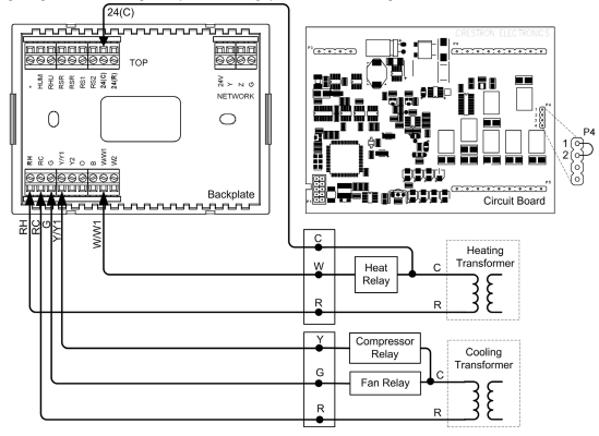
Single Stage Heat Pump
Single Stage Heat Pump – P4 Jumper Connects Pins 3 and 4– Additional Jumper RH to RC 
Two Stage Heat Pump
Two Stage Heat Pump System – P4 Jumper Connects Pins 3 and 4 – Additional Jumper RH to RC
Slab 1, Slab 2, and Slab 3 Systems (Floor Warming and/or Space Heating)
Slab 1, Slab 2, and Slab 3 Systems (Floor Warming and/or Space Heating) – P4 Jumper Connects Pins 1 and 2 
Slab 4A Two Stage Heat/Single Stage Cool Systems, Slab 5A Floor Warming with Single Stage Space Heat/Cool
Heat/Cool Style Connections
Slab 4A – P4 Jumper Connects Pins 1 and 2 – Jumper Connects RH to RC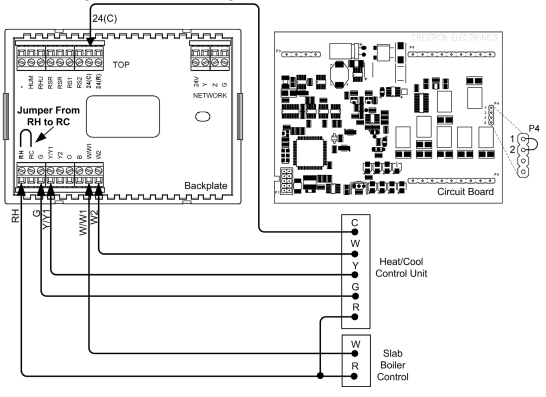
Slab 4B Two Stage Heat/Single Stage Cool System, Slab 5B Single Stage Heat/Cool with Floor Warming
Heat Pump Style Connections
Slab 4B – P4 Jumper Connects Pins 3 and 4 – Additional Jumper Connects RH to RC 
General Humidifier Connections
Installation
The location of the thermostat can affect its performance and efficiency. Install the thermostat away from direct sunlight, drafts, doorways, skylights, and windows. Also make sure the thermostat is conveniently located for programming, and do not mount on an exterior wall. The thermostats may be mounted directly to drywall or to a single-gang box. Thermostats and sensors are mounted 60 inches (152.4 cm) above the finished floor (HVAC industry standard). Refer to the following illustrations. Do the following to install the CHV-TSTAT or the CHV-THSTAT.
NOTE: When installing directly on drywall, use anchoring screws and hardware. Make sure the back of the thermostat is flush with drywall and the unit is level.
Required Hardware
- Thermostat
- Phillips screwdriver (not supplied)
- Two 6/32 x 1 inch panhead screws (supplied) for mounting to a single-gang box
- Single-gang box (not supplied)
- Wall anchors (not supplied) and screws (not supplied) for mounting directly to drywall
- Separate thermostat front plate from back plate (you may need to exert force when removing the faceplate).
- Turn off the circuit breaker when connecting power to the thermostat, and connect wiring as required (wiring goes through center hole on back plate).
NOTE: Ensure the correct position of the P4 jumper; refer to pages 12 through 21. - Attach back plate to drywall with screws and anchors (anchor hardware not provided) 60 inches above the finished floor. Thermostat may also be mounted to a single-gang box mounted horizontally, using the two 6/32 x 1 inch panhead screws provided. If using a five-sided single-gang box, fill with insulation material to minimize wall air ingress. Ensure that the thermostat is level and the ventilation holes in the backplate are not blocked.
- Note orientation of front plate connection leads and reattach the front plate on the back plate (make sure front plate snaps in place and no wires are pinched).
NOTE: If replacing an existing thermostat, make note of the wire colors and positions before removing the old thermostat.Install insulation in the gang box to prevent inaccurate readings.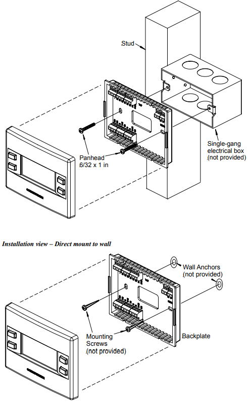
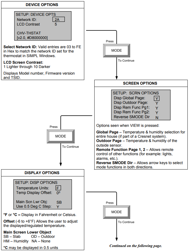
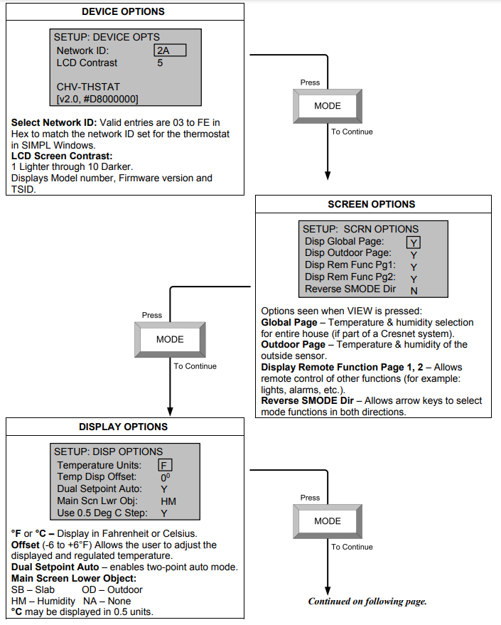
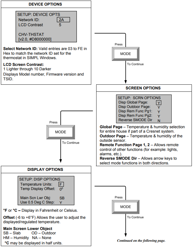
Thermostat Setup and Operation
Setup Procedure
After the thermostat is installed, it is necessary to set it up for a particular
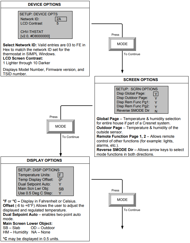
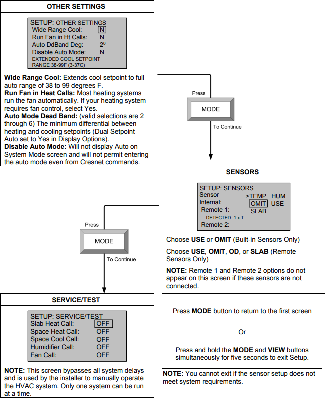
heating/cooling system. There are nine types of heating and cooling systems. Each system type is setup using nine screens. The available choices displayed on the setup screens depend on the type of system selected. Follow these directions to access the setup screens.
- Press and hold the MODE and VIEW buttons simultaneously for five seconds to access the setup menus.
- Press VIEW to select the parameter. A box appears around the selected parameter.
- Press the Arrow keys (▲▼) to choose the value of the selected parameter.
- Use the MODE button to advance to the next setup screen.
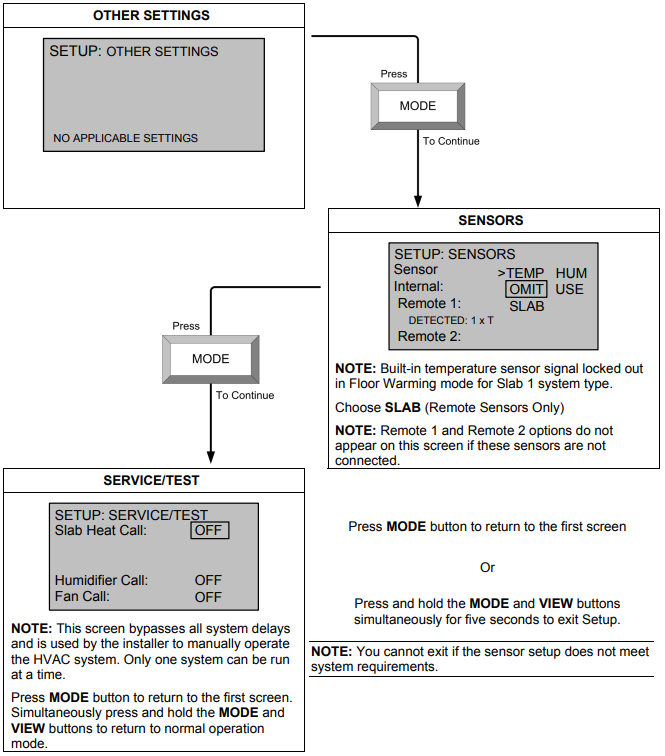
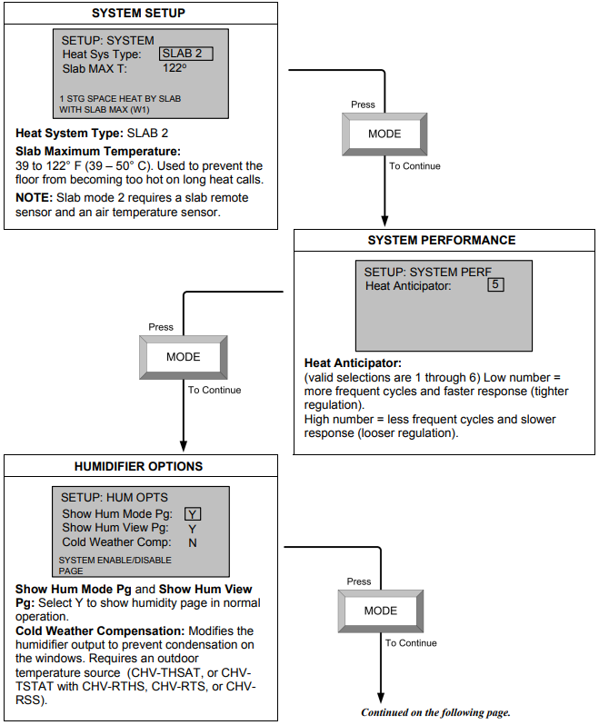
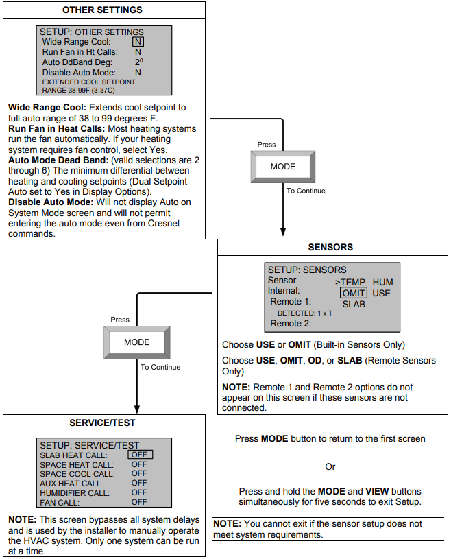
Setup Notes
The following are general setup notes.
NOTE: Refer to “System Connections” on page 8 for remote sensor connections to the thermostat.The Offset option permits recalibration of the room temperature sensor. There are various reasons why users may want to adjust the temperature. The selection number is the number of degrees added or subtracted to the actual temperature. The range is -6° to +6°F. Factory default is 0°. This adjustment changes the actual regulated temperature, not just the display.
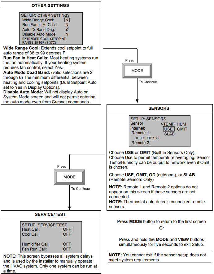
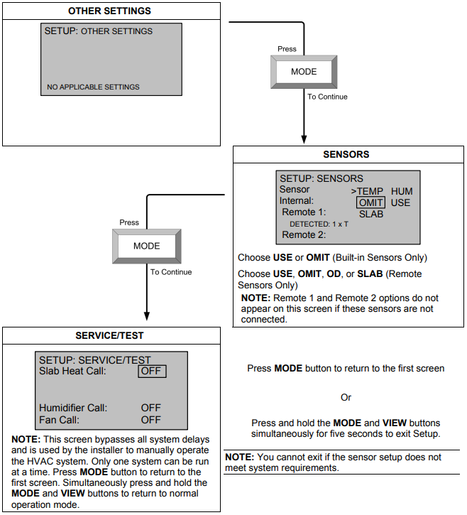
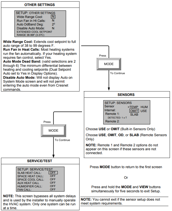
NOTE: The sensors are used for temperature and humidity averaging. Choose USE to include each sensor, or OMIT to exclude each sensor in the averaging equation. Sensors that have the same designation (for example, outdoor) are averaged together.
- The thermostat will not leave the setup mode unless a valid sensor selection is made.
- When the Reverse SMODE Dir (reverse system mode direction) selection is set to Yes on the Screen Options page, the arrow keys (▲ ▼) can be used to select system mode functions in both directions.
- If an out-of-range setpoint is entered, the setpoint is assigned its limit value in that direction.
- The Screen Options selected in setup are seen when the view key is pressed in normal operation.
System Types and Definitions
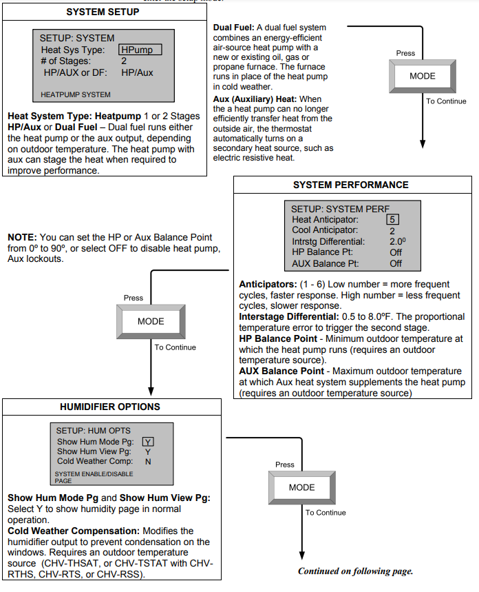
The first setup choice is the heat system type. There are three main types of heating/cooling systems.
- Heat/Cool, Radiant Heat or Forced Air Heating/Cooling, 1 or 2 Stages
- Heat Pump, 1 or 2 Stages, Auxiliary Heat or Dual Fuel
- Slab System (Slab1 through Slab 5B)
- Heat/Cool Systems Definitions
Radiant Heat systems: Radiant heat is a form of hydronic (hot water) heat that circulates hot water through pipes (baseboard radiation systems) or special tubing and installs on the perimeter of the house or underneath floors.
Forced Air systems: In a ducted heating/cooling system, a large fan
(blower) forces heated air from the furnace into the ducts and enters the rooms through a register or grill in the floor or wall.
One or Two Stages: Unlike traditional furnaces that turn on and run at full capacity with each demand for heating, two-stage furnaces operate like two separate furnaces. The unit begins to run in its first stage, and operates at a fraction of its heating capacity. This reduced capacity is sufficient on mild winter days. On very cold days, the furnace adjusts to full capacity (second stage) to meet the demand for heat.
Heat/Cool system setup begins on. - Heat Pump Systems Definitions
A heat pump extracts available heat from one area and transfers it to another. Even cold air contains some heat, and heat pumps can extract heat from the outside air on a cold day and transfer it indoors to maintain a comfortable temperature. A heat pump also works in reverse during the summer, extracting heat from indoors and transferring it outdoors.
Dual Fuel: A dual fuel system combines an energy-efficient air-source heat pump with a new or existing oil, gas or propane furnace. The furnace runs in place of the heat pump in cold weather.
Aux (Auxiliary) Heat: When the a heat pump can no longer efficiently transfer heat from the outside air, the thermostat automatically turns on a secondary heat source, such as electric resistive heat.
Heat pump system setup begins on. - 3. Slab Systems
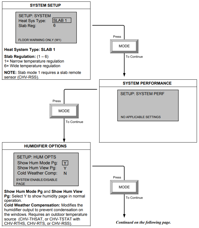
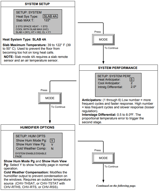
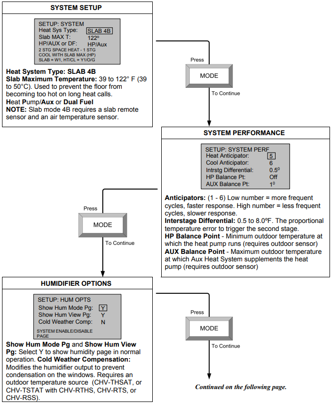
Slab heating works from the ground up. The heating components are installed below the floor or are embedded in a concrete slab. Heat radiates from the floor to warm the space above. The CHV-TSTAT and CHV-THSTAT support seven variations of slab heat systems.- SLAB 1: Floor warming only. Operates the slab heat to maintain a particular air temperature using the slab to heat the space. Will not heat over the slab maximum temperature even if this results in the space being under-heated. Connection to the slab output relay is terminal W1. Refer to setup on
- SLAB 3: One stage space heat with slab maximum and slab minimum. Performs the same operation as SLAB 2, and also keeps the slab at least as warm as slab setpoint. This may result in the space being overheated to maintain the slab minimum temperature. Connection to the slab output relay is terminal W1. Refer to setup on.
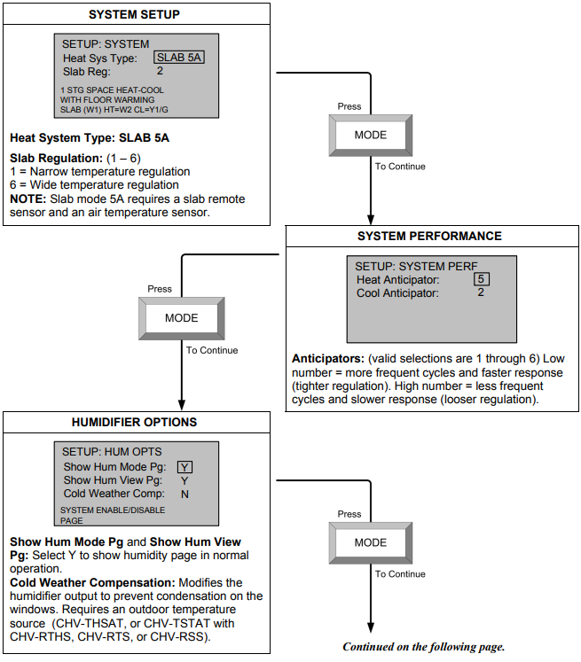
- SLAB 4A: Two-stage space heat with slab maximum and one stage cool. Maintains the air temperature using the slab for heat, up to the slab maximum. Augments the air heating by using a second stage of heat (generally a forced air system). Allows the second stage to operate by itself should the slab reach is maximum temperature and shut off. Cools the space with cooling call. Intended for heat-cool type forced air systems, with relay output connections to terminal W1 for slab, terminal W2 for 2nd stage heat, and terminal Y1 for cooling. Refer to setup on.
- SLAB 4B: Same operation as SLAB4A, but intended for a heat pump type second stage. Relay output connections are terminal W1 for slab heat, with heat pump-type connections on terminals Y1/O/G for cooling and heating calls. Aux heat is on terminal W2. Refer to setup on.
- SLAB 5A: One stage space heat and cool with floor warming. Combines the operation of a space heating/cooling thermostat with a floor-warming thermostat. Maintains the slab at slab setpoint, and maintains the space at the heat, cool, or auto setpoints. Systems effectively operate independently. Heat/Cool/Auto/Off sets the space control modes, and Floor Warming HEAT/OFF sets the slab mode. Intended for heat-cool style systems, with slab connection on terminal W1, space heat on terminal W2, and space cool on terminal Y1. Refer to setup on .
- SLAB 5B: Same as SLAB5A, but for heat pump space systems, with slab heat on terminal W1, and space heat/cool on terminals Y1/O/G. Aux heat is on terminal W2. Refer to setup on on terminal W1, and space heat/cool on terminals Y1/O/G. Aux heat is on terminal W2. Refer to setup on.
- Heat/Cool Systems Definitions
Heat/Cool, 1 or 2 Stages, Forced Air or Radiant
Press and hold the MODE and VIEW buttons simultaneously for five seconds to enter setup.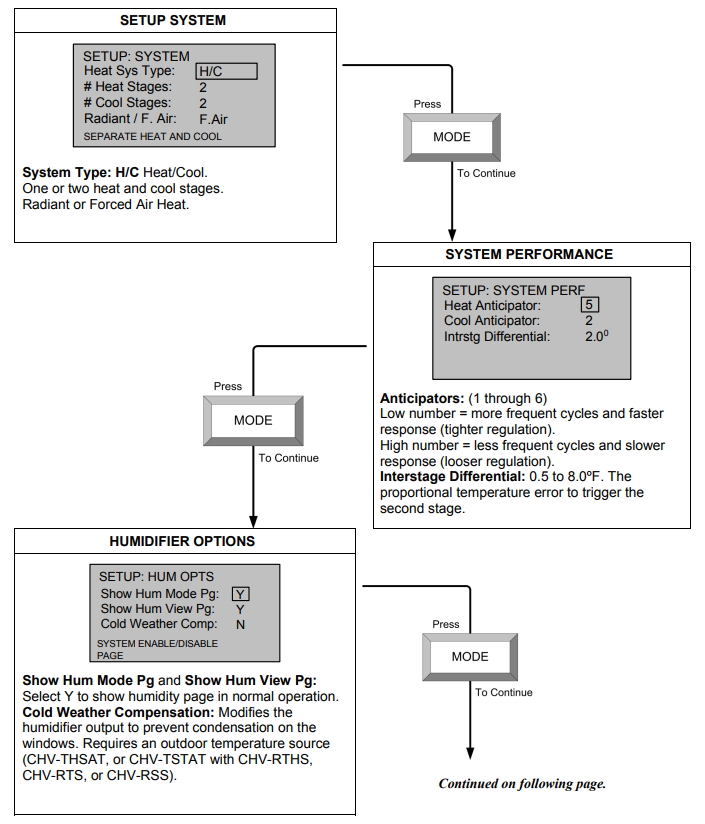
Heat Pump, 1 or 2 Stages, Aux Heat or Dual Fuel
Press and hold the MODE and VIEW buttons simultaneously for five seconds to enter the setup mode.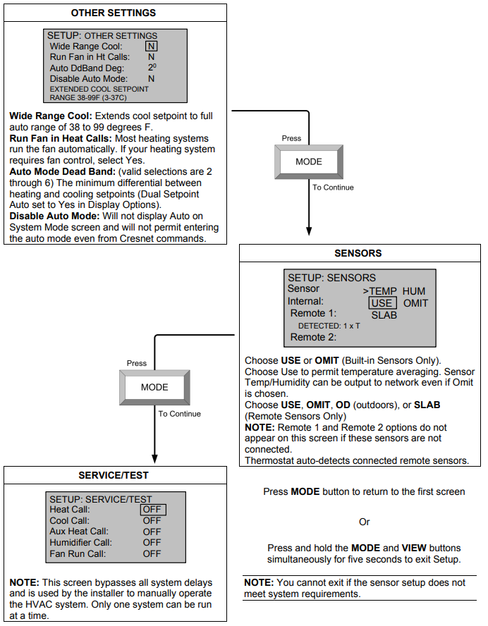
 Slab 1 – Floor Warming Only
Press and hold the MODE and VIEW buttons simultaneously for five seconds to enter the setup mode.
Slab 2 – Single Stage Space Heat with Slab Maximum
Press and hold the MODE and VIEW buttons simultaneously for five seconds to enter the setup mode.
Slab 3 – Single Stage Heat with Slab Minimum/Maximum
Press and hold the MODE and VIEW buttons simultaneously for five seconds to enter setup mode.
Slab 4A – Two Stage Heat/One Stage Cool with Slab Maximum
Press and hold the MODE and VIEW buttons simultaneously for five seconds to enter setup mode.

Slab 4B – 2 Stage Heat/1 Stage Cool with Slab Maximum (Heat Pump)
Press and hold the MODE and VIEW buttons simultaneously for five seconds to enter setup mode.
 Slab 5A – 1 Stage Heat/Cool with Floor Warming
Press and hold the MODE and VIEW buttons simultaneously for five seconds to enter setup mode.
Slab 5B – 1 Stage Heat/Cool with Floor Warming (Heat Pump)
Press and hold the MODE and VIEW buttons simultaneously for five seconds to enter setup mode. Slab mode 5B requires a slab remote sensor and an air temperature sensor.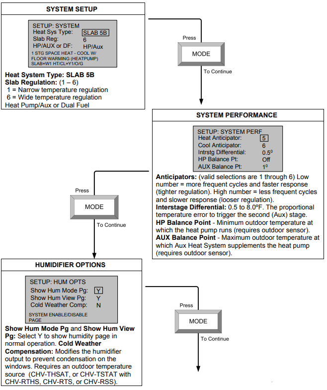
Operating the Thermostat
After setup, configure the thermostat using the following screens. 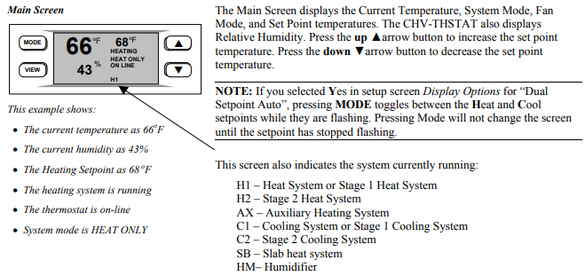
NOTE: System indicators flash to indicate short cycle timer protection (timer guards) engaged.
MODE MODE Button
It may also be necessary to access the following series of screens. Pressing the MODE button allows the user to access the following screens:
- System Mode screen and/or Slab System Mode screen(s)
- Fan Mode screen
- Humidifier screen
- Crestron System screen
- Global Update screen
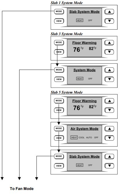
System Mode or Slab System Mode
- The “System Mode” screen appears when the MODE button is initially pressed. Use the up ▲and down ▼arrow buttons to select HEAT, COOL, AUTO, OFF or AUX HEAT ONLY.
- If your system is SLAB 1, SLAB 3, or SLAB 5, the Slab System Mode screens appear as described on the following page.
System Mode Screen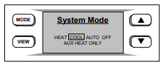
NOTE: The AUTO selection allows the system to switch between Heat and Cool automatically as needed to maintain the temperature.The AUX HEAT ONLY is for the backup heating system on Heat Pump based systems only. It allows the backup system to operate without operating the heat pump.The Slab 2 System Mode screen offers HEAT and OFF choice only.
Slab System Mode Screens
Slab 1 System Mode
- Press MODE button to continue to “2. Fan Mode” screen on the following page.
- Displays current floor warming temperature and setpoint.
- Press MODE button for System Mode screen.
- Press MODE button to continue to “2. Fan Mode” screen on the following page.
- Displays current floor warming temperature and setpoint. Press MODE button to continue to Air System Mode screen.
- Displays Air System Mode control.
- Press MODE button to continue to Slab System Mode screen.
- Press MODE button to continue to “2. Fan Mode” screen on the following page.
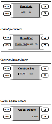
- Fan Mode
- Pressing the MODE button again displays the “Fan Mode” screen. Use the up ▲and down▼arrow buttons to select AUTO or ON.
NOTE: In AUTO, the fan runs only when the system calls for heat or cool. In ON, the fan runs continuously.
- Pressing the MODE button again displays the “Fan Mode” screen. Use the up ▲and down▼arrow buttons to select AUTO or ON.
- Humidifier
- Pressing the MODE button displays the “Humidifier” screen. This screen appears if enabled in setup and the thermostat is equipped with a humidity sensor.
- Use the up ▲and down ▼arrow buttons to select ENABLED or DISABLED.
- Crestron System
Pressing the MODE button again displays the “Crestron Sys” screen. Use the up ▲and down▼arrow buttons to select ONLINE or HOLD.- ONLINE – Data flows both ways, to and from the thermostat, enabling
adjustment from a remote location. - HOLD – Data flows one way, from the thermostat, blocking system commands to change the temperature and humidity when you do not want the current settings reset. Restores to the last command sent when online is re-engaged.
- ONLINE – Data flows both ways, to and from the thermostat, enabling
- Global Update
- Pressing the MODE button again displays the “Global Update” screen. Allows a single thermostat location to update the current temperature settings to all other thermostats on the system, provided that this function has been defined in the Crestron program.
- Press the down▼ button to send the update.
- Pressing the MODE button again returns you to the Main Screen
VIEW Button
The following screens are accessed by pressing the VIEW button:
- Humidity (If enabled in Setup)
- Outdoor (If enabled in Setup)
- Messages
NOTE: If enabled, the VIEW button also allows access to the remote button function screens. When part of a Cresnet system, the up ▲ and down ▼ arrow buttons can be used to enable other functions (i.e., lighting control, alarm system, etc.).
- Humidity
- Press the VIEW button to display the “Humidity” screen. The setpoint adjustment range is 5 – 70%.
- Use the up ▲and down ▼arrow buttons to adjust the Humidity Set Point level. This page only appears if enabled in the “HUM OPTS” setup screen and the thermostat is equipped with a humidity sensor.
NOTE: If a CHV-RTHS temperature/humidity sensor is installed, a CHV-TSTAT can import and display the humidity.
- Outdoor
- Press the VIEW button again to display the “Outdoor” screen. This allows the user to view the outdoor temperature (if an outdoor sensor has been installed) and outdoor humidity (if available). Outdoor temperature/humidity can come from an outdoor sensor wired directly to the thermostat or through the Cresnet system from another source. This page is only displayed if enabled in the “SCRN OPTIONS” setup screen.
NOTE: This is only a display and not for system activation. This display can be shown on either the CHV-TSTAT or the CHV-THSTAT.
- Press the VIEW button again to display the “Outdoor” screen. This allows the user to view the outdoor temperature (if an outdoor sensor has been installed) and outdoor humidity (if available). Outdoor temperature/humidity can come from an outdoor sensor wired directly to the thermostat or through the Cresnet system from another source. This page is only displayed if enabled in the “SCRN OPTIONS” setup screen.
- Messages
Press the VIEW button again to display the “Messages” screen. This screen allows the user to view any text messages sent from the control system (only when part of a Cresnet system). Text messages are limited to four lines, approximately 20 characters per line (including spaces). Allow for word wrap by staying within the 20 characters/spaces per line maximum. The thermostat auto-hyphenates when nearing the end of a line. You may use carriage returns to force a line change.
NOTE: This page is only seen when a message has been sent to the thermostat.
Press the MODE button to clear (CLR) the message(s). Acknowledges to the control system that the message has been read.
Programming Software
Have a question or comment about Crestron software?
Answers to frequently asked questions (FAQs) can be viewed in the Online Help section of the Crestron website (www.crestron.com). To post your own question or view questions you have submitted to Crestron’s True Blue Support, log in at http://support.crestron.com. First-time users will need to establish a user account.
- The CHV-TSTAT and CHV-THSTAT thermostats do not require programming when used as stand alone devices. Programming as part of a Cresnet system allows additional functionality, including:
- Global Update and Global Page display – Allows setting the temperature/humidity for an entire house in a multi-thermostat system.
- Remote Function pages – Allows system control of other functions (lighting, alarms, etc.). Two pages, two functions per page.
- System Messaging – Allows the control system to send text messages to the thermostat.
Setup is easy thanks to Crestron’s Windows-based programming software. The Crestron D3 Pro software creates a complete project, with no special programming required. D3 Pro completes all necessary programming for a base system including the control system program. Once D3 Pro creates the project, the system interfaces and program logic can be customized. It can also be modified with Crestron development tools (i.e., SIMPL Windows) software, although this should rarely be necessary.
The program output of D3 Pro is a SIMPL Windows program with much of the functionality encapsulated in macros. Therefore, extending the capabilities of the system is very easy. Crestron D3 Pro and SIMPL Windows are intended for users with different levels of programming knowledge. The flexibility of each is proportional to the degree of programming expertise (i.e., the more flexible, the more a programmer needs to know and account for). Of course, one can begin programming using the easiest method (Crestron D3 Pro) and use advanced techniques that are available from SIMPL Windows to customize the job.
D3 Pro comes with templates for all supported interfaces. If a user wishes to create a touchpanel project using templates with a different look-and-feel this can be accomplished by making a custom template. This custom template can then be used by D3 Pro to create the final project files. The following are recommended software version requirements for the PC:
- [Optional] D3 Pro version 1.1 or later. Requires SIMPL Windows.
- SIMPL Windows version 2.05.22 or later with library update 297.
- Requires SIMPL+ Cross Compiler version 1.1.
- Crestron Database version 16.3.0 or later if using D3 Pro.
Programming with Crestron D3 Pro
Crestron D3 Pro offers automatic programming for residential and commercial systems. The interface of this tool guides you through a few basic steps for designating rooms and specifying the control system, devices, and functionality. Crestron D3 Pro then programs the system, including all control system logic.
Crestron D3 Pro is fully integrated with the Crestron suite of software development tools and accesses these tools behind the scenes, enabling you to easily create robust systems. Both the older and newer versions of the thermostat models are supported.
- The easiest method of programming, but does not offer as much flexibility as SIMPL Windows.
Programming with SIMPL Windows
NOTE: The following assumes that the reader has knowledge of SIMPL Windows. If not, refer to the extensive help information provided with the software.
In the following description, the PRO2 control system is used. The slotted thermostat symbol described in this section is for 2-Series only.
SIMPL Windows is Crestron’s software for programming Crestron control systems. It provides a well-designed graphical environment with a number of workspaces (i.e., windows) in which a programmer can select, configure, program, test, and monitor a Crestron control system. SIMPL Windows offers drag and drop functionality in a familiar Windows® environment.
This section describes a sample SIMPL Windows program that includes a CHV-THSTAT.
Configuration Manager is where programmers “build” a Crestron control system by selecting hardware from the Device Library. In Configuration Manager, drag the PRO2 from the Control Systems folder of the Device Library and drop it in the upper pane of the System Views. The PRO2 with its associated communication ports is displayed in the System Views upper pane.
PRO2 System View
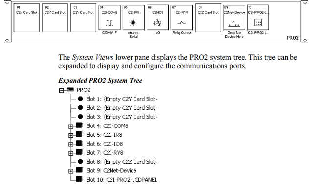
C2Net-Device Slot in Configuration Manager
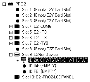
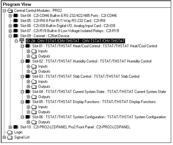
To incorporate a CHV-TSTAT or CHV-THSTAT into the system, drag the symbol for the thermostat from the Crestron Sensing Modules folder of the Device Library and drop it on C2NET-Device slot in System Views. The PRO2 system tree displays the thermostat symbol in Slot 9, with a default Net ID of 2A as shown in the example graphic below.
C2Net Device, Slot 9
Setting the Net ID in Device Settings
Double-click the thermostat icon in the upper pane to open the “Device Settings” window. This window displays the device information. Select the Net ID tab to change the Net ID, as shown in the following graphic.
“Device Settings” Window for the CHV-THSTAT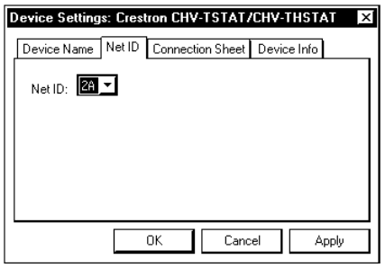
Thermostat Symbol in Programming Manager
Programming Manager is where programmers “program” a Creston control system by assigning signals to symbols.
This is a slotted symbol in which the functions are grouped together in six slots.
- Slot 1 – Heat Cool Control
- Slot 2 – Humidity Control
- Slot 3 – Slab Control
- Slot 4 – Current System State
- Slot 5 – Display Functions
- Slot 6 – System Configuration
NOTE: Because of changes to the symbol and other improved features, this version of the SIMPL Windows symbol is not compatible with previous firmware versions.
Program View of Slotted Symbol
NOTE: All temperatures, including setpoint values, are expressed in tenths of degrees. For example: sending 703 means 70.3.
The following are detail views of the six thermostat slots in the SIMPL windows symbol. Definitions of the symbol inputs and outputs follow each diagram.
Slot 1 Detail View – Heat/Cool Control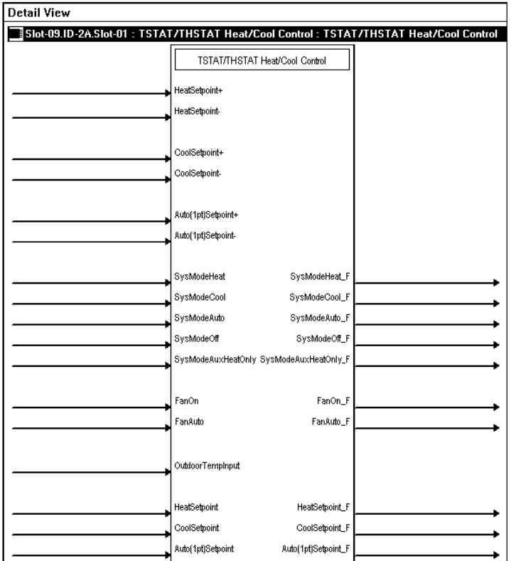
Slot 1- Heat/Cool Control Digital Joins
| SIGNAL | I/O | SIGNAL TYPE | DEFINITION |
| HeatSetpoint+ HeatSetpoint- CoolSetpoint+ CoolSetpoint- Auto(1pt)Setpoint+ Auto(1pt)Setpoint- | Input | Digital | Raises (+) or lowers (-) the temperature regulating setpoint for heat-only, cool-only and single point auto mode, on the rising edge of the input. The setpoint is adjusted in whole degrees Fahrenheit or Celsius, or half degrees Celsius if that option is selected. Thus if the analog value of the heat setpoint equals 700 (for 70°), a rising edge of <HeatSetpoint+> will raise the heat setpoint value to 710 (for 71°). Similarly, if the analog value of the cool setpoint equals 200 (for 20°) and the half- degree Celsius option is selected, a rising edge of
<CoolSetpoint-> will lower the cool setpoint value to 195 (for 19.5° C). Continuing to assert the up or down inputs at the limits of each setpoint will not affect the setpoint. That is, the setpoint will hold at its maximum or minimum setting. High/1 (rising edge) = Setpoint up or down; Low/0 = no effect |
| SysModeHeat SysModeCool SysModeAuto SysModeOff SysModeAuxHeatOnly | Input | Digital | Selects the system mode on the rising edge of the input:
Heat-only Cool-only Auto (auto selects heat or cool) Off (no HVAC operation) Auxiliary heat-only mode for heat pump systems (no effect on a heat/cool system). The staging for a particular mode does not affect these inputs. High/1 (rising edge) = Select system mode; Low/0 = no effect |
| SysModeHeat_F SysModeCool_F SysModeAuto_F SysModeOff_F
SysModeAuxHeatOnly_F |
Output | Digital | Reports the current system mode.
High/1 = System mode running; Low/0 = System mode not running |
| FanOn FanAuto | Input | Digital | Selects the fan mode on the rising edge of the input.
In On mode, the fan runs continually. In Auto mode, the fan runs only when the system calls for heat or cool. High/1 (rising edge) = Select fan mode; Low/0 = no effect |
| FanOn_F
FanAuto_F |
Output | Digital | Reports the current fan mode.
High/1 = Fan mode selected; Low/0 = Fan mode not selected |
| OutdoorTempInput | Input | Analog | Input that allows the outdoor temperature value to be retrieved from Cresnet for display on the “outdoor” page, This value is ignored when a thermostat has a remote-outdoor sensor connected to it. The temperature value is in tenths of a degree with no Fahrenheit or Celsius conversion. That is, the value is assumed to be in the native unit of the thermostat that is transmitting the temperature reading. Thus a value of 30 would display a temperature of 3° regardless of the temperature scale. If a heat pump thermostat does not have its own outdoor sensor, it may use this value for balance point action.* This is useful for multi-thermostat heat pump systems without discrete sensors.
*The heat pump balance point is the outdoor temperature below which heat pump operation is locked out, and auxiliary heat runs in place of it. The auxiliary balance point is the outdoor temperature above which auxiliary heat is locked out. |
| SIGNAL | I/O | SIGNAL TYPE | DEFINITION |
| HeatSetpoint CoolSetpoint Auto(1pt)Setpoint | Input | Analog | Sets the temperature regulating setpoint for heat-only, cool- only and single point auto mode in tenths of a degree. The scale (Fahrenheit or Celsius) is based on the current setting in the unit. The displayed setpoint value is rounded to whole degrees Fahrenheit or Celsius, or half degrees Celsius if that option is enabled. This means that if the value 721 is presented on the heat setpoint input, the thermostat LCD will display a setpoint of 72°. Similarly, if the value 204 is presented on the cool setpoint input and the half degree Celsius option is enabled, the thermostat LCD will display a setpoint of 20.5°.
Valid analog values are as follows: Heat setpoint: 380 to 890 (38° to 89°F); or 30 to 320 (3° to 32°C). Cool setpoint: 590 to 990 (59° to 99°F); or 150 to 370 (15° to 37°C). Cool setpoint (if wide-range cool mode is enabled): 380 to 990 (38° to 99°F); or 30 to 370 (3° to 37°C). Auto (1pt) setpoint: 380 to 990 (38° to 99°F); or 30 to 370 (3° to 37°C). The setpoints will saturate in both directions. Thus sending 0 will set the setpoint to its minimum value, while sending 1000 will set the setpoint to its maximum value. |
| HeatSetpoint_F CoolSetpoint_F Auto(1pt)Setpoint_F | Output | Analog | Reports the temperature regulating setpoint for heat-only, cool- only and single point auto mode, in tenths of a degree.
The scale (Fahrenheit or Celsius) is based on the current setting in the unit. |
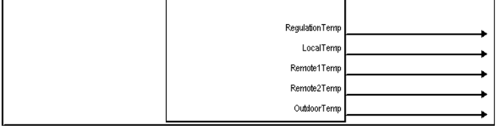
| RegulationTemp | Output | Analog | Reports the mean (averaged) temperature reading of all internal and remote sensors set to “Use”, in tenths of a degree. The scale (Fahrenheit or Celsius) is based on the current setting in the unit. Sensors are manually set to Use, Omit, OD (Outdoor) or Slab via the setup menus on the thermostat. |
| LocalTemp | Output | Analog | Reports the temperature reading of the internal temperature sensor, in tenths of a degree. The scale (Fahrenheit or Celsius) is based on the current setting in the unit. The internal sensor reading is reported regardless of the Use/Omit/OD designation. |
| Remote1Temp | Output | Analog | Reports the temperature reading of the Remote 1 temperature sensor, in tenths of a degree. The scale (Fahrenheit or Celsius) is based on the current setting in the unit. If two temperature sensors are connected to the Remote 1 channel, this is the mean temperature. The Remote 1 sensor readings are reported regardless of the Use/Omit/OD/Slab designation. |
| Remote2Temp | Output | Analog | Reports the temperature reading of the Remote 2 temperature sensor, in tenths of a degree. The scale (Fahrenheit or Celsius) is based on the current setting in the unit. If two temperature sensors are connected to the Remote 2 channel, this is the mean temperature. The Remote 2 sensor readings are reported regardless of the Use/Omit/OD/Slab designation. |
| SIGNAL | I/O | SIGNAL TYPE | DEFINITION |
| Outdoor Temp | Output | Analog | Reports the temperature reading of any sensors set to “OD” (Outdoor) in tenths of a degree. The scale (Fahrenheit or Celsius) is based on the current setting in the unit. If more than one sensor is set to OD, this is the mean outdoor temperature. Sensors are manually set to Use, Omit, OD (Outdoor) or Slab via the setup menus on the thermostat. |
Slot 2 Detail View – Humidity Control
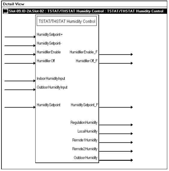
Slot 2 – Humidity Control
| SIGNAL | I/O | SIGNAL TYPE | DEFINITION |
| HumiditySetpoint+ HumiditySetpoint- | Input | Digital | Raises (+) or lowers (-) the humidity regulating setpoint on the rising edge of the input. Continuing to assert the up or down inputs at the limits of the setpoint will not affect the setpoint. That is, the setpoint will hold at its maximum or minimum setting. High/1 (rising edge) = Humidity setpoint up or down; Low/0 = no effect |
| HumidifierEnable | Input | Digital | Enables the humidifier on the rising edge of the input.
High/1 (rising edge) = Enable humidifier; Low/0 = no effect |
| HumidifierEnable_F | Output | Digital | Indicates that the humidifier is enabled.
High/1 = Humidifier ready to run; Low/0 = Humidifier not enabled |
| HumidifierOff | Input | Digital | Turns off the humidifier on the rising edge of the input.
High/1 (rising edge) = Turn off humidifier; Low/0 = no effect |
| HumidifierOff_F | Output | Digital | Indicates that the humidifier is off.
High/1 = Humidifier off; Low/0 = Humidifier enabled |
| IndoorHumidityInput | Input | Analog | Receives the indoor relative humidity from a sensor that is not connected to the thermostat, for display on the Main page of the thermostat LCD (CHV-THSTAT only).
This value is ignored if a humidity sensor (CHV-RTHS) is connected to the CHV-TSTAT. |
| OutdoorHumidityInput | Input | Analog | Receives the outdoor relative humidity from a sensor that is not connected to the thermostat, for display on the Outdoor page of the thermostat LCD.
This value is ignored if an outdoor humidity sensor (CHV-RTHS) is connected to the thermostat. |
| HumiditySetpoint | Input | Analog | Sets the humidity regulating setpoint in whole numbers. Valid values range from 5 to 70.
The humidity setpoint will saturate in both directions. Thus sending 0 will set the humidity setpoint to 5, and sending 80 will set the humidity setpoint to 70. |
| HumiditySetpoint_F | Output | Analog | Reports the humidity regulating setpoint. |
| RegulationHumidity | Output | Analog | Reports the mean (averaged) humidity reading of all internal and remote humidity sensors set to “Use”, in whole numbers. Only active when a thermostat setup has humidity sensing capability, either by being a CHV-THSTAT or a CHV-TSTAT with humidity remote.
Humidity sensors are manually set to Use, Omit, or Outdoor via the setup menus on the thermostat. |
| LocalHumidity | Output | Analog | Reports the relative humidity reading of the built-in humidity sensor (CHV-THSTAT only) in whole numbers.
The internal humidity sensor reading is reported regardless of the Use or Omit designation. |
| Remote1Humidity | Output | Analog | Reports the humidity reading of the Remote 1 humidity sensor in whole numbers.
The Remote 1 humidity reading is reported regardless of the Use/Omit/OD designation. |
| SIGNAL | I/O | SIGNAL TYPE | DEFINITION |
| Remote2Humidity | Output | Analog | Reports the humidity reading of the Remote 2 humidity sensor in whole numbers.
The Remote 2 humidity sensor reading is reported regardless of the Use/Omit/OD designation. |
| OutdoorHumidity | Output | Analog | Reports the humidity reading of any humidity sensor set to “OD” (Outdoor) in whole numbers.
If more than one humidity sensor is set to OD, this is the mean outdoor humidity. Humidity sensors are manually set to Use, Omit, or Outdoor via the setup menus on the thermostat. |
Slot 3 Detail View – Slab Control
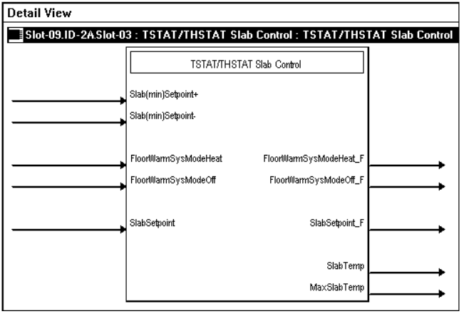
Slot 3 – Slab Control
| SIGNAL | I/O | SIGNAL TYPE | DEFINITION |
| Slab(min)Setpoint+ Slab(min)Setpoint- | Input | Digital | Raises (+) or lowers (-) the slab regulating setpoint on the rising edge of the input.
The setpoint is adjusted in whole degrees Fahrenheit or Celsius, or half degrees Celsius if that option is selected. Thus if the analog value of the slab setpoint equals 700 (for 70°), a rising edge of <Slab(min)Setpoint+> will raise the slab setpoint value to 710 (for 71°). Similarly, if the analog value of the slab setpoint equals 200 (for 20°) and the half-degree Celsius option is selected, a rising edge of <Slab(min)Setpoint-> will lower the setpoint value to 195 (for 19.5°C). Continuing to assert the up or down inputs at the limits of each setpoint will not affect the setpoint. That is, the setpoint will hold at its maximum or minimum setting. High/1 (rising edge) = Slab setpoint up or down; Low/0 = no effect |
| FloorWarmSysModeHeat FloorWarmSysModeOff | Input | Digital | Turns the floor-warming system on or off on the rising edge of the input.
High/1 (rising edge) = Turn floor-warming system On/Off; Low/0 = no effect |
| FloorWarmSysModeHeat_F
FloorWarmSysModeOff_F |
Output | Digital | Reports the status of the floor-warming system.
High/1 = Floor-warming system On/Off |
| SlabSetpoint | Input | Analog | Sets the slab regulating setpoint in tenths of a degree. The scale (Fahrenheit or Celsius) is based on the current setting in the unit.
The displayed setpoint value is rounded to whole degrees Fahrenheit or Celsius, or half-degrees Celsius if that option is enabled. This means that if the value 721 is presented on the slab setpoint input, the thermostat LCD will display a slab setpoint of 72°. Similarly, if the value 204 is presented on the slab setpoint input and the half-degree Celsius option is enabled, the thermostat LCD will display a slab setpoint of 20.5°. Valid analog values range from 380 to 1210 (38° to 121°F); or 3 to 495 (3° to 49.5°C). The setpoints will saturate in both directions. Thus sending 0 will set the setpoint to its minimum value, while sending 1300 will set the setpoint to its maximum value. |
| SlabSetpoint_F | Output | Analog | Reports the slab regulating setpoint in tenths of a degree. The scale (Fahrenheit or Celsius) is based on the current setting in the unit. |
| SlabTemp | Output | Analog | Reports the temperature reading of any remote sensor set to “Slab”, in tenths of a degree. The scale (Fahrenheit or Celsius) is based on the current setting in the unit.
If more than one sensor is set to “Slab”, this is the mean slab temperature. Sensors are set to Use, Omit, OD (Outdoor) or Slab via the setup menus on the thermostat. |
| SIGNAL | I/O | SIGNAL TYPE | DEFINITION |
| MaxSlabTemp | Output | Analog | Reports the maximum slab temperature value. The scale (Fahrenheit or Celsius) is based on the current setting in the unit.
Values range from 390 to 1220 (39° to 122°F); or 44 to 500 (4° to 50°C).
This value is always at least one degree higher than the slab setpoint, but is disabled in floor-warming system types (Slab1, 5A/5B). |
Slot 4 Detail View – Current System State
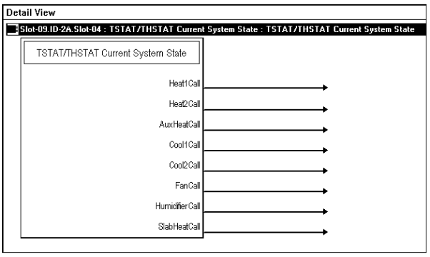
Slot 4 – Current System State
| SIGNAL | I/O | SIGNAL TYPE | DEFINITION |
| Heat1Call | Output | Digital | Goes high when the system calls for heat or stage 1 heat. Remains high for as long as the heat system is running.
High/1 = Heat/Stage 1 heat running; Low/0 = System not running |
| Heat2Call | Output | Digital | Goes high when the system calls for stage 2 heat. Remains high for as long as the heat system is running.
High/1 = Stage 2 heat running; Low/0 = System not running |
| AuxHeatCall | Output | Digital | Goes high when the system calls for auxiliary heat. Remains high for as long as the emergency heat system is running.
High/1 = Aux heat running; Low/0 = System not running |
| Cool1Call | Output | Digital | Goes high when the system calls for cool or stage 1 cool. Remains high for as long as the cool system is running.
High/1 = Cool/Stage 1 cool running; Low/0 = System not running |
| SIGNAL | I/O | SIGNAL TYPE | DEFINITION |
| Cool2Call | Output | Digital | Goes high when the system calls for stage 2 cool. Remains high for as long as the cool system is running.
High/1 = Stage 2 cool running; Low/0 = System not running |
| FanCall | Output | Digital | Goes high when the fan is running for any reason. Remains high for as long as the fan is running.
High/1 = Fan running; Low/0 = System not running |
| HumidifierCall | Output | Digital | Goes high when the system calls for humidification. Remains high for as long as the humidifier is running.
High/1 = Humidifier running; Low/0 = System not running |
| SlabHeatCall | Output | Digital | Goes high when the system calls for slab heat. Remains high for as long as the slab system is running.
High/1 = Slab heat running; Low/0 = System not running |
Slot 5 Detail View – Display Functions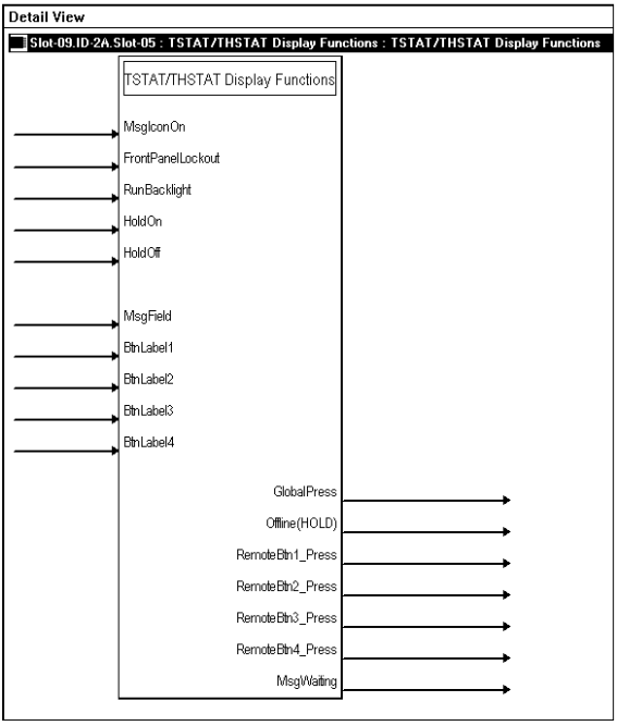
Slot 5 – Display Functions
| SIGNAL | I/O | SIGNAL TYPE | DEFINITION |
| MsgIconOn | Input | Digital | Alternately flashes the text “View Msg” with “Online/Hold, Net Fault” on the Main page of the thermostat LCD, for as long as the input remains high. This alerts the user to check for a displayed message on the Messages page of the thermostat LCD.
High/1 = Flash message icon; Low/0 = No message icon |
| FrontPanelLockout | Input | Digital | Locks out the four hard pushbuttons on the thermostat for as long as the input remains high. In this mode, pressing the buttons will have no effect. Automatically disabled in case of system error or failure.
High/1 = Lock out buttons; Low/0 = Enable button operation |
| RunBacklight | Input | Digital | Turns on the thermostat’s backlight for eight seconds on the rising edge of the input.
High/1 (rising edge) = Turn on backlight; Low/0 = no effect |
| HoldOn | Input | Digital | Turns on the Hold function on the rising edge of the input.
When “on hold”, data flows one way, from the thermostat to Cresnet. All Cresnet commands to the thermostat are blocked except for the Hold Off command. While the thermostat is on hold it buffers all setpoint and mode changes (except for up/down inputs). The setpoints and mode inputs will take effect immediately when the hold is released. High/1 (rising edge) = Enable Hold mode; Low/0 = no effect |
| HoldOff | Input | Digital | Turns off the Hold function, on the rising edge of the input.
In this mode, the thermostat is put back online and data flows freely between the Cresnet network and the thermostat. While the thermostat is “on hold” it buffers all setpoint and mode changes (except for up/down inputs). The setpoints and mode inputs will take effect immediately when the hold is released. High/1 (rising edge) = Restore Cresnet communication and buffered settings; Low/1 = no effect |
| MsgField | Input | Serial | Sends text string to the Messages page of the thermostat LCD.
Displayed text is limited to approximately 20 characters per line (including spaces) to a maximum of four lines. The thermostat supports word wrap and auto-hyphenation within the 20 characters/spaces per line maximum. (Carriage returns will force a line change.) |
| BtnLabel1 | Input | Serial | Sends text label for display next to the Remote Function Button 1 (Up pushbutton) on Remote Page 1 of the thermostat LCD.
The thermostat LCD provides two Remote pages in which the Up and Down pushbuttons operate as remote function buttons. In this mode the buttons can trigger non-HVAC functions such as AV control, lighting, or alarm activation. |
| BtnLabel2 | Input | Serial | Sends text label for display next to the Remote Function Button 2 (Down pushbutton) on Remote Page 1 of the thermostat LCD.
The thermostat LCD provides two Remote pages in which the Up and Down pushbuttons operate as remote function buttons. In this mode the buttons can trigger non-HVAC functions such as AV control, lighting, or alarm activation. |
| SIGNAL | I/O | SIGNAL TYPE | DEFINITION |
| BtnLabel3 | Input | Serial | Sends text label for display next to the Remote Function Button 3 (Up pushbutton) on Remote Page 2 of the thermostat LCD.
The thermostat LCD provides two Remote pages in which the Up and Down pushbuttons operate as remote function buttons. In this mode the buttons can trigger non-HVAC functions such as AV control, lighting, or alarm activation. |
| BtnLabel4 | Input | Serial | Sends text label for display next to the Remote Function Button 4 (Down pushbutton) on Remote Page 2 of the thermostat LCD.
The thermostat LCD provides two Remote pages in which the Up and Down pushbuttons operate as remote function buttons. In this mode the buttons can trigger non-HVAC functions such as AV control, lighting, or alarm activation. |
| GlobalPress | Output | Digital | Briefly pulses high whenever the Send button of the Global Update page is pressed.
This signal can be tied to logic in the program to trigger functions such as global updates of temperature or humidity values. |
| Offline(HOLD) | Output | Digital | Indicates that the thermostat has been taken offline. In this mode, the thermostat is “on hold” and data flows one way, from the thermostat to Cresnet. All Cresnet commands to the thermostat are blocked except for the Hold Off command. While the thermostat is “on hold” it buffers all setpoint and mode changes (except for up/down inputs). The setpoints and mode inputs will take effect immediately when the hold is released.
Remains high for as long as the thermostat is offline. High/1 = Offline; Low/0 = Online |
| RemoteBtn1_Press | Output | Digital | Indicates that Remote Function Button 1 (Up pushbutton) has been pressed on Remote Page 1 of the thermostat LCD. Remains high for as long as the button is pressed.
The thermostat LCD provides two Remote pages in which the Up and Down pushbuttons operate as remote function buttons. In this mode the buttons can trigger non-HVAC “remote” functions such as AV control, lighting, or alarm activation. |
| RemoteBtn2_Press | Output | Digital | Indicates that Remote Function Button 2 (Down pushbutton) has been pressed on Remote Page 1 of the thermostat LCD. Remains high for as long as the button is pressed.
The thermostat LCD provides two Remote pages in which the Up and Down pushbuttons operate as remote function buttons. In this mode the buttons can trigger non-HVAC “remote” functions such as AV control, lighting, or alarm activation. |
| RemoteBtn3_Press | Output | Digital | Indicates that Remote Function Button 3 (Up pushbutton) has been pressed on Remote Page 2 of the thermostat LCD. Remains high for as long as the button is pressed.
The thermostat LCD provides two Remote pages in which the Up and Down pushbuttons operate as remote function buttons. In this mode the buttons can trigger non-HVAC “remote” functions such as AV control, lighting, or alarm activation. |
| SIGNAL | I/O | SIGNAL TYPE | DEFINITION |
| RemoteBtn4_Press | Output | Digital | Indicates that Remote Function Button 4 (Down pushbutton) has been pressed on Remote page 2 of the thermostat LCD. Remains high for as long as the button is pressed.
The thermostat LCD provides two Remote pages in which the Up and Down pushbuttons operate as remote function buttons. In this mode the buttons can trigger non-HVAC “remote” functions such as AV control, lighting, or alarm activation. |
| MsgWaiting | Output | Digital | Indicates that text has been sent to the Messages page of the thermostat LCD, via the <MsgField> input.
Remains high until the user presses the Clear button on the Messages page. |
Slot 6 Detail View – System Configuration
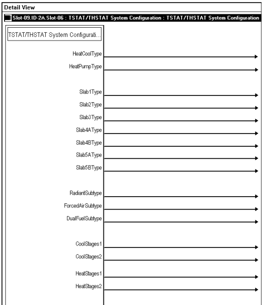
Slot 6 – System Configuration
| SIGNAL | I/O | SIGNAL TYPE | DEFINITION |
| HeatCoolType HeatPumpType Slab1Type Slab2Type Slab3Type Slab4AType Slab4BType Slab5AType
Slab5BType |
Output | Digital | Indicates the heat/cool or slab system type that has been selected. Remains high for as long as the corresponding system is selected.
The thermostats support single-stage and multi-stage heating and cooling systems, including conventional fossil fuel systems, heat pumps with auxiliary heat and slab heating systems. High/1 = System selected; Low/0 = System not selected |
| RadiantSubtype ForcedAirSubtype DualFuelSubtype | Output | Digital | Indicates the subtype for heating/cooling systems. Remains high for as long as the corresponding subtype is selected.
Radiant heating turns large areas (floor, walls, ceilings) into large surface radiators. Forced air is a type of heating system that uses a blower motor to move air through the furnace and into the ductwork. In dual-fuel setups, the auxiliary heat output runs in place of the heat pump in cold weather. High/1 = Subtype selected; Low/0 = Subtype not selected |
| CoolStages1 CoolStages2 HeatStages1
HeatStages2 |
Output | Digital | Indicates how many stages of cooling or heating there are in the system.
High/1 = One or two-stage system; Low/0 = System type not selected |
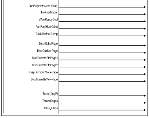
| DualSetpoints(AutoMode) | Output | Digital | Indicates that dual-point auto mode has been enabled. Remains high for as long as the mode is enabled.
High/1 = Dual-point auto mode enabled; Low/0 = Not enabled |
| NoAutoMode | Output | Digital | Reports whether Auto Mode is permitted in the system. If enabled, the thermostat will not display Auto on the System Mode screen and will not permit the thermostat to enter the auto mode even from Cresnet commands.
High/1 = No Auto Mode; Low/0 = Auto Mode permitted |
| WideRangeCool | Output | Digital | Indicates that wide range cool mode has been enabled. Remains high for as long as the mode is enabled.
Wide range cool extends the cool setpoint range to the full auto range of 38° to 99°F, or 3° to 37°C. This is suitable for wine cellars or other colder chilling processes. High/1 = Wide range cool enabled; Low/0 = Not enabled |
| RunFan(HeatCalls) | Output | Digital | Indicates that Run Fan in Heat Calls has been enabled. Remains high for as long as the mode is enabled.
Run Fan in Heat Calls is a device setting that activates the fan output with W1/W2 heat calls. Does not enable operation on slab systems on the slab (W1) call. High/1 = Run Fan in Heat Calls enabled; Low/0 = Not enabled |
| SIGNAL | I/O | SIGNAL TYPE | DEFINITION |
| ColdWeatherComp | Output | Digital | Indicates that cold weather compensation has been enabled. Remains high for as long as the mode is enabled.
Outdoor low-temperature compensation modifies the humidifier output to prevent condensation on windows in cold weather. High/1 = Cold weather compensation enabled; Low/0 = Not enabled |
| DispGlobalPage | Output | Digital | Indicates that the Global page (consisting of the Global Send button) has been enabled for display on the thermostat LCD. Remains high for as long as the page is enabled.
High/1 = Global page enabled; Low/0 = Not enabled |
| DispOutdoorPage | Output | Digital | Indicates that the Outdoor page has been enabled for display on the thermostat LCD. Remains high for as long as the page is enabled.
The Outdoor Page displays the temperature and relative humidity readings of outdoor sensors. High/1 = Outdoor page enabled; Low/0 = Not enabled |
| DispRemoteBtnPage1 DispRemoteBtnPage2 | Output | Digital | Indicates that Remote page 1 or 2 has been enabled for display. Remains high for as long as the page is enabled.
The thermostats provide two Remote pages that can be used to trigger non-HVAC functions such as AV control, lighting, or alarm activation. High/1 = Remote page enabled; Low/0 = Not enabled |
| DispHumidityModePage | Output | Digital | Indicates that the Humidity Mode page has been enabled for display on the thermostat LCD. Remains high for as long as the page is enabled.
The Humidity Mode page allows the user to enable or disable the humidifier. High/1 = Humidity Mode page enabled; Low/0 = Not enabled |
| DispHumidityViewPage | Output | Digital | Indicates that the Humidity View page has been enabled for display on the thermostat LCD. Remains high for as long as the page is enabled.
The Humidity View Page displays the relative humidity and setpoint values. High/1 = Humidity View page enabled; Low/0 = Not enabled |
| Temp(DegF)
Temp(DegC) |
Output | Digital | Indicates the temperature scale: Fahrenheit or Celsius. |
| 0.5_Steps | Output | Digital | Indicates that the temperature in Celsius will be displayed in half degrees if Celsius was selected. |
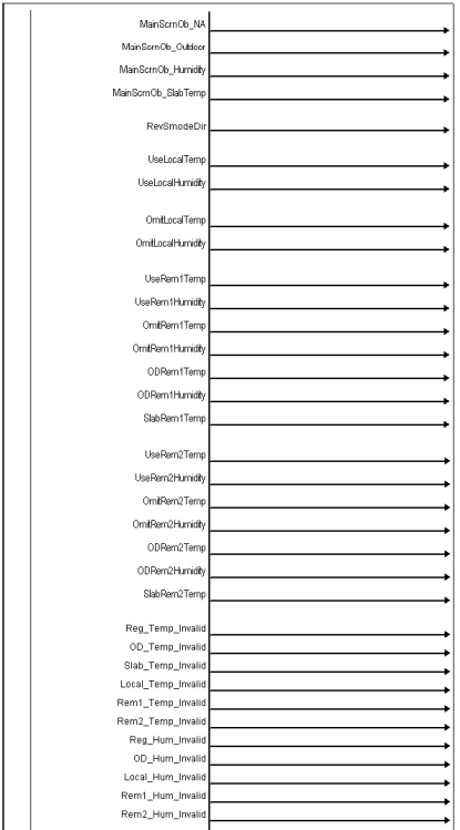
| MainScrnOb_NA MainScrnOb_Outdoor MainScrnOb_Humidity
MainScrnOb_SlabTemp |
Output | Digital | Reports the reading that will be displayed under the current temperature on the Main page of the thermostat LCD.
The “Main screen object” can be outdoor temperature, slab temperature, indoor humidity, or none (NA). |
| RevSmodeDir | Output | Digital | Reverses the direction that the selection box moves for mode screens.
High/1 = Up arrow moves box to left; Low/0 = Moves box to right |
| SIGNAL | I/O | SIGNAL TYPE | DEFINITION |
| UseLocalTemp UseLocalHumidity OmitLocalTemp OmitLocalHumidity | Output | Digital | Reports the designator assigned to the local (internal) sensors.
The CHV-TSTAT provides one internal temperature sensor; the CHV-THSTAT provides internal sensors for temperature and humidity. Each sensor must be designated as Use or Omit. Readings from local and remote sensors that have the same designator are averaged together. Thus two temperature sensors set to Use are averaged for the air temperature control, while two humidity sensors set to Use are averaged to determine the humidity. A sensor designated as “Omit” signifies that the reading will not be included in such averaging. |
| UseRem1Temp UseRem1Humidity OmitRem1Temp OmitRem1Humidity ODRem1Temp ODRem1Humidity SlabRem1Temp UseRem2Temp UseRem2Humidity OmitRem2Temp OmitRem2Humidity ODRem2Temp ODRem2Humidity
SlabRem2Temp |
Output | Digital | Reports the designator assigned to the remote sensors.
The CHV-TSTAT and CHV-THSTAT provide two remote channels. Each channel supports two sensors, for a maximum of four remote sensors. Crestron manufacturers three sensor models: CHV-RTS: temperature sensor CHV-RTHS: dual temperature/humidity sensor CHV-RSS: slab sensor Each sensor must be designated as Use, Omit, OD (Outdoor) or Slab. Readings from local and remote sensors that have the same designator are averaged together. Thus two sensors set to Use are averaged for the air temperature control, while two OD readings are averaged to determine the outdoor temperature, and two Slab readings are averaged for the floor temperature. A sensor designated as “Omit” signifies that the reading will not be included in such averaging. |
| Reg_Temp_Invalid OD_Temp_Invalid Slab_Temp_Invalid Local_Temp_Invalid Rem1_Temp_Invalid Rem2_Temp_Invalid Reg_Hum_Invalid OD_Hum_Invalid Local_Hum_Invalid Rem1_Hum_Invalid
Rem2_Hum_Invalid |
Output | Digital | These outputs show the state of the temperature or humidity measurement for their corresponding source. If the signal is high
(1) then the value on the corresponding analog output should be considered invalid. This can happen due to unconnected sensors, communications problems, or other error conditions. If the signal is low (0), the corresponding analog value is assumed to be correct. |
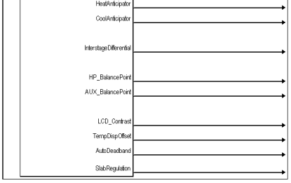
| HeatAnticipator CoolAnticipator | Output | Analog | Reports the heat and cool anticipator values, from 1 to 6. Prevents overshooting the set temperature.
A lower number signifies more frequent cycles and faster response (tighter regulation), while a higher number signifies less frequent cycles and slower response (looser regulation). |
| SIGNAL | I/O | SIGNAL TYPE | DEFINITION |
| InterstageDifferential | Output | Analog | Reports the interstage differential in tenths of a degree. This is the proportional temperature error to trigger the second (Auxiliary) stage. The scale (Fahrenheit or Celsius) is based on the current setting in the unit.
Values range from 0.5 to 8.0 (5°F to 30°F); or 0.25 to 4.5 (3° to 4.5°C). |
| HP_BalancePoint AUX_BalancePoint | Output | Analog | Reports the heat pump balance point and auxiliary balance point in tenths of a degree. The scale (Fahrenheit or Celsius) is based on the current setting in the unit.
HP values range from 0 to 890 (0 to 89˚F); 0r –180 to +310 (-18˚C to 31˚C). The heat pump balance point is the outdoor temperature below which heat pump operation is locked out, and auxiliary heat runs in place of it. The auxiliary balance point is the outdoor temperature above which auxiliary heat is locked out. Aux values range from 0 to 900 (0˚to 90˚F); or –170 to +320 (-17˚C to 32˚C). |
| LCD_Contrast | Output | Analog | Reports the LCD screen contrast.
Values range from 1 (lightest) to 10 (darkest). |
| TempDispOffset | Output | Analog | Reports the temperature offset in tenths of a degree. The offset is the number of degrees added or subtracted from the actual sensed temperature. The scale (Fahrenheit or Celsius) is based on the current setting in the unit.
Values are as follows: Fahrenheit: -60 to +60 (-6˚ to +6˚F) Celsius: -30 to +30 (-3.0˚to +3.0˚C) This temperature offset changes the actual regulated temperature, not just the displayed temperature. The offset is set to “0” as shipped from the factory. |
| AutoDeadband | Output | Analog | Reports the auto mode deadband value in tenths of a degree. The scale (Fahrenheit or Celsius) is based on the current setting in the unit.
Values are as follows: Fahrenheit: 20 to 60 (2˚ to 6˚F) Celsius: 10 to 30 (1˚ to 3˚C) Half degrees Celsius mode: 10 to 35 (1˚ to 3.5˚C) The deadband sets the minimum separation in auto mode between the heat and cool setpoints, or the changeover band in single point auto mode. |
| SlabRegulation | Output | Analog | Reports the slab temperature regulation value. Values range from 1 to 6.
A lower number signifies more frequent cycles and faster response (tighter regulation), while a higher number signifies less frequent cycles and slower response (looser regulation). |
Example Programs: The example program for the thermostat is available from the Crestron FTP site (ftp://ftp.crestron.com/Examples). Search for CHV-THSTAT_with_5-2_Scheduler_Sample_Program.zip.
Viewport ID String
Using the Diagnostics | Report Network Devices (F4) command in Viewport, the thermostats output a string of characters that describe the setup and configuration of the thermostat. Refer to the following table for an explanation of this string. A semicolon separates each element of the setup string. Strings are contained within parenthesis, and follow one space after the PPN in the ID string. Refer to the following two examples of ID strings.
Example 1
- SLAB 4B system with aux heat (SB4B-AX;)
- Slab max is 50C (SMX50;)
- Interstage differential is 2.0C (ID2.0;)
- Balance points are -10C, 0C, offset of 0C (HBP-10; ABP0; OS0.0;)
- Auto dead band 2C (ADB2.0;)
- Half C units (C05;)
2A: CHV-THSTATA [v2.0, #D8000000] (SB4B-AX;H1;C1;HA2;CA2;SMX50;ID2.0; HBP-10;ABP0;OS0.0;ADB2.0;DA;C05;OUSOOO;SETUP)
Example 2
- SLAB 1 system with slab regulation index 3 (SB1;SRG3;)
- Offset of 0C (OS0.0;)
- Half C units (C05;)
2B: CHV-THSTATA [v2.0, #D8000000] (SB1;SRG3;OS0.0;C05;OUSOOO;SETUP)
Refer to the following chart for ID string definitions.
ID Strings Description
| FUNCTION | OPTIONS | DESCRIPTION |
| System Type | H/C, HP, SB1, SB2, SB3, SB4A, SB4B, SB5A, SB5B | Heat/cool, heat pump, or slab system |
| System Type Suffix | RD FA DF
AX |
Radiant Forced Air
Heat pump with Dual Fuel Heat pump with Auxiliary |
| Heat Stages | H1, H2 | Number of heating stages, 1 or 2 |
| Cool Stages | C1, C2 | Number of cooling stages, 1 or 2 |
| Heat Anticipator | HA1 – HA6 | Heat anticipator setting, from 1-6 |
| Cool Anticipator | CA1 – CA6 | Cooling anticipator setting, from 1 – 6 |
| Slab Temperature Max | SMX | Maximum slab temperature for Slab2, Slab3, Slab4A ,and Slab4B types followed by a number (example: SMX100) |
| Regulation Index | SRG | Floor warming regulation index for Slab1, Slab3, Slab5A, and Slab5B types followed by a number (example: SRG4) |
| Interstage Differential | ID | Differential for multistage heat/cool, heat pump, Slab4A, and Slab4B types followed by a number (example: ID1.0) |
| Heat Pump Balance Point | HBP | Balance point for heat pump, Slab4B, and Slab 5B types followed by a number (example: HBP-10) |
| Aux Balance Point | ABP | Balance point for heatpump, Slab4B, and Slab5B types followed by a number (example: ABP70) |
| Offset Temperature | OS | Offset temperature display value, followed by a number from -6 to 6 degrees (Example: OS-1) |
| Auto Deadband | ADB | Minimum separation between heat and cool setpoints in auto mode, degrees, 2 – 6, for systems containing cooling only (Example: ADB3) |
| Temperature Unit | F
C10 C05 |
Fahrenheit
Celsius whole units Celsius half units |
| Sensor Usage Flags | U, D, O | Indicates the status of each sensor input: Use, outDoor, or Omit, sensor series is as follows:
Built-in-temp; built-humidity; remote 1 temp; remote1 hum; remote 2 temp; remote 2 hum. |
NOTE
- Depending on system type, not all of the ID String options listed above will be present.
- If you are in setup, the word SETUP appears in the string after the list of sensors.
- If you have restored a version 1.0 or 1.1 setup in this power cycle, an R appears after the word SETUP.
Viewport Error Log Message Formats
When a remote sensor that has been designated as USE, SLAB, or OD in the Setup Sensors screen generates an error, a message is sent to the error log. Retrieve this message using Viewport, Function | 2-Series | Error Log | Show Error Log.
Error Message Format
Sensor <channel> type <designator> <CHA errors>, <CHB errors> Errors @ <cycle count>
Where: channel is the sensor channel string designator is the sensor setup designation CHA errors/CHB errors are the number of errors on each sub-channel cycle count is the number of read cycles that have occurred.
NOTE: Both sub-channels have their error count reported, regardless of the sensors connected.
This message is sent upon the first error on the channel, as well as every 100 errors thereafter. The following is an example output, as seen in Viewport, when a single OD sensor on channel one fails.
Error: Message from device Slot-09.ID-2A: Sensor R1T type OD: 2,3 Errors @ 3922 (0056:0000:0056)
Local Error Messages
When a critical sensor fails and prevents the safe or intended operation of the HVAC equipment, an error message flashes on the main screen.
This error message appears as a text message under the line that normally reads ON LINE and VIEW MSG. The thermostat messages are shown as follows in descending priority.
| ERROR | DESCRIPTION |
| ERR! NO AT SRC | Indicates that no air temperature source is present, because all available sensors designated USE have generated errors during the current read cycle. HVAC operation is suspended and relays are cleared, except on SLAB1 type. SLAB1 type cannot generate this error because it does not have an air temperature USE type. |
| ERR! NO SB SRC | Indicates that no slab temperature source is present, because all available sensors designated SLAB have generated errors during the current read cycle. HVAC operation is suspended on all slab modes (1, 2, 3, 4A, 4B, 5A, 5B). |
| ERR! NO HM SRC | Indicates that no humidity sources are present, because all available sensors designated USE have generated errors during the current read cycle. Humidifier operation is suspended and HUM relay is cleared. |
| ERR! NO OD SRC | Indicates that no outdoor source is present and the setup says at least one remote is supposed to be providing OD data (designated OD). This error does not disable HVAC operation because it is not absolutely essential. All heatpump modes that use outdoor temperature for balance point operation will eventually stage or switch to auxiliary heat and thus prevent the space from freezing. |
Problem-Solving
Troubleshooting
The table below provides corrective action for possible trouble situations. If further assistance is required, please contact a Crestron customer service representative.
CHV-TSTAT/CHV-THSTAT Troubleshooting
| TROUBLE | POSSIBLE CAUSE(S) | CORRECTIVE ACTION |
| No display | No power from system | Check for +24V on pins 24(C) and 24(R)
Check circuit breaker powering furnace or boiler Check P4 jumper on thermostat board Check thermostat wiring |
| Incorrect mounting to backplate | Check thermostat mounting | |
| Heating/Cooling system not operating | No power to thermostat | Check circuit breaker
Check 24V connection at thermostat and at furnace/air conditioner Check circuit breaker powering furnace or boiler Recheck wiring connections |
| Flashing system indicator – Short cycle timer not satisfied | Timer Guards are a safety feature that prevents rapid switching between different cycles
H1, H2, C1, C2, SB, HM, and AX flash when the three- minute timer guards have not been satisfied Wait five minutes and/or consult HVAC contractor |
|
| Cannot change temperature setting | The upper or lower temperature limits were reached | Setpoint heat range is 38 – 90º F (3-38º C)
Setpoint cool range is 59-100º F (15 – 38º C) |
| System cycles too quickly | Anticipator/Regulation setting too low | Reprogram anticipator/regulator setting Refer to “Thermostat Setup” |
| High temperature variance | Anticipator/Regulation setting too high |
| TROUBLE | POSSIBLE CAUSE(S) | CORRECTIVE ACTION |
| Wide temperature variance in single- setpoint auto mode | Auto deadband setting too high | Adjust auto deadband setting in setup |
| Heating/Cooling not operating in single- setpoint auto mode | 20-minute system toggling lockout | Adjust auto deadband and anticipator settings for smoother operation |
| Displays Error Message and equipment not operating | Temperature sensors are disabled or have failed | Refer to “Local Error Messages” on page 84 |
| Bad communications | Check wiring – Use low capacitance twisted-pair wiring | |
| Wrong temperature displayed | Wrong units | Select F or C as necessary |
| Incorrect sensor setup | Check sensor setup | |
| Temperature Offset | Reset Temperature Offset | |
| Bad location | Ensure that thermostat is located out of direct sunlight, drafts, doorways, skylights, and windows | |
| Displays “NetDown” | No Crestron program or the program does not have a device at this net address included in this system | Check ID in program
Fix program, if one is needed |
| Cannot leave setup | Sensor configuration not valid | Ensure sensor setup meets system requirements.
Refer to Sensor Setup screen |
| Cannot enter Auto mode | Auto mode disabled in setup | Select “N” for the Disable Auto Mode item on the “Other Settings” setup page |
| Cresnet Balance Point values out of range | Values of -1, 91F represent “Off” settings | Verify intended balance point settings |
| Reports
CHV-THSTATA or CHV-TSTATA in Viewport |
Running firmware version 2.x or higher | None (name adjustment was required for SIMPL Windows) |
| Temperature offset value not affecting Cresnet outputs | Offset is only added to “RegulationTemp” | Add offset in SIMPL program |
| Cannot change screens or setpoints | Local operation locked out | Remove lockout from network |
Further Inquiries
If after reviewing this Operations and Installation Guide, you cannot locate specific information or have questions, please take advantage of Crestron’s award winning customer service team by calling:
- In the US and Canada, call Crestron’s corporate headquarters at 1- 888-CRESTRON [1-888-273-7876].
- In Europe, call Crestron International at +32-15-50-99-50.
- In Asia, call Crestron Asia at +852-2341-2016.
- In Latin America, call Crestron Latin America at +5255-5093-2160.
- In Australia and New Zealand, call Creston Pacific at +613-9480-2999
You can also log onto the online help section of the Crestron website
(www.crestron.com) to ask questions about Crestron products. First-time users will need to establish a user account to fully benefit from all available features.
Firmware Upgrades
To take advantage of all the features, it is important that the unit contains the latest firmware available. Therefore, please check Crestron’s website
(http://www.crestron.com/downloads/software_updates.asp) for the latest version of firmware. Not every product has a firmware upgrade, but as Crestron improves functions, adds new features, and extends the capabilities of its products, firmware upgrades are posted. If you have questions regarding upgrades procedures, contact Crestron customer service.
NOTE: Firmware version 2.40 is not compatible with SIMPL Windows programs that have used firmware version 1.1 and earlier.
Future Updates
As Crestron improves functions, adds new features, and extends the capabilities of this product, additional information may be made available as manual updates. These updates are solely electronic and serve as intermediary supplements prior to the release of a complete technical documentation revision.
Check the Crestron website (www.crestron.com) periodically for manual update availability and its relevance. Updates are available from the Download | Product Manuals section and are identified as an “Addendum” in the Download column.
Appendix A
Glossary
- Anticipators – Used to anticipate the drop or rise in temperature and energize the appropriate system before reaching the set point.
- Auto Dead Band Degree (Auto DdBand Deg) – Sets the minimum separation in auto mode between the heat and cool setpoints, or the changeover band in 1-point auto mode.
- Balance Point – The lowest outdoor temperature at which the refrigeration cycle of a heat pump will supply the heating requirements without the aid of a supplementary heat source.
- Blower (Fan) – An air-handling device for moving air in a distribution system.
- BTU – British Thermal Unit – In scientific terms, it represents the amount of energy required to raise one pound of water one degree Fahrenheit. One BTU is the equivalent of the heat given off by a single wooden kitchen match.
- Call – A call is when the thermostat requests the heating or cooling system to turn on.
- Damper – Found in ductwork, this movable plate opens and closes to control airflow. Dampers are used effectively in zoning to regulate airflow to certain rooms.
- Dead Band – The minimal differential between Heating and Cooling.
- Dual Fuel – A heat pump used in conjunction with an existing furnace.
- Dual Setpoint Auto – Enables the two-point auto mode.
- Emergency Heat (Supplementary Electric Heat) – The auxiliary (AUX) or emergency heat provided at temperatures below a heat pump’s balance point. It is usually electrical resistance heat.
- Forced Air – A type of heating system that uses a blower motor to move air through the furnace and into the ductwork.
- Furnace – Equipment used to convert heating energy, such as fuel, oil, gas or electricity, to usable heat. It usually contains a heat exchanger, a blower and the controls to operate the system.
- Heat Exchanger – A device for the transfer of heat energy from the source to the conveying medium of air or water. Most common combinations are: Refrigerant to air or Refrigerant to water (DX), Water to air (hydronic), Steam to air, Steam to water.
- Heat Pump – A unit that both cools and heats. A heat pump system can be either a split system or a packaged system. A heat pump can be used in conjunction with a gas/oil/LP furnace (using the furnace instead of electric resistance heat when temperatures fall below about 35º F).
- Humidity – The total amount of moisture in air. Relative humidity (RH) is the amount of moisture in air, relative to its total capability based upon its temperature (dewpoint). Moisture will condense on surfaces that are below this dewpoint.
- HVAC – Heating, ventilation and air conditioning.
- Interstage Differential – The proportional temperature error (0.5 to 3.0º) to trigger the second stage (2-stage only).
- Main Screen Lower Object (Main Screen Lwr Obj) – Selects the data item displayed at the bottom of the main screen. Choice of: none, slab temperature, outdoor temperature, or indoor humidity.
Run Fan in Heat Calls (Run Fan in Ht Calls) –A device setting that activates the fan output with W1/W2 heat calls. Does not enable operation on slab systems on the slab (W1) call. - Setpoint – The thermostat temperature set to begin heating or cooling.
- Time Delay (Timer Guards) – Refers to a safety device or circuit that will not allow restart for three minutes.
- Two Stage Heating –The heating unit starts out running in its first stage, and operates at a fraction of its capacity. When the temperature outside goes very low, the system adjusts to full capacity (second stage) to meet the demand.
- Wide Range Cool – Extends the cool setpoint range to the full auto range of 38 to 99°F.
Appendix B
About Heat Pumps
A heat pump extracts available heat from one area and transfers it to another. Even cold air contains some heat, and heat pumps can extract heat from the outside air on a cold day and transfer it indoors to maintain a comfortable temperature. A heat pump also works in reverse during the summer, extracting heat from indoors and transferring it outdoors.
In the heating mode, the efficiency of a heat pump decreases as the outdoor air temperature decreases.
- Heat Pump Operation
Heat flows naturally from a warm area to a cooler area, and the heat pump takes advantage of this principle. The heat pump essentially consists of a compressor, an inside coil and fan, and an outside coil and fan. A refrigerant flows inside the coils, under pressure applied by the compressor.
The refrigerant boils at a very low temperature (as low as -15° F) and becomes a vapor, just as water becomes a vapor (steam) when boiled. This vapor is sucked into the compressor where it becomes a high pressure, high temperature vapor.
When heating, the refrigerant is then forced through a coil within part of the heat pump located indoors. A fan blows cool air over the coil, the vapor cools, turns back to a liquid, releasing heat that is blown through a duct system to heat the house.
The cycle begins again as the cooled liquid refrigerant is pumped back outside after releasing it’s heat. On the way, it passes through an expansion valve, lowering the refrigerant’s pressure and temperature again so it can boil more easily in the outdoor coil.
- In its cooling mode the heat pump system works in reverse, extracting available heat from indoors and transferring it outside.
- Heat pumps are most economical when they can be used year-round for both winter heating and summer cooling.
The efficiency of a heat pump varies significantly with the outdoor temperature. While a heat pump may be twice as efficient as a conventional heating system at 50°F. When the outdoor temperature drops to less than 30°F, the heat pump must be supplemented with an auxiliary heating system such as electric resistance. At temperatures of 15°F or less the heat pump may shut off and the backup heating system takes over. This is the heat pump balance point. In a dual-fuel system, the heat pump is supplemented with a standard furnace, which takes over when it becomes more efficient than the heat pump at very low temperatures.
Return and Warranty Policies
Merchandise Returns / Repair Service
- No merchandise may be returned for credit, exchange, or service without prior authorization from CRESTRON. To obtain warranty service for CRESTRON products, contact the factory and request an RMA (Return Merchandise Authorization) number. Enclose a note specifying the nature of the problem, name and phone number of contact person, RMA number, and return address.
- Products may be returned for credit, exchange, or service with a CRESTRON Return Merchandise Authorization (RMA) number. Authorized returns must be shipped freight prepaid to CRESTRON, 6 Volvo Drive, Rockleigh, N.J. 07647, or its authorized subsidiaries, with RMA number clearly marked on the outside of all cartons. Shipments arriving freight collect or without an RMA number shall be subject to refusal. CRESTRON reserves the right in its sole and absolute discretion to charge a 15% restocking fee, plus shipping costs, on any products returned with an RMA.
- Return freight charges following repair of items under warranty shall be paid by CRESTRON, shipping by standard ground carrier. In the event repairs are found to be non-warranty, return freight costs shall be paid by the purchaser.
CRESTRON Limited Warranty
CRESTRON ELECTRONICS, Inc. warrants its products to be free from manufacturing defects in materials and workmanship under normal use for a period of three (3) years from the date of purchase from CRESTRON, with the following exceptions: disk drives and any other moving or rotating mechanical parts, pan/tilt heads and power supplies are covered for a period of one (1) year; touchscreen display and overlay components are covered for 90 days; batteries and incandescent lamps are not covered.
This warranty extends to products purchased directly from CRESTRON or an authorized CRESTRON dealer. Purchasers should inquire of the dealer regarding the nature and extent of the dealer’s warranty, if any.
CRESTRON shall not be liable to honor the terms of this warranty if the product has been used in any application other than that for which it was intended, or if it has been subjected to misuse, accidental damage, modification, or improper installation procedures. Furthermore, this warranty does not cover any product that has had the serial number altered, defaced, or removed.
This warranty shall be the sole and exclusive remedy to the original purchaser. In no event shall CRESTRON be liable for incidental or consequential damages of any kind (property or economic damages inclusive) arising from the sale or use of this equipment. CRESTRON is not liable for any claim made by a third party or made by the purchaser for a third party.
CRESTRON shall, at its option, repair or replace any product found defective, without charge for parts or labor. Repaired or replaced equipment and parts supplied under this warranty shall be covered only by the unexpired portion of the warranty.
Except as expressly set forth in this warranty, CRESTRON makes no other warranties, expressed or implied, nor authorizes any other party to offer any warranty, including any implied warranties of merchantability or fitness for a particular purpose. Any implied warranties that may be imposed by law are limited to the terms of this limited warranty. This warranty statement supercedes all previous warranties.
Trademark Information
All brand names, product names, and trademarks are the sole property of their respective owners. Windows is a registered trademark of Microsoft Corporation. Windows95/98/Me/XP and WindowsNT/2000 are trademarks of Microsoft Corporation.
Operations and Installation Guide – DOC. 8163C 08.04
Specifications subject to change without notice.
Crestron Electronics, Inc.
- Address: 15 Volvo Drive Rockleigh, NJ 07647
- Tel: 888.CRESTRON
- Fax: 201.767.7576
- www.crestron.com
Reference
Download Manual:
Crestron CHV-THSTAT Wireless Programmable Thermostat Operations Guide
Other Manual:
Crestron CHV-THSTAT Wireless Programmable Thermostat Product Specification Guide
Crestron CHV-THSTAT Wireless Programmable Thermostat Operations Guide
Leave a Reply