
Center 340009 RF Thermostat
Introduction
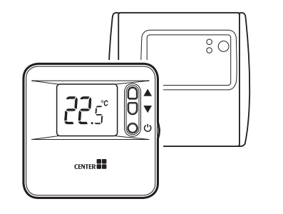
340009 is an RF thermostat. The Room Unit communicates with the relay Box on an 868MHz Radio Frequency (RF) to control a single heating system components such as a boiler, pump or zone valve. Neither product will communicate with other RF products that use different frequencies or communication protocols.
Note: The RF link between the Room Unit and Relay Box is pre-configured at the factory so these units should be installed together at the same site. If the units become separated or one of them needs to be replaced, they will need to be bound together – see Binding or Re-Binding Procedure.
Specification
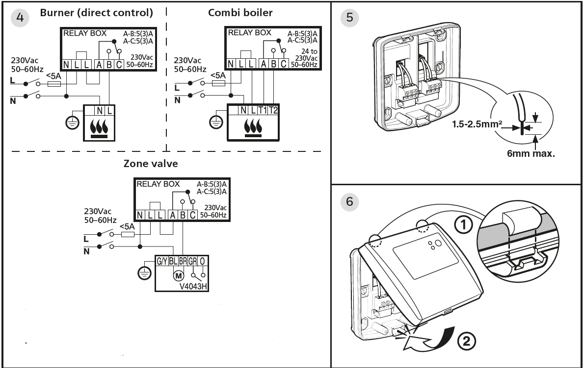
- Power Supply: 230Vac, 50–60 Hz (Relay Box)
2 x AA Alkaline batteries (Room Unit) - Switch Rating: SPDT, 24 to 230Vac, 50–60 Hz, 5(3)A
Hereby, Wolseley declares that this thermostat complies with the essential requirements and other relevant provisions of Directive R.E.D.: 2014/53/EU. Receiver Category 2. Max RF power: 25mW.
Operating frequency: 868.3MHz (868.0 to 868.6MHz).
The full text of the EU Declaration of Conformity is available at the following Internet addresses:
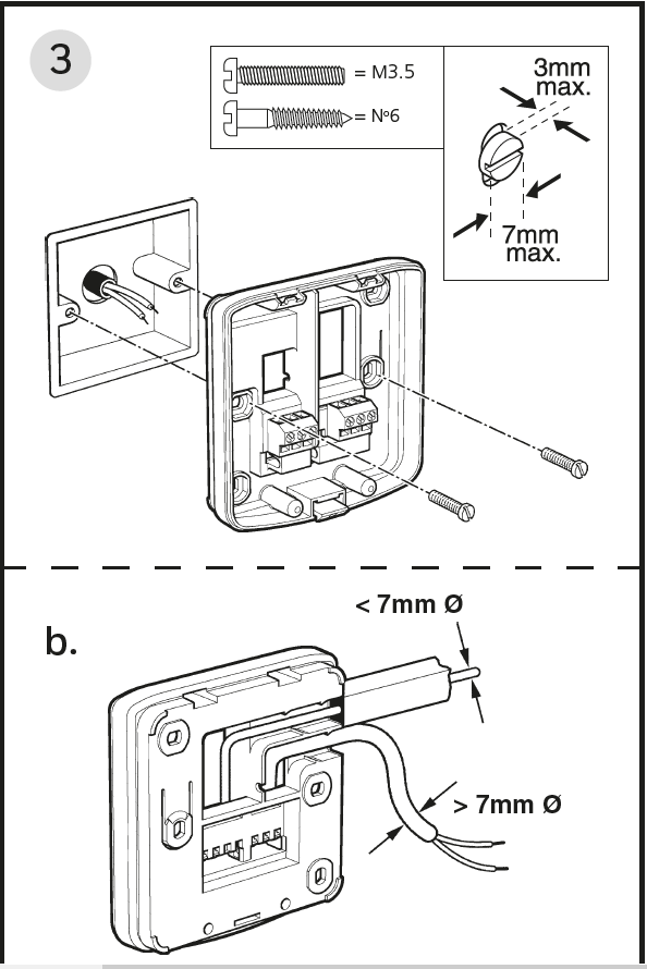
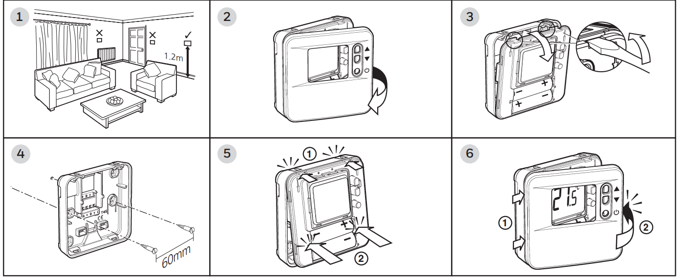
Installing the Relay Box
- The Relay Box is an RF device. For the best performance install in an open space. Leave at least 30cm distance from any metal objects including wall boxes and boiler housing.
Do not mount on metal wall boxes.
EMC compliance considerations Keep AC mains supply/load cables separate from signal wiring.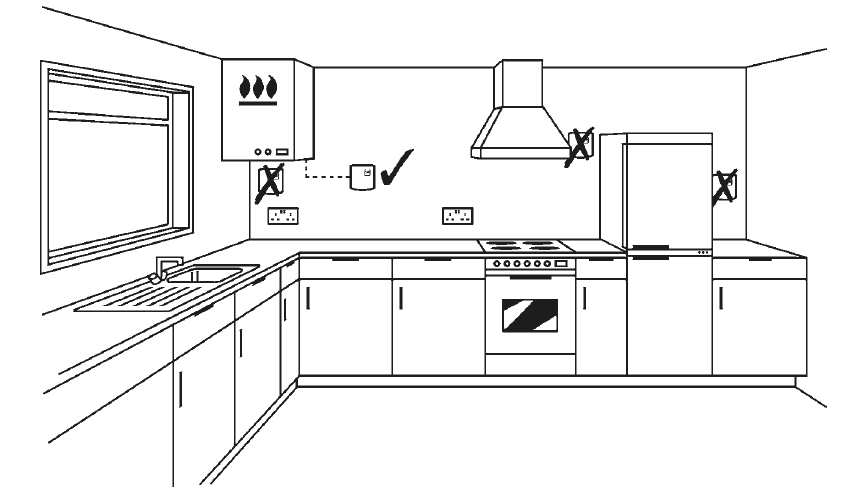
- NOTE: The Relay Box contains no user-serviceable parts. It should be opened and installed by a qualified installer only.
WARNING: Electrostatic sensitive device! Do not touch the circuit board.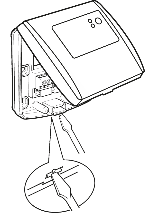
-
Testing the Thermostat RF Connection
- Apply mains electrical power to the Relay Box
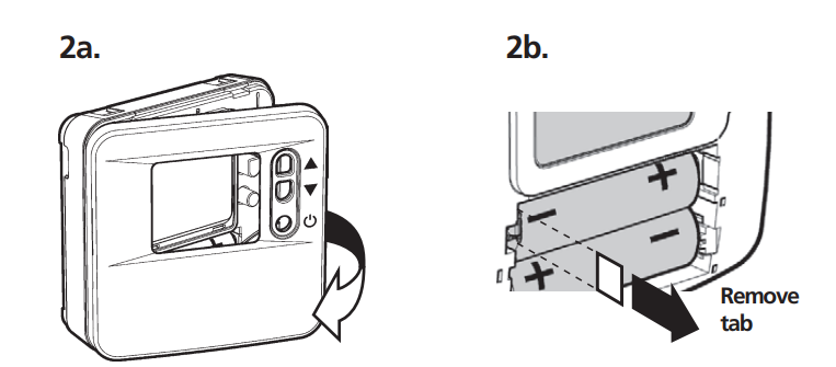
- Power up the Room Unit
- Remove the cover
- Remove and discard the plastic tab inside the battery compartment, illuminating the display
- Hold the Room Unit 2-3 metres from the Relay Box
 Put the Room Unit into TEST Mode
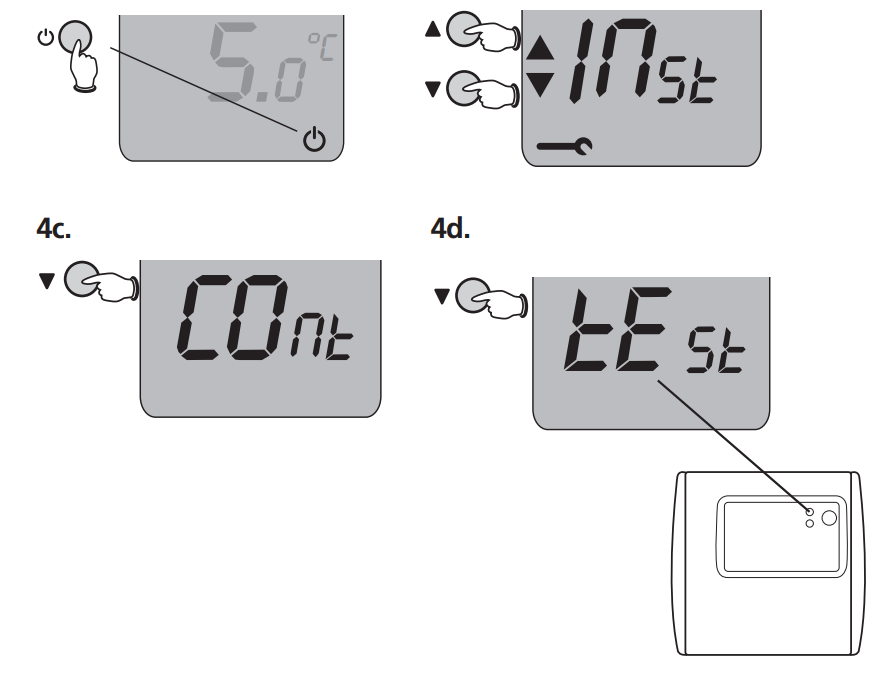
- Press and hold the
 button for 2 seconds
 - Press and hold the
 and
and  buttons together until the screen changes as shown
 - Press thebutton once
- Press and hold thebutton until the screen displays tEst. If the green light on the Relay Box does not flash periodically, the units are not Bound together. See Binding or Re-Binding Procedure to re-establish wireless communication
- Next test the signal strength to find
- Suitable location for the Room Unit installation
Testing the RF Signal Strength
- Press and hold the
- While still in TEST mode:
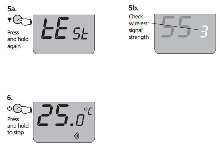
- Press and hold the button to enter SIGNAL STRENGTH Mode
- The display will show SS and a number from 0 to 5 indicating signal strength. This number will reset to zero every few seconds as a new signal measurement is made
- Strength 0, 1, 2 = POOR SIGNAL => move Room Unit to a better location Strength 3, 4, 5 = GOOD SIGNAL => ok to install Room Unit in this location
- Press and hold the
- Press and hold the button to end the test
Installing the Room Unit
Install where signal strength is good, at least 30cm from any metal objects and at least
1m away from other electrical devices. Avoid proximity to heat sources or draughts.
Installer Setup (allows Thermostat to be configured for the application)
- Enter Installer Setup Mode

- Press and hold thebutton for 2 seconds
- Press and hold the and buttons together until the screen displays INst
- Pressbutton once to show first parameter
- Press and hold the
- Use the and buttons to scroll around all the available parameters
- To change any setting, press the button, then press the and buttons until the correct value is flashing
- Press to save the selection, then use the and buttons to select another parameter
- To Exit Installer Setup, press and hold for 3 seconds
| Parameter | Description | Default Value | Setting options |
| Ot | Minimum boiler on/off time | 1 minute | 1 to 5 minutes |
| Cr | Boiler cycles per hour | 6 cycles per hour | 3, 6, 9, 12 cycles |
| Pb | Proportional Band Width | 1.5°C | 1.5 to 3.0°C |
| tO | Temperature Offset | 0 = no offset | +3 to -3°C |
| uL | Maximum set temperature limit | 35°C | 21 to 35°C |
| LL | Minimum set temperature limit | 5°C | 5 to 21°C |
| HC | Heating/ Cooling changeover enable | 0 = no changeover | 1 = changeover allowed* |
| OS | Frost Protection temperature | 5°C | 5 to 16°C |
| LC | Loss of Communications instruction | 0 = switch off | 0 or 1 = operate 20% on |
| FS | RESET to factory defaults | 0 = no change | 1 = restore factory settings |
* To change from Heating to Cooling Mode, press and hold both![]() and
and ![]() buttons together for 3 seconds
buttons together for 3 seconds
Binding or Re-Binding Procedure
Only Bind or Re-Bind if the units become separated or one of them needs replaced.
No need to re-connect after power cuts or battery replacement.
- Put the Relay Box into Binding Mode
- Press and hold the Relay Box button for 15 seconds to cancel any prior Binding information
- After releasing the button, hold it down again for 5 seconds until the red light flashes evenly
- Put the Room Unit into Binding Mode
- Press and hold thebutton for 2 seconds, then hold the and buttons together until the screen displays Inst
- Press the button so the screen displays COnt
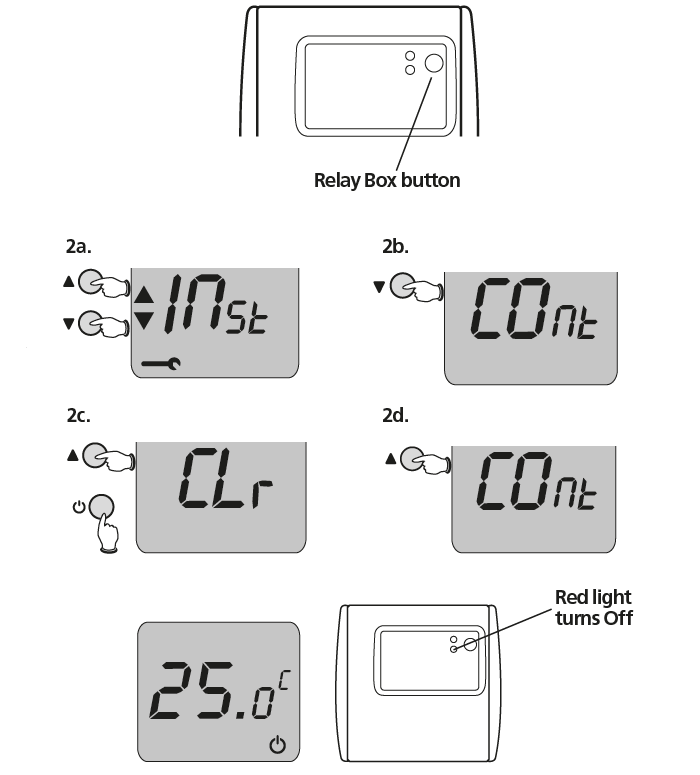
- Press thebutton repeatedly until the screen displays CLr. Then press to clear any previous binding to other devices
- Press the button again to return to Binding Mode, where the screen displays COnt
- Press and hold the
- Press the button to send the Binding signal to the Relay Box. If successful, the red light on the Relay Box will stop flashing and turn off.
In a few seconds the Room Unit will return to normal operation, in Standby mode
For further information telephone 0344 292 7062
Whilst every care has been taken to ensure that the information included in this document was accurate at the time of printing, we reserve the right to change specifications at any time.
The photographs reproduced in this publication are within the constraints of the printing process and are NOT to be used for matching purposes. E&OE.
Wolseley UK, The Wolseley Center, Harrison Way, Spa Park, Royal Leamington Spa, CV31 3HH
WEEE Directive 2012/19/EU
At the end of the product life dispose of the packaging and product in a corresponding recycling centre.
Do not dispose of the unit with the usual domestic refuse. Do not burn the product.
REFERENCE:
DOWNLOAD MANUALAS
Center 340009 RF Thermostat Installation Guide
![]()
Leave a Reply