
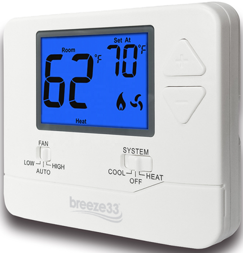
Breeze33 BZ33-201NW Non-Programmable Wireless Thermosta
Installation
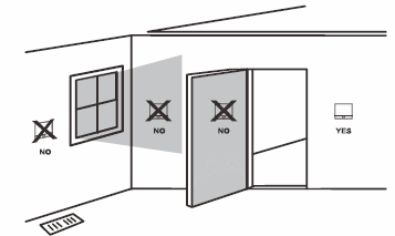
Wall Locations
The thermostat should be installed approximately 4 to 5 feet above the floor. Select an area with average temperature and good air circulation
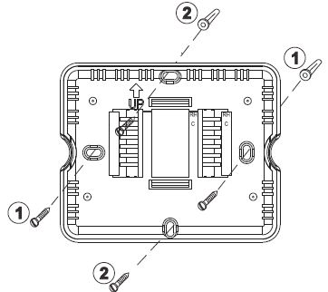
Subbase Installation
- Horizontal Mount
- Vertical Mount
Power Type
- Battery Power
- Hardwire (Common Wire)
- Hardwire (Common Wire) with
- Battery Backup
Mount Thermostat
Align the 4 tabs on the sub-base with corresponding slots on the back of the thermostat, then push gently until the thermostat snaps in place .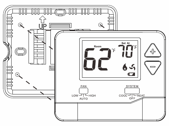
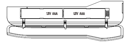
Battery Installation
Battery installation Is optional If the thermostat ls hardwired (Rand C terminal connected to 24V power.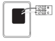
Important: High-quality alkaline batteries are recommended. Rechargeable batteries or low-quality batteries do not guarantee a 1-year life span.
lnsert2 AAA Alkaline batteries (included. High-quality alkaline tiatter1es are recommended
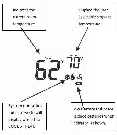
Getting to know your thermostat
- LCD
- Fan Switch
- System Switch
- Setpoint Buttons
Wiring
- If you are replacing a thermostat, make note of the terminal connections on the thermostat that is being replaced. In some cases the wiring connections will not be color coded. For example, the red wire may not be connected to the R terminal.
- Loosen the terminal block screws. Insert wires then retighten terminal block screws.
| Transformer power
{cooling) |
Transformer power | Transformer power | ||
| R | (cooling) | (cooling) | ||
| C |
Transformer common |
Transformer common | Transformer common | |
| B |
Energized in heating |
Heat pump changeover valve energized in cooling | Heat pump changeover valve energized in heating | |
| 0 |
Energized in cooling |
Heat pump changeover valve energized in cooling | Heat pump changeover valve energized in cooling | |
| GL |
Fan Relay, Low |
Fan Relay, Low | Fan Relay, Low | |
| GH |
Fan Relay, High |
Fan Relay, High | Fan Relay, High | |
| w |
First stage of heat |
N/A |
Second stage of heat |
|
| y |
First stage of cool |
First stage of heat & cool | First stage of heat & cool |
Wiring Tips
CTerminal
The C (common wire) terminal does not have to be connected when the thermostat is powered by batteries .
Wire Specifications
Use shielded or non-shielded 18-22 gauge thermostat wire.
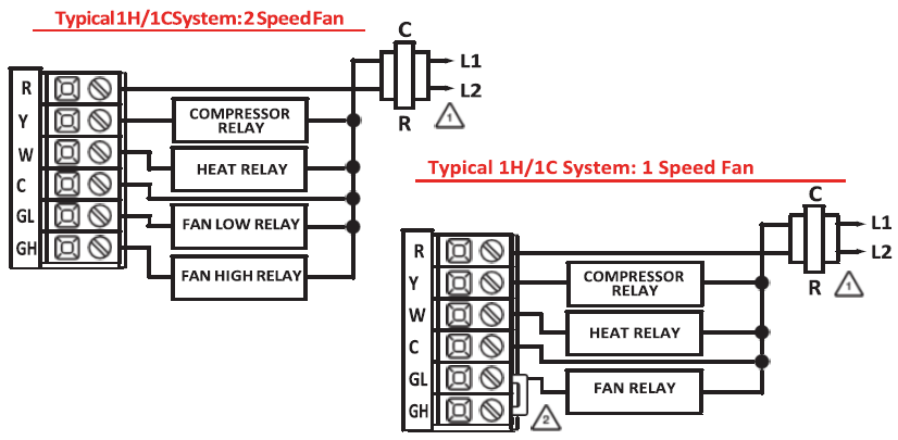
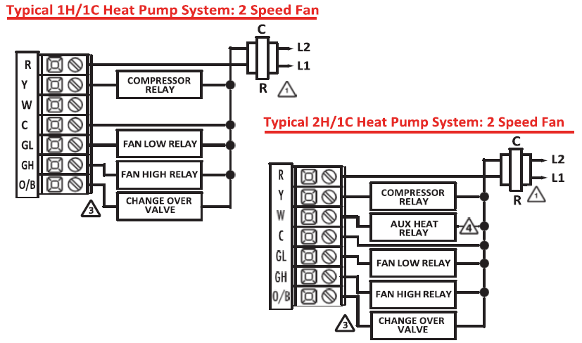
Wiring Diagrams
- Power supply
- Jumper (not supplied) to connect GL and GH terminals.
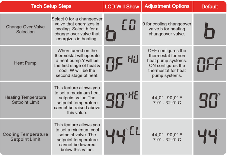
- The thermostat must be set to 0 and B to match the changeover valve, O is the cool changeover valve, B is the heat changeover valve
- The Aux Heat Relay Is energized as the second stage of heat.
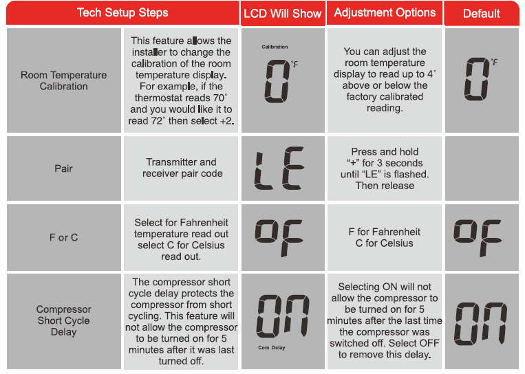
Technician Setup
Fan OperatlonSetup
Electric: The thermostat operation jumper pin should be put in the ELEC position. This setting allows the thermostat to operate the fan during a call for heat. Most PTAC systems will require ELEC Fan Operation Setup.
Gas: For systems that control the fan during a call for heat, put the jumper pin into the GAS position.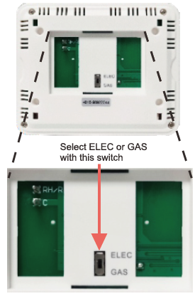
Menu
- Set the thermostat system switch ID OFF.
- To enter the tech setup Menu, press and hold ‘+” and ‘-“together for 3 seconds.
- Use ‘+’and’-‘to to select the desired setting for each option.
- Tap ‘+’and “-‘ together to move the next option.
- To exit Tech Setup Menu. move the system switch or wait for 15 seconds
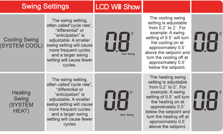
Swing Setting
- Set the thermostat system switch to the desired position (COOL or HEAT).
- Press and hold “+”and “-“togetherfor3 seconds.
- Use “+” and “-” to adjust desired swing setting (The display reads in tenths of a degree.)
- To exit, move the system switch or wait for 1 second
The second stage of Heat will turn on at 2x the swing setting. The second stage will turn off when 1 x the swing is reached. For example, if the swing setting is 0.8° for heating and the thermostat is set at 70″ F, the first stage will turn on at approximately 69.2″ F. The second stage will turn on at 68.4″F and the first will turn off at 70.8″ F.
RF Pairing
- Receiver: Use a slender object into the hole and keep it depressed (for approximately 5 seconds) until the red LED starts flashing.
- Transmitter: Turn the SYSTEM switch to OFF. Press and hold”+” and “-” together for 3 seconds to access the interface of room temperature calibration. Press and hold”+” and “-” together until”LE” is displayed on the LCD.Then press and hold “+” for 3 seconds , the transmitter will transmit the code signal. When the red LED on the receiver stops flashing, indicating that the code is successful.
Specifications
- The display range of temperature … 32’F to 99’F (l’C to 40″C)
- The control range of temperature …. 44’F to 90″F (7’C to 32’C)
- Load rating ……………………………………. 1 amp per terminal, 1.5 amp maximum all terminals combined
- Swing (cycle rate or differential) …… Heating is adjustable from 0.2• to 2.0″
- Cooling is adjustable from 0.2• to 2.0″
- Power source ……………………………….. 18 to 30 VAC, NEC Class II, 50/60 Hz for hardwire
- Battery power from 2 AAA Alkaline batteries
- Operating ambient …………………….. 32’F to +105’F (O”C to +4l’C)
- Operating humidity …………………….. 90% non-condensing maximum
- Dimensions of thermostat …………….. 120 x 98 x 28M M
- Operating Frequency ………………………. 433.92MHz
WARRANTY
Breeze33 Products LLC (Breeze33) warrants to the ORIGINAL PURCHASER that its thermostats shall be free from defects in material and workmanship under normal use and service for a five (5) years. This warranty cannot be transferred – it is extended only to the original Purchaser or First User of the Product. By accepting and keeping this Product you agree to all of the warranty terms and limitations of liability described below. Breeze33ʼs obligations under the warranty set forth above shall be to replace any Breeze33 Thermostat which is defective
WHAT IS NOT COVERED?
The warranty above does not cover and Breeze33 is not liable for, (i) installation, (ii) any labor charges or (iii) products which have been damaged as a result of any accident, misuse, abuse, neglect, improper installation or maintenance, the use of abrasive or organic solvent cleaners, modification, failure to use the register, grille, or diffuser in accordance with instructions provided by Breeze33
HOW TO OBTAIN WARRANTY SERVICE Contact our warranty department at 740-314-4404 to report the defect. Return failed product with proof of purchase,your name, and address within 30 days of failure to
- Breeze33 Products LLC 350
- Courtney Road Sebring,
- Ohio 44672 USA
LIMITATION OF LIABILITY WARRANTY
Breeze33ʼs liability on any claim of any kind, including, without limitation, warranty, negligence and/or breach of contract, shall in no case exceed the purchase price paid by the Customer. IN NO EVENT SHALL BREEZE33 BE LIABLE FOR ANY SPECIAL, INCIDENTAL, CONSEQUENTIAL (INCLUDING, WITHOUT LIMITATION, DAMAGE TO PROPERTY) OR PUNITIVE DAMAGES, DAMAGES IN THE NATURE OF PENALTIES, OR SIMILAR OR RELATED DAMAGES OF ANY KIND.
DISCLAIMER OF WARRANTIES
BREEZE33 EXPRESSLY DISCLAIMS ALL WARRANTIES, EXCEPT AS EXPLICITLY STATED HEREIN, TO THE FULLEST EXTENT PERMITTED BY LAW, WHETHER WRITTEN, ORAL, EXPRESS OR IMPLIED, INCLUDING ANY WARRANTY OF PERFORMANCE, MERCHANTABILITY, FITNESS FOR A PARTICULAR PURPOSE, AND NONINFRINGEMENT. THIS DISCLAIMER INCLUDES ANY ORAL WARRANTIES OR REPRESENTATIONS MADE OR IMPLIED BY ANY AGENT, EMPLOYEE, SUBCONTRACTOR, MANAGER, DIRECTOR AND/OR REPRESENTATIVE OF BREEZE33.
REFERENCE:
DOWNLOAD MANUALS:
Breeze33 BZ33-201NW Non-Programmable Wireless Thermostat Installational Manual
![]()
Breeze33 BZ33-201NW Non-Programmable Wireless Thermostat Installational Manual
Leave a Reply