
bnthermic B16C PROGRAMMABLE ROOM THERMOSTAT
Model: B16C
Thank you for purchasing a BN Thermic product. Manufactured to a high standard, this product will, if used according to these instructions and properly maintained, give you years of trouble free performance. Please ensure instructions remain with your customer for their reference.
REGISTER: PLEASE REGISTER THIS PRODUCT ONLINE TO ACTIVATE YOUR GUARANTEE AT www.bnthermic.co.uk
IMPORTANT: PLEASE READ THESE INSTRUCTIONS, NOTE THE SAFE OPERATIONAL REQUIREMENTS, WARNINGS, AND CAUTIONS. USE THIS PRODUCT CORRECTLY, AND WITH CARE FOR THE PURPOSE FOR WHICH IT IS INTENDED. FAILURE TO DO SO MAY CAUSE DAMAGE AND/OR PERSONAL INJURY AND WILL INVALIDATE THE WARRANTY.
SECTION A – USER INSTRUCTIONS.
- For installation instructions.
INTRODUCTION & SPECIFICATION
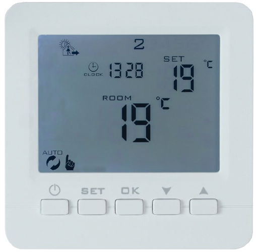
The B16C Thermostat is an easy to install and use 7 Day, 6/1 Day or 5/2 Day Programmable Room Thermostat which offers four time and temperature changes each day. It is designed to provide automatic time and temperature control for underfloor heating using air temperature and a floor sensor. All settings are stored in the controller with battery back-up.
| B16C- Programmable Heater Controller | |
| Programming | 7 Day, 6+1 Day or 5+2 Day (Default 5+2 Day) |
| Power Supply | 230V ac 50 Hz 16A Maximum Load (Battery back-up) |
| Floor Temperature Sensor | NTC (10KΩ) +/- 0.5°C at 20°C |
| Temperature Range | 1°C to 45°C (Default 5°C to 30°C) |
| Display | LCD + back light that comes on for short period when any button pressed. |
| Number of Programs Per Day | 4 |
| Tamper Resistant | Facility for locking all buttons or just temperature adjustment buttons. |
| Dimensions | 86mm x 86mm x 15mm deep when recessed. Fits standard recess boxes. |
| Electrical Protection | Class II IP20 |
|
Complies with: |
EN 301489-1, EMC Directive 2014/30/EU, EN60950-1:2006+a11:2009+a1:2010+a12:2011+ a2:2013 |
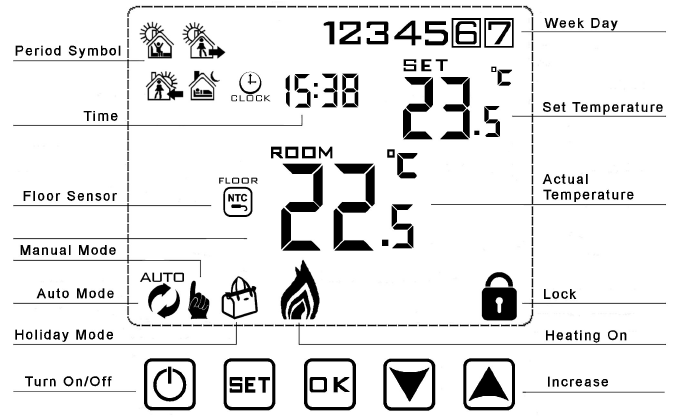
OPERATING GUIDE
To Set Time and Week Day Number
- Turn thermostat on by pressing
 button.
Press the ok button and the minutes will start to flash. Adjust the minutes by pressing the or
or  buttons. When correct, press ok button and the hours will flash. Set these by pressing the or buttons. When correct, press ok button and the day number will flash. Set this by pressing the or buttons. When correct, press ok. Note that Monday is 1, Tuesday 2 etc. If you don’t press a button for 5 seconds display returns to standard mode and you will need to repeat section b.
Programming: The controller is preset to the following times and temperatures:
| Period | ||||||||
|
Day Number |
Wake up |
Outdoor |
Back home |
Sleep |
||||
| 1 | 06:00 | 20⁰C | 08:00 | 15⁰C | 17:00 | 20⁰C | 22:00 | 15⁰C |
| 2 | 06:00 | 20⁰C | 08:00 | 15⁰C | 17:00 | 20⁰C | 22:00 | 15⁰C |
| 3 | 06:00 | 20⁰C | 08:00 | 15⁰C | 17:00 | 20⁰C | 22:00 | 15⁰C |
| 4 | 06:00 | 20⁰C | 08:00 | 15⁰C | 17:00 | 20⁰C | 22:00 | 15⁰C |
| 5 | 06:00 | 20⁰C | 08:00 | 15⁰C | 17:00 | 20⁰C | 22:00 | 15⁰C |
| 6 | 08:00 | 20⁰C | 10:00 | 15⁰C | 16:00 | 20⁰C | 23:00 | 15⁰C |
| 7 | 08:00 | 20⁰C | 10:00 | 15⁰C | 16:00 | 20⁰C | 23:00 | 15⁰C |


By default the controller is set to 5+2 days this means when programming Monday – Friday settings will all be the same and you can then program different settings for Saturday – Sunday. If you require 7 day or 6+1 day settings enter defeult settings and adjust paramenters first (See section 5).
To adjust or program the time & temperature periods
- Make sure the thermostat is on, or turn on by pressing button.
- Press and hold the
 button for 3-5 seconds until the time starts to flash, display will also show “12345”and the first period symbol will show. Adjust the hours by pressing the or buttons. When correct, press the button and the minutes will flash. Set these by pressing the or buttons. When correct, press button and the temperature will flash. Set this by pressing the or buttons. When correct, press and the second period symbol will show and the hours will flash. Now repeat the above to set all 4 periods. Once set, the days will change to 6+7 and you repeat the above procedure to program Saturday and Sunday. Note “12345” on the display while programming means you are setting all 5 Weekdays “6+7” on the display while setting means you are programming Saturday & Sunday. If you don’t press a button for appox 5 seconds the controller will automatically store the settings and exit programming mode.
Run Modes
- Turn thermostat On or Off by pressing the button.
- When “ON” press to toggle between Auto mode
 and Manual mode
 .
. - When in Auto mode you can override the set tempreture by pressing the or buttons. This override will last until the next program period and is shown by both the and symbols.
- When in Manual mode you can override the set tempreture by pressing the or buttons.
Note
- The thermostat will stay in Manual mode with the same set temprature until you switch it to Auto mode or turn the thermostat off.
- At any time you can return to the auto temperature set point by pressing the button until only the Auto mode shows.
All Modes
- To view the floor sensor temperature (if pressent) press and hold the button for about 3 seconds, the display will change and show the reading, when you release the button the display will revert back to showing the air temprature.
Locking the controller
The controller has 2 lock settings selected in the default settings (see section 5). Half lock, when set only allows the On / Off ![]() button to be pressed. Full lock disables all buttons except the unlock sequence. Putting the controller in lock mode indicated by a
button to be pressed. Full lock disables all buttons except the unlock sequence. Putting the controller in lock mode indicated by a![]() symbol on the screen is done by pressing and holding the
symbol on the screen is done by pressing and holding the![]() button until the
button until the![]() symbol appears. Unlocking is the reverse process.
symbol appears. Unlocking is the reverse process.
Holiday Mode
Holiday days (count down) and temprature set point can be set so that the heating runs at a lower temperature whilst you are away and reverts back to normal when you return. To access, make sure the controller is on and then press ok the button for 3-5 seconds until the screen displays Off change to On by using the![]() or
or![]() buttons. Then press ok the button to set the number of days you are away. Then press ok the button to set the temperature required while you are away. Holiday mode is shown by a
buttons. Then press ok the button to set the number of days you are away. Then press ok the button to set the temperature required while you are away. Holiday mode is shown by a![]() symbol displayed on the screen. Once set, to exit holiday mode early press the
symbol displayed on the screen. Once set, to exit holiday mode early press the![]() button.
button.
INSTALLATION SAFETY INSTRUCTIONS
ELECTRICAL SAFETY
WARNING: It is the responsibility of the owner and the installer to read, understand and comply with the following:
You must check all electrical products, before use, to ensure that they are safe. You must inspect power cables, plugs, sockets and any other connectors for wear or damage. You must ensure that the risk of electric shock is minimised by the installation of appropriate safety devices. A Residual Current Circuit Breaker (RCCB) should be incorporated in the main distribution board. If in any doubt consult a qualified electrician.
You must also read and understand the following instructions concerning electrical safety.
- The Health & Safety at Work Act 1974 makes owners of electrical appliances responsible for the safe condition of those appliances and the safety of the appliance operators. If in any doubt about electrical safety, contact a qualified electrician.
- Installation should always be carried out by a qualified electrician or a competent person in accordance with current electrical regulation.
- Ensure that the cables are always protected against short circuit and overload.
- The unit should be protected by a suitably rated isolator and fuse or MCB.
- This controller is IP20 rated and is suitable for indoor or under cover use only.
GENERAL SAFETY INSTRUCTIONS
- Remove all packaging and store it away from children, check the package and controller for visible damage or tampering.
- Familiarise yourself with the applications and limitations of the controller.
- Only use recommended attachments and parts. To use unauthorised parts may be dangerous and will invalidate your warranty.
- DO NOT use in areas where hazardous gasses or dusts may be present.
- DO NOT disassemble the controller for any reason. There are no user serviceable parts inside.
- DO NOT use this controller to perform a task for which it has not been designed.
Please leave the user instructions with the end user where they should be kept in a safe place for further reference.
INSTALLATION
CHOOSING A LOCATION FOR YOUR B16C
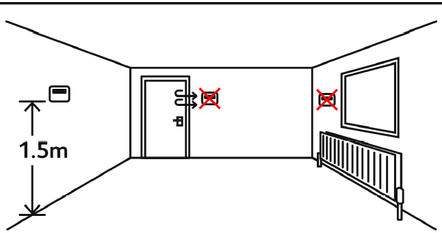
- The B16C controller should be mounted on an internal wall approximately 1.5 meters from floor level and should be in a position away from draughts, direct heat and sunlight.
INSTALLING THE B16C
- The thermostat requires a one gang back box having a minimum depth of 35mm.
- Remove the front screen from the thermostat by gently using a screwdriver underneath the front lip to release the two plastic clips. Gently pull the screen towards you releasing the internal plug which allows the two parts to be separated.
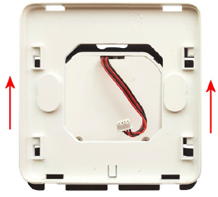
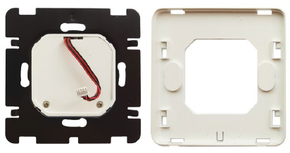
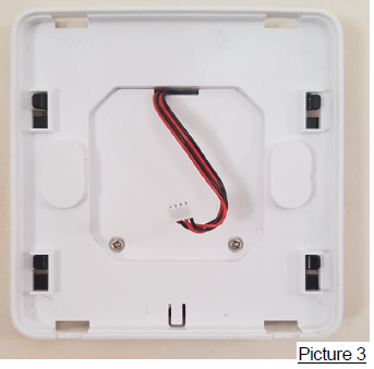
- Now remove the plastic centre housing from the back plate by gently lifting in the direction shown in the picture. Once lifted gently pull towards you exposing the black metal back plate.
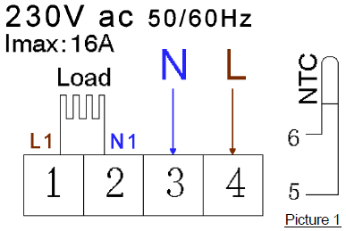
- Wire the thermostat as per picture 1 making sure all the terminals are done up tightly. An under floor sensor must be used (supplied) and this MUST only be wired to terminals 5 and 6. Polarity of the sensor does not matter. Do NOT exceed total load of 16A. For loads greater than this, use a contactor with the thermostat controlling the coil of the contactor.
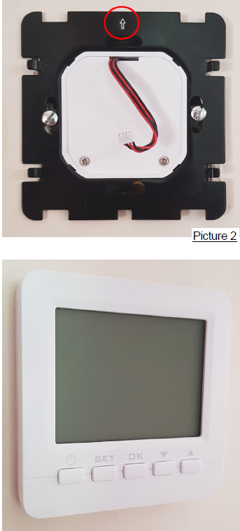
- Once all the connections have been made, make sure the arrow on the back plate faces upwards and secure to the back box using two screws. See picture 2 to the right.
- Slide on the centre housing until it clips into position. See picture 3 above.
- Finally push the plug into the socket on the front screen and clip onto the centre housing.
- Note:– The plug only fits one way around so don’t force it.
CHANGING THE MASTER / DEFAULT SETTINGS
There are various master / default settings that can be changed by entering the default settings. To enter these settings, turn off the thermostat by pressing the![]() button. Then press and hold the
button. Then press and hold the![]() button for 3-5 seconds until the A1 appears on the screen. You are now in settings mode and if you don’t press any button for 5 seconds the display reverts back to off mode. Press
button for 3-5 seconds until the A1 appears on the screen. You are now in settings mode and if you don’t press any button for 5 seconds the display reverts back to off mode. Press![]() button to switch to next option and press
button to switch to next option and press ![]() or
or ![]() buttons to adjust the data. If you wish to exit the settings without waiting 5 seconds press the
buttons to adjust the data. If you wish to exit the settings without waiting 5 seconds press the![]() button.
button.
| No. | Setting Options | Data Setting Function | Default |
|
A1 |
Temperature calibration |
-9⁰C to +9⁰C in 0.5⁰C steps. (Can be used to tune temperature reading so it matches another
thermostat) |
0⁰C |
| A2 | Differential between set point and On and Off | 0.5⁰C – 2.5⁰C in 0.5⁰C steps. | 0.5⁰C |
| A3 | Floor sensor differential | 1⁰C – 9⁰C in 1⁰C steps. | 2⁰C |
|
A4 |
Sensors used |
N1= Built in sensor only. N2= Floor sensor only N3= Built in sensor and floor sensor.
If floor sensor temperature is higher than its set point (A6) load will turn off (indicated by |
N3 |
| A5 | lock settings | 0 = half lock 1 = full lock | 0 |
| A6 | Maximum set point of floor sensor. | 5⁰C – 45⁰C | 27⁰C |
| A7 | Minimum set point of floor sensor. | 1⁰C – 10⁰C or ( = Not active) | 5⁰C |
| A8 | Minimum set point of internal sensor. | 1⁰C – 10⁰C | 5⁰C |
| A9 | Maximum set point of internal sensor. | 20⁰C – 45⁰C | 30⁰C |
|
AA |
Power Cut function. |
0 = Power heating as per controller memory. 1 = Shut down controller after power cut.
2 = Shutdown heating but turn controller on after power cut. |
0 |
|
AB |
Programming selection |
0 = 5 + 2 (same settings Mon-Fri + Sat-Sun) 1 = 6 + 1 (same settings Mon-Sat + Sun)
2 = 7 (different settings each day Mon-Sun) |
0 |
|
AC |
Window Opening detection |
= Not active
10 – 20⁰C = Sudden drop set point at which heating turns off. |
|
| AD | Window Opening OFF period | 5 – 40 minutes (only if AC above is set to a temperature and not ). | 10 |
| AE | Factory Reset | Press & hold ok key until whole screen shows. |
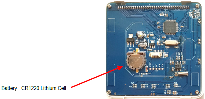
BATTERY REPLACEMENT
The thermostat contains an internal battery that maintains the settings should you have a power failure. If you find the settings are not remembered after a power cut, the battery needs replacing.
- Before replacing the battery, ensure the mains power is completely turned off and isolated.
- Remove the front screen panel as per instruction.
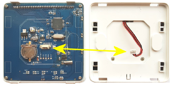
- Disconnect the plug connecting the front screen to the back of the controller.
- Replace the battery with another ensuring polarity is correct.
- Dispose of the old battery correctly.
- Reassemble is reversal of above.
SENSOR FAULT CODES
- E1 or E2 fault codes are displayed if the sensors are faulty or are not connected. The thermostat will stop heating until the fault is corrected.
- If in the master settings shown overleaf, you have selected N3 for option A4 (Sensors used) you MUST have a floor sensor present and working otherwise the display will show fault code E2 and will not work.
NOTE: It is our policy to continually improve products and as such we reserve the right to alter data, specifications and component parts without prior notice.
![]() This product conforms to EU Directive 2002/96/EC. This appliance bears the symbol of the crossed waste bin. This indicates that, at the end of its useful life, it must not be disposed of as domestic waste, but must be taken to a collection centre for waste electrical and electronic equipment. It is the user’s responsibility to dispose of this appliance through the appropriate channels. Failure to do so may incur penalties established by laws governing waste disposal.
This product conforms to EU Directive 2002/96/EC. This appliance bears the symbol of the crossed waste bin. This indicates that, at the end of its useful life, it must not be disposed of as domestic waste, but must be taken to a collection centre for waste electrical and electronic equipment. It is the user’s responsibility to dispose of this appliance through the appropriate channels. Failure to do so may incur penalties established by laws governing waste disposal.
REGISTER: Activate your warranty by registering online at www.bnthermic.co.uk and retain this installation data for future reference.
IMPORTANT: No liability is accepted for incorrect use of this product.
WARRANTY
Your BN Thermic product is guaranteed for one year from date of purchase. We will repair or replace at our discretion any part found to be defective. We cannot assume any consequential liability. This guarantee in no way prejudices your rights under common law and is offered as an addition to consumer liability rights.
Contacts
BN Thermic Ltd
- 34 Stephenson Way, Crawley, RH10 1TN
- Tel: +44 (0) 1293 547361
- Email: [email protected]
- Web: www.bnthermic.co.uk
B16CINS-v01
Reference
Download Manual:
bnthermic B16C PROGRAMMABLE ROOM THERMOSTAT INSTRUCTIONS Manual
bnthermic B16C PROGRAMMABLE ROOM THERMOSTAT INSTRUCTIONS Manual
Leave a Reply