
Becasmart BHT-2002 Heating Programmable Thermostat
Thank you for purchasing our products, please read the following terms before installation and use: Please confirm that this product is suitable for your heating equipment before installation;
- Before installation or maintenance, please make sure to keep the power off;
- Please strictly follow the wiring diagram for wiring installation;
- Installation to the wall, please confirm that the fasteners are suitable for this product;
- Do not pull the cable too hard, otherwise, the product will be damaged;
- If a hard plastic wire is used in the installation process, it must be bent to an appropriate angle in advance;
- Please arrange for professionals to install it;
- Please contact the after-sales service for equipment failure, please do not try to repair it yourself;
- After installation, please refer to this manual to check again to ensure normal and safe use, and keep this manual properly.
ABOUT YOUR THERMOSTATS
The BHT-2002 range has been developed to control electric underfloor, water heating, or water/gas boiler system. These units are designed for use in commercial, industrial, civil, and domestic properties.
In the box, you will find
- Thermostat 1pc Screws 2pc
- User Guide 1pc
- QC Passed 1pc Floor Sensor
- 1pc(Floor Sensor is Optional)
TECHNICAL DATA
- Power Supply:95 ~240 VAC, 50~60Hz
- Current Load: 5A (Water heating, water/Gas boiler),
- 16A (Electric heating)
- Sensor: NTC3950, 10K
- Accuracy: ±0.5°C
- Set Temp. Range: 5-35°C
- Room Temp. Range: 5-99°C
- Display Temp. Range: 5 ~ 99°C
- Ambient Temp.: 0~ 45°C
- Ambient Humidity: 5 ~ 95 % RH (Non-Condensing)
- Storage Temp.:-5~ 45°C
- Power Consumption: <1. 5W
- Timing Error: < 1%
- Shell Material: PC +ABS ( Fireproof)
- Installation Box: 86 * 86mm Square or European 60mm Round Box
- Wire Terminals: Wire 2 x 1.5 mm2 or 1 x 2.5 mm2
- Protection Class: IP20
- Buttons: Capacitive Touch Buttons
MODEL DEFINITION
- GA: Water heating, 5A
- GB: Electric floor Heating,16A
- GC: Water/Gas Boiler, 3A
- L: Backlight
- W: Wifi
- For example BHT-2002 GCLW
FEATURES
- Excellent UI design, both beautiful and practical.
- H9 tempered glass screen, scratch-resistant and easy to clean;
- Compatible with standard 86mm square cassettes and 60mm European cassettes to meet all installation environments;
- Strict temperature control accuracy (± 0.5°C) to provide the warmth you want;
- Power off protection, save all your settings safely;
- Provide weather information and humidity display
- Preset adjustment of 5+1+1 mode in a week, programmable setting of 6 time periods a day, green energy saving,
- Less cost, more intelligence, and environmental protection;
- Support the creation of product local groups/shares to achieve unlimited centralized control of the number of products/ multi-terminal control;
- Perfect access: Tmall Genie, Amazon Echo, Google Home, full experience new voice control methods;
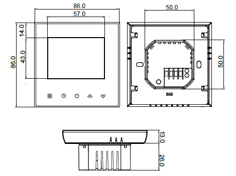
DIMENSION:(mm)
BEFORE WIRING AND INSTALLING
- Read these instructions carefully. Failure to follow them could damage the product or cause a hazardous condition.
- Check the ratings given in the instructions and on the product to make sure the product is suitable for your application.
- Installer must be a trained, experienced service technician.
- After installation is complete, check out product operation as provided in these instructions.
WIRING
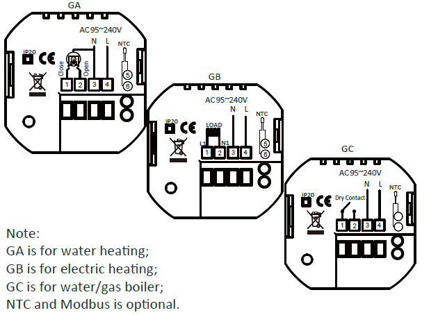
Note:
GA is for water heating;
GB is for electric heating;
GC is for water/gas boiler;
NTC and Modbus are optional
CAUTION Electrical Shock or Equipment Damage Hazard. Can shock individuals or short equipment circuitry. Disconnect the power supply before installation.
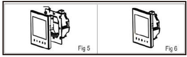
INSTALLATION
Your thermostat is suitable for installation within a standard 86mm
press box or European 60mm press box.
Step 1. Keep power off. See Fig 1.
Step 2. Remove the mounting plate by pushing the panel assembly. See Fig 2.
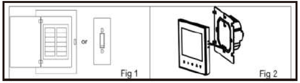
Step 3. Connect the power supply, and load it into the appropriate terminals. (see “Wiring your thermostat” for details and Fig 3).
Step 4. Fix the mounô plate into the wall with screws in the box. See Fig 4.
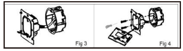
Step 5. Fix the thermostat body and the plate by the lower bu􀀂on. See Fig 5.
Step 6. Installaôon complete. See Fig 6.
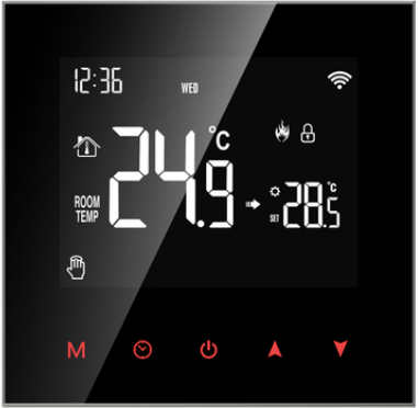
HOME SCREEN QUICK REFERENCE
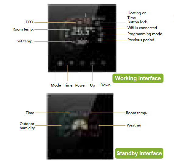
Note: The weather and humidity will be synchronized within 1 hour after the device is connected to the Internet for the first time, and the weather will be synchronized every hour thereafter.
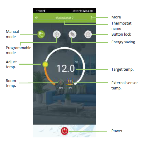
Press the ![]() in the power-on state to display the humidity and set the temperature
in the power-on state to display the humidity and set the temperature
OPERATION
During Power On
- Power On/off: Press power off to turn the thermostat on/off.
- Funcom & Programmable
Touch to change between manual mode
 and program mode.
In manual mode, will show on the display,
In programmable mode , and will
  show on the display.
 - Setting Temperature
In the programming mode, the temperature setting and time setting will be locked. If the user wants to adjust, he must first adjust the thermostat to manual mode by pressingthe key. In the mode of manual, press to set the desired temperature.
 - Adjusting/Setting the Clock
Pressto set minute, hour, and weekday. By using the
Pressonce more to confirm and exit. - Locking your Thermostat
Pressand hold the for 8 seconds to lock /unlock your thermostat In item 3 of high senior options, you can select full lock or half lock .
. - Adjusting/Setting the Programmable Schedules
Press theicon four times in a row. You can see “1-5” and”06:00“, and the minutes of time is flashing.
Use to set the minutes;
Press the icon again, and the hour of the time will flash, set the hour by .
Press the icon again, the temperature setting will flash, set the temperature by ;
This completes the setting of periods1 .”
In the same way, complete the settings of periods 2, 3, 4,5and 6.
Press the icon once more to enter the Saturday schedule settings (you will see the SAT on the screen). Repeat the above process to set the period and temp. and Sunday schedule.
Press the icon once more to confirm and exit.
Default settings for program schedule
|
Time display |
MON.-FRI.
(①②③④⑤ shows on screen) |
SAT.
(⑥shows on screen) |
SUN.
(⑦shows on screen) |
|||
| TIME | TEMP. | ON-TIME | TEMP. | ON-TIME | TEMP. | |
| Period 1 | 6:00~8:00 | 20 | 6:00~8:00 | 20 | 6:00~8:00 | 20 |
| Period 2 | 8:00~11:30 | 15 | 8:00~11:30 | 20 | 8:00~11:30 | 20 |
| Period 3 | 11:30~13:00 | 15 | 11:30~13:00 | 20 | 11:30~13:00 | 20 |
| Period 4 | 13:30~17:00 | 15 | 13:30~17:00 | 20 | 13:30~17:00 | 20 |
| Period 5 | 17:00~22:00 | 22 | 17:00~22:00 | 20 | 17:00~22:00 | 20 |
| Period 6 | 22:00~6:00 | 15 | 22:00~6:00 | 15 | 22:00~6:00 | 15 |
A separate schedule may be set for weekdays (Mon – Fri) and for weekends (Sat or Sun).
Checking the Temperature of the Floor Sensor
Press and hold the ![]() arrow for 8 seconds to display the temp. of floor sensor. If there is no external sensor, “err” will be displayed
arrow for 8 seconds to display the temp. of floor sensor. If there is no external sensor, “err” will be displayed
Setting the Functions and Options
During Power Off, press and hold for 8 sec. in the order to reach the system function. Then press to scroll through the available functions, and use the arrows to change the available options. All settings are confirmed automatically.
| Code | Function | Setting and options | Default |
| 1 | Temperature compensation | -9 to 9 ℃ | -3 |
| 2 | Deadzone Temp. | 1-5℃ | 01 |
|
3 |
Button Locking |
01:All buttons are locked except the power button. 01:All buttons are locked. |
01 |
|
4 |
Sensor typer |
In: Internal Sensor(to control the temp.) Ex: External Sensor(to control the temp.) Ou: Only external sensor
AL: Internal/External Sensor (Internal sensor to control the temp., external sensor to limit the temp.) |
AL |
| 5 | Min.Set Temp. | 5-15℃ | 5 |
| 6 | Max.Set Temp. | 15-45℃ | 35 |
| 7 | High temperature
protection setting. |
25-70℃ | 45 |
| 8 | Low temperature protection setting. | 0-10℃ | 0 |
| 9 | Energy saving Mode | 00:Non-energy saving Mode 01:Energy saving
Mode |
00 |
| 10 | Energy saving
Temp. |
0-30℃ | 20 |
| 11 | Standby Brightness | 3-99 | 5 |
| 12 | Version number | U1 |
ABOUT WIFI
WI-FI CONNECTION
Before using your Wi-Fi thermostat for the Wi-Fi signal and through your smartphone or tablet, This will all communication between your connected devices
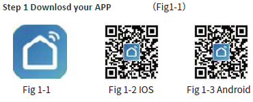
Search for “Smartlife” in Apple Store or Google Play or use a browser to scan the QR code above (Figure 1-2), and complete account registraôon and installation according to the guidance of the APP.
Step 2. Connect the thermostat
Check the tutorial below to complete the on and setup
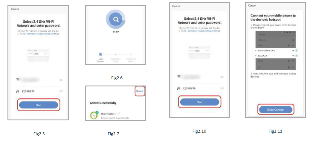
Method 1: Scan the QR code to the network guide (Fig 2.1-Fig 2.3)
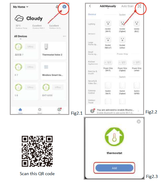
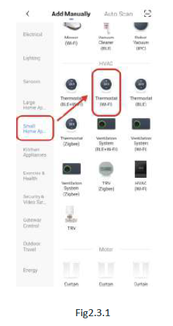
Method 2: Ordinary distribution network guidance (Fig. 2. 1&Fig. 2.3.1)
Network distribution mode:
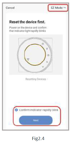
EZ Mode
When the thermostat is off, press and hold the thermostat screen flashes quickly and displays the
  icon, and then operate according to the following figure (Fig 2.4-Fig 2.7).
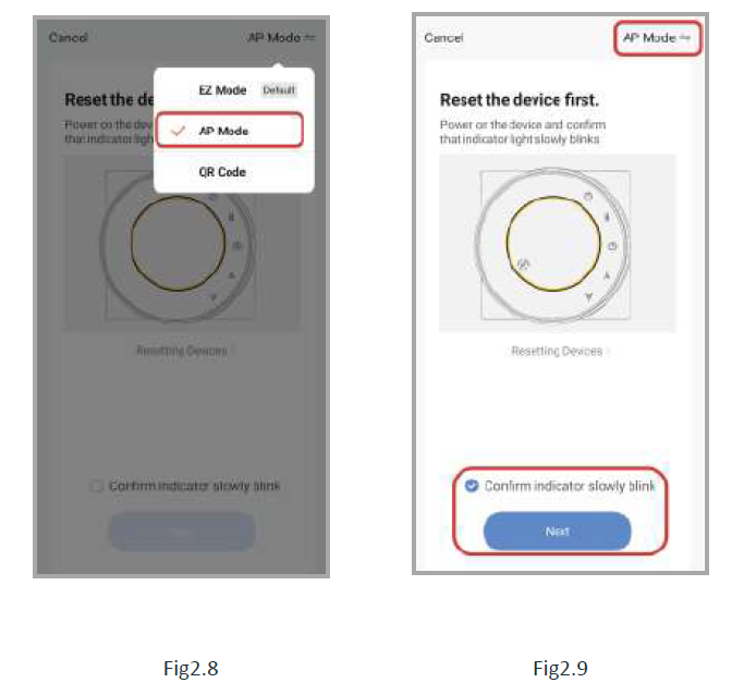
AP Mode
When the thermostat is off, press and hold the ” ” the thermostat screen flashes slowly and the “ ” icon is displayed (if the ”
 ![]() ” icon appears, continue to press the ” ” the thermostat screen Flashes slowly and displays the “
” icon appears, continue to press the ” ” the thermostat screen Flashes slowly and displays the “ ![]() ” icon), and then operate according to the following figure (Fig 2.8-Fig 2.14).
” icon), and then operate according to the following figure (Fig 2.8-Fig 2.14).
APP operation interface description (heating thermostat
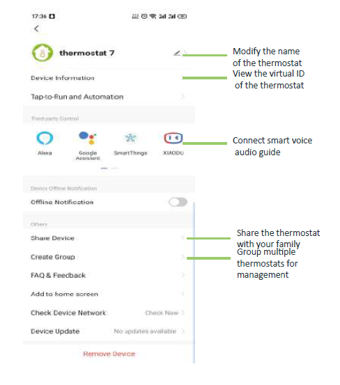
More settings
SIMPLE EXCEPTION HANDLING
| No. | Phenomenons | Handling |
| 1 | The power is on but without display. | *Check if the terminals between the LCD panel and Power Unit Box are loosen. |
| 2 | Without output but display works. | * Use a new LC panel or new Power Unit Box to replace the old one. |
| 3 | Room Temp. Is a ltile different from the actual. | * Do temperature calibration in item 1 of high senior options |
SERVICE
Your thermostat carries a 24 months warranty from the date of purchase. Service outwith the warranty period may incur a charge. For more detail please contact us directly.
Reference
Download Manual
Becasmart BHT-2002 Heating Programmable Thermostat User Manual
![]()
Becasmart BHT-2002 Heating Programmable Thermostat User Manual
Leave a Reply